Energy Conservation in Tree-based Event Driven
Wireless Ad-hoc Networks
Itu Snigdh
Department of Comp.Sc& Engg Birla Institute of Technology, Mesra, Ranchi, Jharkhand, India
Rumanshu
Department of Comp.Sc& Engg Birla Institute of Technology, Mesra, Ranchi, Jharkhand, India
ABSTRACT
Wireless nodes communicate over wireless links that typically have less bandwidth than in a wired network. Each node in a wireless ad hoc network functions as both a host and a router, and the control of the network is distributed among the nodes. The network topology is in general, dynamic, as the connectivity among the nodes may vary with time because of node departures, new node arrivals, and the change of environments. Hence, there is a need for efficient routing protocols to allow the nodes to communicate over multihop paths. This paper focuses on the effect of topology that requires to be locally and self-adaptively maintained, at a low communication cost, without affecting QOS. The preliminary research shows the contrast of energy expedited in a tree based network over the usual graph based network employing directed diffusion. The method achieves lesser energy consumption owing to reduction of the no of bits though unicast communication and discarding other redundant messages arriving later, thereby constricting the network to have at most one transmission for one event.
General Terms
Wireless Network, Event- driven, Energy, Tree construction.
Keywords
Adhoc network, energy conservation, routing, tree based backbone structure.
1.
INTRODUCTION
Wireless network refers to a network that does not depend upon and does not require any kind of wires or cables for the establishment of the connection for communication among the various devices. These devices may be computers, mobiles or sensors etc. These networks use radio waves and/or microwaves to maintain connection among the communicating devices. They can be categorized into two different categories on the basis of their network architecture (i) Infrastructure based networks, and (ii) Infrastructure less (adhoc) networks [1].
An Adhoc network is a decentralized type of the wireless network [2]. The network gets its name as it does not depend on any pre-existing architecture. Every time a new network is constructed, that is different from the previously constructed one. All nodes or devices are connected dynamically, since they possess the property of mobility. The mode of
connectivity also depends according to the application requirement. Moreover each one of them can behave like a router as no default router is designated for use. It is a type of a network where every device has equal status and is free to connect to any other devices within its sensing range. Some of the fundamental properties of adhoc networks [2] are
i. Dynamic topologies, ii. Limited channel bandwidth, iii. Variable capacity links,
iv. Energy constrained operations, and v. Limited physical security.
The inevitable question is: Why are adhoc networks considered hard to establish? Primarily because (a) Routing is major issue as the topology is continuously changing, (b) Security is major issue as any device can add or leave the network at any point of time, adding to new vulnerabilities due to nasty neighbors, and (c) Power as all the devices are being running on the battery power which is limited thus the computation power availability is little for the devices [3]. Adhoc Network typically consists of limiting device energy and hence conservation deserves attention. These kinds of networks consist of a number of small, low power, and low communication range sensing nodes which cooperatively monitor the environment and transmit data through a route (the collection of links edges in the network topology graph) between nodes from data sensor node to the Base Station (BS) or to the sink. This task is critically energy consuming that cause the network out of service, very soon, due to the limited power of the nodes. Therefore energy efficient data dissemination routing-protocols are attended. Since, the network lifetime does not depend on single node failure unless it does not have any impact on the communication among the other nodes and the sink node. Or we can say network lifetime can be defined as the useful time where messages are exchanged toward to sink with minimum required active nodes.
Routing can be defined as a mechanism or the process of establishing or selecting the path between the two devices for the purpose of forwarding the data packets from the source to the destination [4]. The path can be selected on the basis of no. of hops, delay etc. Routing directs packet forwarding, the transit of logically addressed packets from their source toward their ultimate destination through intermediate nodes, typically, hardware devices called routers, bridges, gateways or switches. A router has basically two functions: forwarding (incoming packets) and updating routing tables. These protocols can be classified as [5, 6, and 7]
(i) Proactive routing protocols/ Non-adaptive algorithm (table-driven routing).
(ii) Reactive routing protocols/ Adaptive algorithm (on-demand routing) and
(iii) Hybrid routing protocols.
2. RELATED WORK
2.1 Strategies
subject to the performance metrics energy conservation and lifetime enhancement. Unlike traditional wired and cellular networks, the movement of wireless devices during communication could change the network topology to some extent. Hence, it is more challenging to design a topology-control algorithm for an ad hoc wireless network. The backbone structure of the wireless network can be broadly classified as (i) graph-based, and (ii) tree-based.
In a graph-based structure, the nodes form a graph for the establishment of the network. Thus, in this case, there can exist multiple paths between any pair of source and destination nodes. The route for forwarding the data from the source node to the destination node is either decided on the basis of the previously constructed table as in case of the Proactive routing and dynamically as in case of the Reactive routing protocol.
In tree-based structure the nodes used to form a tree instead of a graph for the establishment of the network. In this case there exist only path between the parent and the child node thus; it helps a lot in minimizing the redundancies. The child node or the internal node gather the data and forward it to its parent node. The parent node aggregates the data and further forwards it to its parent and this process goes on till the data reaches the root node. Tree based structure can be further categorized into two different categories (a) routing based, and (b) architecture based.
In routing based tree structure we use to generate tree at the time of routing. When a data packet is needed to be forwarded we decide or establish the path after generating a tree structure within the graph which is being rooted at the destination node. After which simple forwarding of data is being done from source to the destination node. Such type of structure can also be categorized as (i) Minimum Spanning Tree based, and (ii) Cluster based.
In case of architecture based tree structure, the backbone structure of the network consists of tree architecture instead of graph, formed at the time of establishment of the network. EDGE [8] is based on a tree topology rooted at a sink node. Every sensor must be a member of the tree, i.e., an internal or leaf node, in order to communicate with the sink. The design of EDGE has been driven by the goals: Simplicity, Scalability, and Robustness.
2.2 Foundation Survey
The literatures till date mention the advantages of different protocols in context of different architectures. The tree based backbone structure is better than the graph based backbone structure. As in graph based structure the route is to be defined or establish whenever we need to forward the data from a source node to the destination node while in case of tree based structure once the tree is being constructed there is no further need for route establishment every time when a data is needed to be forward to a destination node from any other node. In tree structure the nodes simply forward the data packet to their parent node till the data packet reaches out the sink or the root node. Thus it can also be stated that instead of using broadcast scheme for delivering the data as in case of graph based structure, unicast scheme is used for tree based structure. Hence reducing the total no. of data packets to be forwarded which is result in reducing the energy consumption of the network. This paper aims to investigate the total energy consumed by a network in a tree based architecture that models the merits of edge as a communicating architecture. Section 2 discusses the different phases of backbone formation of the network on the basis of a hybrid strategy EDGE [8]. Section 3 illustrates the system model. Within which Section 3.1 provides the list of assumption, and Section
3.2 explains the algorithm. Results and simulation are discussed in section 4.
2.3 Backbone Formulation
Constructing the Tree
Base station initiates the tree construction by broadcasting the child request (CRQ) packet. A Nonmember node (i.e., not the part of the tree) decide to join as child node on the bases of received CRQ packets who so ever has shortest waiting time. Every node maintains a parental candidate (PC) table, for the alternate parent list, which has the two fields i.e., candidate IDs and metrics. A Member node (i.e., those nodes which are the part of the tree) updates there PC table on getting the CRQ packets. After choosing a parent the Nonmember node sends back child reply (CRP) packet to that node. After which the parent node send back the acceptance to the Nonmember node in form of child acceptance (CAC) packet to it. On receiving the CAC packet the child node performs the same procedure as its parent.
Adding the new nodes
When a new node comes into the scenario it wants to join the tree. For that it broadcast a parent request (PRQ) packet, so that the neighboring nodes get aware of its existence. After hearing the request the Member nodes send back the CRQ packet to it. Then, same tree construction procedure is followed.
Dealing with node failures
There are three different scenarios for leaving procedure.
a. In first case the orphaned node checks it PC table for its most appropriate alternate parent and then send the CRP packet to it and waits for getting back the CAC packet.
b. In second case if there is no alternate parent available in the PC table, it uses the joining procedure as the newly deployed node except for the difference that the broadcasted PRQ packet is not been received by the child or grandchild nodes of the orphaned node.
c. In third, worst case when the above two condition does not hold, it sends the parent query (PQR) packet to its child so they may have any candidate for becoming the parent node of orphaned node. The child nodes reply with the parent reply (PRP) packet, having all the required information, to the orphaned node. Then the orphaned node randomly selects any 1 among them and send reverse (REV) packet to that node, informing the reversal of the relation.
2.4 Comparison
2.4.1
Comparison of EDGE with graph-based
structure
leaving scenarios, considering the load in bytes per sec, for 512 and 1024 bytes. [8]
2.4.2
Comparison of EDGE with tree-based
structure
[image:3.595.11.315.459.772.2]Adaptive Spanning Tree Routing is based on Minimum Spanning tree with a slight modification or enhancement according to the dynamically changing network [13]. Clustering tree based protocol [14] considers the nodes capability and network environment as the major issues for the protocol design. The ratio of the Cluster Head (CH) is set according to the scale and density of the network and the clustering mechanism is implemented based on some factors such as node’s energy and the distance between nodes. Reference Broadcast Synchronization (RBS) and Timing-sync Protocol for Sensor Network (TPSN) are also tree based protocols. TPSN consumes less energy over RBS, at the cost of reduced reliability [15]. Tree Based Routing Protocol (TBRP) [16] achieves a good performance in terms of lifetime by balancing the energy node among all the nodes. It introduces a new clustering factor for cluster head election. It also introduces a simple but efficient approach, namely, fuzzy spanning tree for sending aggregated data to the base station. Hierarchical Addressing Tree (HAT) [17] routing protocol works in two phases (i) Association and (ii) Routing. In Association phase it constructs the tree in four steps: (a) Initialization state, (b) Scanning state, (c) Collects Beacons (BCN), and (d) Join network using three-way handshake. Routing phase is responsible for end-to-end delivery. It uses four different strategies for that: (a) Local Broadcast (one-hop neighbors), (b) Broadcast (multi-hop), (c) Unicast (check child-entry in Routing table), and (d) To_PAN_Coord (destined to the root of the tree).
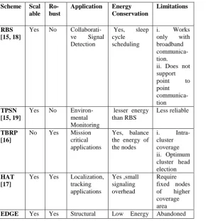
Table 1. Performance comparison among tree based routing strategies
Scheme Scal able
Ro-bust
Application Energy Conservation
Limitations
RBS [15, 18]
Yes No Collaborati-ve Signal Detection
Yes, sleep cycle scheduling
i. Works only with broadband communica-tion. ii. Does not support point to point communica-tion
TPSN [15, 19]
Yes No Environ-mental Monitoring
lesser energy than RBS
Less reliable
TBRP [16]
No Yes Mission critical applications
Yes, balance the energy of the nodes
i. Intra-cluster coverage ii. Optimum cluster head election
HAT [17]
Yes Yes Localization, tracking applications Yes ,small signaling overhead Require fixed nodes of higher coverage area
EDGE Yes Yes Structural Low Energy Abandoned
[8] Health
Monitoring
consumption nodes rejoin the tree.
3. SYSTEM MODEL
Considering a small scale event driven WSN for monitoring structural systems, a random deployment of 50 sensors is done. These sensors are static, homogeneous in nature and have only 2 hop communication. Using the backbone structuring procedure an initial tree is established. On occurrence of events the structure responds by sending a unicast message to their respective parents. The parent transmits immediately after reception of the message and discards other redundant messages arriving later, hence constricting the network to have at most one transmission for one event.
3.1
List of Assumptions
There are certain assumptions that have to be made before constructing the tree based on EDGE.
(i) The no. of sensor nodes are less in number and not more than 50, as building the application for small structural health monitoring such as electronic devices monitoring the sudden environmental or other changes having harmful effect.
(ii) There is a threshold value of having a maximum no. of child nodes that a parent node can hold approximately about 5-6. After reaching the threshold value the node will not entertain any further child request.
(iii) Nodes are being randomly deployed within the certain area of the device which has to be monitored.
(iv) It may be possible that the nodes remain in dormant status if
(a) They are not within the range of any other nodes i.e., they don’t have any node within its range to communicate with.
(b) Or the approachable parent node has already been reached the threshold factor of having maximum child nodes.
(v) One node will behave as / become the base station who initiates the construction.
3.2
Algorithm
i. Base station initiates the EDGE construction.
ii. Set Sensor Range, Threshold value for no. of child of every node = T
iii. Create/ Deploy Sensors
NOS = No. of Sensors
iv. Broadcast()
{ { for(int i=1 to NOS)
{ if(Sensor distance <= Sensor Range)
{ Assign child IDs to the parent node (base station)
Assign parent ID to all the child nodes
} }
ChildBroadcast(0);
v. ChildBroadcast(int index)
{ if (Sensor[index] has at least 1 child)
{ for (int i=0 to no. of child of Sensor[index])
{ get the child index of the Sensor[index]
for (int j=1to NOS)
{ if (Sensor distance <= Sensor Range)
{ create the table for the node Sensor[index]
{
Assign child IDs to the parent node (j)
Assign parent ID to all the child nodes
} } } }
for(int i=0 to no. of child of Sensor[index])
{
ChildBroadcast(Sensor[index].GetchildID(i));
} } }
vi. AddNode()
{ Sensor[NOS+1] //newly deployed Sensor
if(Sensor[NOS] has no parent)
{
for(int i=1 to NOS+1)
{ if(Sensor distance <= Sensor Range && has no parent)
{ create the table for newly deployed sensor
if(no of child of new Sensor < T && has no parent)
{
Assign child IDs to the parent node (new node)
Assign parent ID to all the child nodes
} } }
for(int i=0 to no. of child of Sensor[index])
{ ChildBroadcast(SensorA[NOS].GetchildID(i));
}
NOS++;
} }
3.3
Snapshots of Randomly Constructed
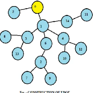
[image:4.595.48.526.55.700.2]Tree
[image:4.595.353.505.116.268.2]Figure 1: Construction of the tree.
Figure 2:Adding of a new node.
Figure 3:Dealing with node failure.
4. SIMULATION AND DISCUSSION
[image:4.595.354.503.503.667.2]Moreover since our method unlike DD uses unicast communication and ignores the redundant messages at the parent level, the number of bits required in communication is substantially less and so is the transfer energy. The Algorithm has been simulated in JAVA for different tree structure for a set of 5 events each.
4.1
Transmission Energy
The energy consumed by transmitting amplifier for short range communication is ∝d2 and the energy consumed in long range transmission is ∝ d4.
ETij = l Ee + l εl *(dij)
4 .……
4.1
and
ETij = l Ee + l εs *(dij)
2 …….
4.2
where,
l = no. of msg. bits (1 bit for tree construction and 9 bits for Directed Diffusion).
4.2
Transfer Energy (E)
E= ∑N
j=1EjP + K*ER ……...4.3
Where,
EjP= Transmission Energy of Each node to the base node traversing the Routes of the EDGE protocol.
ER = Received energy ER = lEe + lEBF
[image:5.595.315.542.71.276.2]K= No of Member Nodes.
Table 4.Showing values of the constant of radio model.
Constant Description Value
εl energy consumed by the
amplifier to transmit at a longer distance
0.0013 pJ/bit/m4
εs energy consumed by the
amplifier to transmit at a shorter distance
10 pJ/bit/m2
Ee energy consumed in the electronics circuit to transmit or receive the signal
50 nJ/bit
EBF energy consumed for
beam formings
[image:5.595.315.540.317.520.2]5 nJ/bit
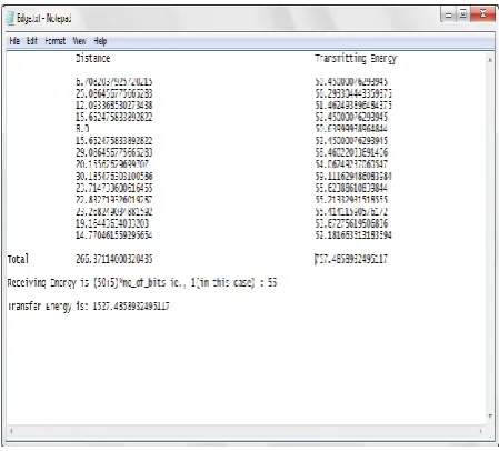
[image:5.595.48.287.409.565.2]Figure 4:File showing the distance and energy values of directed diffusion protocol.
Figure 5:File showing the distance and energy values of EDGE protocol.
The figure 6 shows comparison for the distance factor of each node with the base station in both the Directed Diffusion as well as in tree based backbone architecture.
[image:5.595.321.539.604.715.2]The figure 7 shows comparison for the transmission energy on the bases of the distance calculated between the nodes and base station using the formula 4.1 in case of the Directed Diffusion and formula 4.2 in case of tree based backbone architecture.
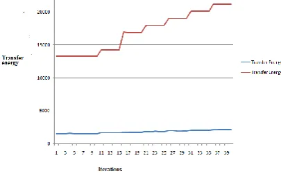
Figure 7:Transmission energy graph.
The figure 8 shows comparison for the total energy considered as the summation of the transmission energy and receiving energy using the formula 4.3 in case of the Directed Diffusion and formula 4.3 in case of tree based backbone architecture.
Figure 8: Total transfer energy graph.
5. CONCLUSION
In tree structure the nodes simply forward the data packet to their parent node till the data packet reaches out the sink or the root node. Thus it can also be stated that instead of using broadcast scheme for delivering the data as in case of graph based structure, unicast scheme is used for tree based structure. Hence reducing the total no. of data packets to be forwarded which result in reducing the energy consumption of the network. This scheme can cater to node failures by redeployment of nodes that can join the existent network. This work is a preliminary assessment of the benefits of using a tree structure for coverage on the basis of energy expedited and can be further extended for lifetime maximisation against node failures. Since this deployment has been studied for small scale networks with fewer nodes, scalability becomes the limiting issue.
6. REFERENCES
[1] Lin, Fu, Zhang, Deng-Yi; Li, Wenhai,“ Research on Quality of Service in Wireless Sensor Networks”, IEEE 2nd International Conference, 15- 17 July 2011
[2] C K Toh, “Ad Hoc Mobile Wireless Networks”, Prentice Hall Publishers, 2002.
[3] P. Gupta and P.R. Kumar, “Capacity of wireless networks”. IEEE Transactions on Information Theory, Volume 46, Issue 2, March 2000.
[4] Andrew S. Tanenbaum, “Computer Networks”, third edition, Network series, Pearson Education India, 2008. [5] Tony Lasson & Nicklas Hedman (1998) “Routing
protocols in wireless Ad hoc network” Lulea University of technology, Stockholm.
[6] Lee Kok Thong (2004) “Performance analysis of mobile adhoc routing protocols” thesis Naval post graduate college, Monterey, California.
[7] M. Abolhasan, T. Wysocki, and E. Dutkiewicz, “A review of routing protocols for mobile ad hoc networks”, Ad Hoc Networks, vol. 2, no. 1, pp. 1.22, Jan. 2004.
[8] Niwat Thepvilojanapong, Yoshito Tobe, Kaoru Sezaki,“On the Construction of Efficient Data Gathering Tree in Wireless Sensor Networks”, Circuits and Systems, 2005. ISCAS 2005. IEEE International Symposium, 23-26 May 2005.
[9] Perkins, Charles E. and Bhagwat, Pravin (1994) “Highly Dynamic Destination-Sequenced Distance-Vector Routing (DSDV) for Mobile Computers”. Retrieved 2006-10-20.
[10] T. Clausen and P. Jacquet, “Optimized link state routing protocol (OLSR)”, IETF, RFC 3626, Oct. 2003. [11] D. B. Johnson, D. A. Maltz, and J. Broch, “DSR: The
dynamic source routing protocol for multi-hop wireless ad hoc networks”, in Ad Hoc Networking, C. E. Perkins, Ed. Addison-Wesley, 2001, pp. 139.172.
[12] Perkins, C.; Belding-Royer, E.; Das, S. (July 2003), “Ad hoc On-Demand Distance Vector (AODV) Routing”, IETF. RFC 3561. Retrieved 2010-06-18.
[13] Ying Zhang and Qingfeng Huang, “Adaptive Tree: A Learning-based Meta-Routing Strategy for Sensor Networks”, Consumer Communications and Networking Conference, 2006, 3rd IEEE.
[14] Wang, Yongheng; Zhang, Xiaoming, “Internet of Things”, Chapter - Optimized Clustering Tree Based Routing Protocol for Wireless Sensor Networks, Communications in Computer and Information Science Volume 312, 2012, pp 192-199.
[15] François Delobel, Alexandre Guitton, Michel Misson, Waltenegus Dargie: “Minimization of the Diffusion Delay of a Tree-Based Wireless Sensor Network”. GLOBECOM 2011: 1-6.
[16] Mohammad Zeynali, Leili Mohammad Khanli, and Amir Mollanejad, “TBRP: Novel Tree Based Routing Protocol in Wireless Sensor Network”, International Journal of Grid and Distributed Computing, Vol. 2, No. 4, December, 2009.
[17] Luca Borsani, Sergio Guglielmi, Alessandro Redondi, Matteo Cesana, “Tree-Based Routing Protocol for Wireless Sensor Networks”, Wireless On-Demand Network Systems and Services (WONS), 2011 Eighth International Conference, 26-28 Jan. 2011.
[18] Jeremy Elson, Lewis Girod and Deborah Estrin, “Fine-Grained Network Time Synchronization using Reference Broadcasts”, UCLA.
[19] Saurabh Ganeriwal, Ram Kumar, Mani B. Srivastava, “Timing-sync protocol for sensor networks”, SenSys 2003: 138-149
[image:6.595.61.264.335.462.2]