A Comparison between a Fuzzy and PID Controller
for Universal Motor
Abdelfettah Zeghoudi
URMER Research unit, Tlemcen University, B.P. 119, Tlemcen, Algeria
Ali Chermitti
URMER Research unit, Tlemcen University, B.P. 119, Tlemcen, Algeria
ABSTRACT
This paper describes the use of PID controller, and fuzzy logic controller techniques to control of a motor. Using Matlab/Simulink, This work seeks to identify the strengths and weaknesses of each of the two pilots, for the fuzzy logic controller (Intelligent Control). The system performance is evaluated in comparison with a traditional PID control scheme. Both simulation and experimental results are presented.
Keywords
PID Control; Fuzzy Logic Controller; Control of a Motor.
1.
INTRODUCTION
It is well known that the control of many industrial processes characterized by highly nonlinear dynamics and parameter uncertainties does not give satisfactory responses using conventional controllers. It is true that the fuzzy logic controllers have been reported to be successfully used for a number of complex and nonlinear processes such as motor control. Souad Rafa et al [1] proposed a new fuzzy vector control of induction motor; Jaime Fonseca et al [2] used a fuzzy logic technique to control of an induction motor; Gerasimos G. Rigatos [3] designed an Adaptive fuzzy control of DC motors….
The PID controller is a self regulating system (closed loop), which seeks to reduce the error between the set point and the process [4]. PID controllers are commonly used for industrial process control, there are used many applications, for example, by controlling the temperature of a boiler for controlling an AC motor. It has always been the question of the applicability of this pilot process are nonlinear in nature as dynamic works in which a PID controller is to control industrial processes and this is hard involved the use of intelligent control fuzzy logic. Fuzzy logic approach allows the designer to handle efficiently very complex closed-loop control problems, reducing, in many cases, engineering time and costs [4, 5]. Fuzzy control also supports nonlinear design techniques that are now being exploited in motor control applications [6, 7, 8].
This paper is organized as follows: Section 2 introduces of the fuzzy logic characteristics; Section 3 describes the design of a PID controller, in Section 4 simulation results of two process fuzzy logic and PID controller are presented, section 6 is for analysis of results, the conclusions presented in Section 7.
2.
FUZZY
CONTROLLER
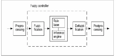
[image:1.595.318.548.229.340.2]There are specific components characteristic of a fuzzy logic controller (FLC) to support a design procedure. Figure 1 shows the controller between the preprocessing block and post processing block. [9]
Fig 1: Structure of fuzzy logic controller
2.1
Preprocessing
The inputs are most often hard or crisp measurement from some measuring equipment rather than linguistic. A preprocessor, the first block in Figure 1 shows the conditions the measurements before enter the controller [9].
2.2
Fuzzification
The first block inside the controller is fuzzification which converts each piece of input data to degrees of membership by a lookup in one or several membership functions. The fuzzification block matches the input data with the conditions of the rules to determine. There is degree of membership for each linguistic term that applies to the input variable [9].
2.3
Rule Base
The collection of rules is called a rule base. The rules are in “If Then” format and formally the If side is called the conditions and the Then side is called the conclusion. The computer is able to execute the rules and compute a control signal depending on the measured inputs error (e) and change in error (dE). In a rule based controller the control strategy is stored in a more or less natural language. A rule base controller is easy to understand and easy to maintain for a non- specialist end user and an equivalent controller could be implemented using conventional techniques [9].
2.4
Defuzzification
2.5
Postprocessing
The postprocessing block often contains an output gain that can be tuned and also become as an integrator [9].
2.6
Mamdani fuzzy inference
The most commonly used fuzzy inference technique is the so-called Mamdani method(Mamdani & Assilian, 1975) which was proposed, by Mamdani and Assilian, as the very first attempt to control a steam engine and boiler combination by synthesizing a set of linguistic control rules obtained from experienced human operators
It uses the error e (k) and the variable error d (k) to produce changes in function of the output driver (may be μ (k) or Dμ (k)).
e(k) is defined as the point minus the output:
3.
APPROACH
[image:2.595.316.548.75.234.2]For this work, we aim to demonstrate the results through the design and simulation of a PID controller and "fuzzy" in order to learn a little more about the design of controllers and determine the main characteristics of intelligent control by compared to a conventional control. The following figure shows the full system.
Fig 2. General block diagram of the system
We will focus on the design of fuzzy controllers, PID controllers are simple, and our goal is to analyze the results, the transfer function of the universal motor was taken from a real system. The tests were carried out with a classic controller.
4.
REGULATOR
PID
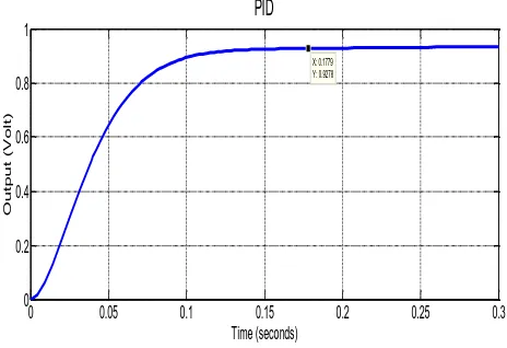
Firstly, the design of a PID controller, we have to analyze the behavior of the closed loop system in order to understand the system and to define the design parameters to proceed. In Figure 3, it can be seen the output of the closed loop system with a single step.
Fig 3. System with PID controller
[image:2.595.320.556.305.462.2]Another very important parameter is the output of the controller, namely the signal from the input of the actuator, Figure 4 display output of PID regulator.
Fig 4. PID controller output
5.
FUZZY
CONTROLLER
To design the fuzzy controller is taken into account two different approaches (Fuzz1 and Fuzz2), ie two rules with different sets have been defined to show that these controllers can be done in several ways. and solutions that may be better than others.
5.1
first approach
The following linguistic variables are:
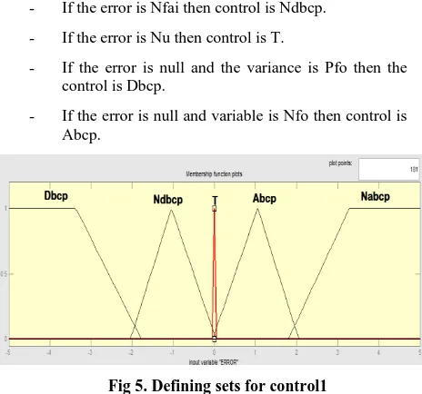
Error inputs : strong negative ( Nfo) , small negative ( Nfai), Null (Nu), strong positive ( Pfo), small positive ( Pfai).
Variation of error: strong negative (Nfo), strong positive ( Pfo).
Output: decrease much (Dbcp), Not decrease much (Ndbcp), Set (T), increase much (Abcp), Not increase much (Nabcp).
Rules : the rules are defined as follows
- If the error is Pfai then control is Abcp.
0 0.05 0.1 0.15 0.2 0.25 0.3
0 0.2 0.4 0.6 0.8 1
X: 0.1779 Y: 0.9278
Time (seconds)
O
u
t
p
u
t
(
V
o
lt
)
PID
0.1 0.2 0.3 0.4 0.5 0.6 0.7
0 0.2 0.4 0.6 0.8 1 1.2 1.4 1.6
Time (seconds)
A
m
p
li
tu
d
e
(
vo
lt
)
[image:2.595.56.284.456.523.2]0 0.05 0.1 0.15 0.2 0.25 0.3 -1
-0.5 0 0.5 1 1.5
Time (seconds)
Am
plit
ude
(Volt
)
output fuzzy controller
- If the error is Nfai then control is Ndbcp. - If the error is Nu then control is T.
- If the error is null and the variance is Pfo then the control is Dbcp.
[image:3.595.56.288.73.290.2]- If the error is null and variable is Nfo then control is Abcp.
Fig 5. Defining sets for control1
[image:3.595.318.562.75.244.2]The fuzzy controller Simulink diagram used in our simulation is shown in Fig 6.
Fig 6. Closed loop system using fuzzy controller.
From the simulation, the following results were obtained.
[image:3.595.315.550.319.526.2]Fig 7. Output of fuzzy controller 1.
Fig 8. Response system with fuzzy controller 1.
5.2
Second approach
In the second approach, we only used the error as an input. The configurations used in FLC2 is presented as follow:
Inputs (error): negative (N), null (Nu), positive (P). Output: decrease (D), constant (S), increase (I). Rules : the rules are defined as follows - If the error is N then control is D. - If the error is Nu then control is S. - If the error is P then control is I.
Fig 9. Defining sets for control2
In simulink, FLC2 diagramm is shown in Fig.10.
Fig 10. Closed loop system using fuzzy controller 2.
0 0.05 0.1 0.15 0.2 0.25 0.3
0 0.2 0.4 0.6 0.8 1 1.2 1.4
Time (seconds)
Am
plit
ude
(Volt
)
[image:3.595.52.290.327.449.2] [image:3.595.40.275.502.664.2] [image:3.595.317.563.558.690.2]Fig 11. Response system with fuzzy controller 2.
Fig 12. Output of fuzzy controller 2
[image:4.595.60.292.259.421.2]The Results of the analysis with a comparison of the three controllers is presented in the following figures.
Figure 13. Comparison between regulators PID and Fuzzy1 Fuzzy2 .
Figure 14. Comparison between PID and fuzzy1 fuzzy2 at different stages.
Different speed and load requirements are applied to the system and the performances are taken for analysis and comparisons. The error, e, the difference between reference and actual value, is commonly characterized into several quantities.
The performance indices used here are: 1. The Integral of Squared Error (ISE)
2. The Integral of Absolute Error (IAE)
3. The Integral of Time Multiply Squared Error (ITSE)
4.
The Integral of Time multiply Absolute Error (ITAE)Comparison of PID controller and Fuzzy logic controller step response specifications are tabulated in the following two tables.
Table 1: Performance indexes of PID and fuzzy logic controllers
0 0.02 0.04 0.06 0.08 0.1 0.12 0.14 0.16 0.18 0.2 0 0.2 0.4 0.6 0.8 1 1.2 1.4 Time (seconds) A m p li tu d e (V o lt )
0 0.05 0.1 0.15 0.2 0.25
-4 -3 -2 -1 0 1 2 3 4 Time (seconds) A m p li tu d e ( V o lt )
Time Series Plot:
0 0.05 0.1 0.15 0.2 0.25 0.3 0.35 0.4
0 0.2 0.4 0.6 0.8 1 1.2 1.4 Time (seconds) A m p li tu d e ( V o lt ) Outputs Fuzzy 2 Fuzzy 1 PID
0 1 2 3 4 5 6
0 0.5 1 1.5 2 2.5 3 3.5 4 4.5 Time (seconds) A m p li tu d e ( V o lt ) Fuzzy 2 Fuzzy 1 PID
2 2.2 2.4 2.6 2.8 3 3.2
2 2.5 3 3.5 4 Time (seconds) A m p lit u d e ( V o lt ) Fuzzy 2 Fuzzy 1 PID
PID FLC1 FLC2
ISE 0.031 0.035 0.017
IAE 0.092 0.059 0.028
ITSE 0.00176 0.00089 0.00020
[image:4.595.301.549.621.710.2]6.
ANALYSIS
OF
RESULTS
In fuzzy control systems it can be defined several ways to execute fuzzy control, where some are better than others, it can be seen that several rules does not always give the best results, the results of the Fuzzy controller are much better than PID (table 1), and PID controller do not vary with the different stages, namely behaves the same magnitude over the entire operating range, the greater the error in the steady state was lower (close to zero) but an error of 2% does not mean a big thing in this type of installation, and finally the two systems are effective against disturbances.
All this can be seen in Figures 13 and 14 that illustrates the different controllers designed are effective in managing shocks and stabilize to retain the reference to the disturbance input.
7.
CONCLUSION
In the design of fuzzy controllers it is more important to know how the system works as it is clear in the dynamic case; a set of rules can be created to achieve the desired results. Comparing the two fuzzy controllers that have been developed for the plant can be seen that the proper functioning of the controller gives a good definition of rules and the allocation sets. It was obvious that the second pilot despite having fewer rules, a better response to step changes and very close to zero (static error).
for simple systems, it is recommended to use conventional drivers, because they are very simple and fairly well controlled, if the opposite and the system is very complicated, and you can not get the model; the system of nonlinear fuzzy controllers is a very good alternative.
8.
REFERENCES
[1] S. Rafa et all, “Implementation of a new fuzzy vector control of induction motor”,ELSEVIER,ISA Transactions53 (2014). 744–754.
[2] J Fonseca , L. Afonso, S. Martins, C. Couto, ‘’Fuzzy logic speed control of an induction motor’’,ELSEVIER,Microprocessors and Microsystems 22 (1999) 523–534.
[3] G. Rigatos, ‘’Adaptive fuzzy control of DC motors using state and output feedback’’,ELSEVIER,Electric Power Systems Research 79 (2009) 1579–1592.
[4] J.M. Mendel, Fuzzy Logic systems for engineering: A tutorial,Proceedings of the IEEE, 83 3, 1995, pp. 345– 377.
[5] RJager, Fuzzy logic in control, PhDThesis,Delftuniversity, Holland,1995.
[6] G.C. Sousa, B.K. Bose, J.G. Cleland, Fuzzy logic based on-line efficiency optimisation control of an indirect vector controlled inductionmotor drive, IEEE, Trans. On industrial electronics 42 (2) (1995)192–198.
[7] J. Fonseca, J.L. Afonso, J.S. Matins, C. Couto, Evaluation of neuralnetworks and fuzzy logic techniques applied to the control of electrical machines, Proceedings of the 5th UK mechatronics forum international conference,Portugal, 2, 1996, pp. 15–20.
[8] J.L. Afonso, J. Fonseca, J.S. Martins, C. Couto, Fuzzy logic techniques applied to the control of a three-phase induction motor, ISIE’97-IEEE International symposium on Industrial Electronics, Guimaraes, Portugal, July 7-11, 1997, IEEE Catalog number:97TH8280, ISBN:07803-3936-3, pp. 1179–1184.