Improved Robust Algorithm for Exemplar based Image
Inpainting
Ankur G. Patel
Assi.Prof. in Computer Sci.&Engg.at MGITER,Navsari, Gujarat, India
Ankit D. Prajapati
Assi.Prof. in Computer Sci.&Engg. at Faculty of Engg.Technology & Research Bardoli, Gujarat.
Pritika H. Patel
Assi.Prof. in Computer Sci.&Engg.at MGITER,Navsari, Gujarat, India
ABSTRACT
Image Inpainting is technique in which mainly used to filling the region which are damaged and want to recover from unwanted object by collecting the information from the neighbouring pixels. Image inpainting technique has been widely used for reconstructing damaged old photographs and removing unwanted objects from images. In this paper, we present an improved robust algorithm for exemplar based inpainting method by modifying the distance function. The method proved to be effective in removing large objects from an image, ensuring accurate propagation of linear structures, and eliminating the drawback of “garbage growing” which is a common problem in other methods. Experimental results show that our method improves the quality of image inpainting compared with the conventional exemplar-based image completion algorithms.
Keywords
Exemplar, Texture Synthesis, Inpainting, PDE, image gradient etc.
1.
INTRODUCTION
There are lots of advantages multimedia instruments in today’s world peoples are clicking lots of images of theirs and also they were trying to preserve their past pictures. And as the time goes on those pictures got damaged.(cracks, starches, image data loss) Inpainting is the art of restoring lost parts of an image and reconstructing them based on the background information. In the real world, many people need a system to recover damaged photographs, designs, drawings, art works etc. damage may be due to various reasons like scratches, overlaid text or graphics etc. [1]
Inpainting technique has many applications such as, object removal in digital photos, removal of occlusions (date, stamps, logo etc.), such as large unwanted regions, red eye correction, super resolution, restoration of old films and paintings etc. [2]Another use of image inpainting is in creating special effects by removing unwanted objects from the image. Unwanted objects may range from microphones, ropes, some unwanted person and logos, stamped dates and text etc. in the image. During the transmission of images over a network, there may be some parts of an image that are missing. These parts can be reconstructed using image inpainting. Many works on Inpainting have been proposed these recent years [1]. The image is to decompose the original image into a structure and a texture image. Reconstruction of each image is performed separately.The missing information in the structure component is reconstructed using a structure Inpainting algorithm, while the texture component is repaired by an
2.
RELATED WORK ON EXEMPALR
BASED INPAINTING
[13]As it was shown in above that PDE based Inpainting algorithms are not sufficient for faithfully reconstructing textured images, nor images with large missing areas. Thus, when Inpainting is done with an image restoration purpose in mind, more complex techniques are required, as paintings are composed of both structures and textures. Exemplar-based Inpainting methods can overcome this drawback, being able to provide reasonably good quality results, even for large gaps, by combining the isophote driven Inpainting with texture synthesis. The reconstructed visual quality and the reasonability of the filled image are mainly influenced by the filling order. So, we conclude that better performance is obtained using developing a robust priority function. Exemplar based Inpainting iteratively synthesizes the target region, by the most similar patch in the source region.[3] According to the filling order, the method fills structures in the missing regions using spatial information of neighboring regions. This method is an efficient approach for reconstructing large target regions. Generally, an exemplar-based Inpainting algorithm includes the following three main steps:
Fig.2. Notation diagram for Exemplar based inpainting [13] In patch
p,
thenp is the normal to the contour ofthe target region and is the isophotes at point p. The whole image is denoted with I.
First take an input image, the user selects a target region, Ω, to be removed or filled. The source region,, may be defined as the entire image minus the target region (= I - Ω), as a dilated band around the target region, or it may be manually specified by the user. Here a window size 9 x 9 pixels.Once these parameters are determined, the region-filling proceeds automatically.
pixel has been filled.The algorithm, patches along the fill front are also given a temporary priority value, which determines the order in which they are filled. Then, algorithm iterates the following three steps until all pixels have been filled:
1) Computing patch priorities.
Filling order depends on the priority values which is assigned to each patch on the fill front. Given a patch p centered at
the point p for somep (see fig.2), we define its priority P (p) as the product of two terms:
)
(
)
(
)
(
p
C
p
D
p
P
(1)
Here C (p) is the confidence term and D (p) is the data term, and they are given as follows:
p I q p
q C
p C
( )) (
)
( ,
p p n
I p D
. ) (
(2)
Where p is the area ofp ,is a normalization factor
(e.g.,=255 for a typical grey-level image),npis a unit
vector orthogonal to the front in the point p and denotes the orthogonal operator. The priority P(p) is computed for every border patch, with distinct patches for each pixel on the boundary of the target region. During initialization, the function C(p) is set to C (p) = 0 .p
and C (p) = 1 . pI
Figure 3: Visualizations of exemplar-based inpainting process.[13] (a) Original image shows sources and target region as well as the boundary contour (b)Patch that was given the highest priority(c) Candidate patches q’ and q′′ (d) The patch q′ is filled in with the best matching
patch.
2) Propagating texture and structure information. Search the source region to find the patch which is most similar topˆ.
)
,
(
min
arg
ˆ ˆˆ p q
q
qd
(3)Where the distance d(a,b)between two generic patches is
defined as the sum of squared differences (SSD) of the already filled pixels in the two patches.
3) Updating Confidences values
In which the boundaryof the target region and the required information for computing filling priorities are updated.
) ˆ ( )
(q C p
C
qpˆ
(4)
In this paper present, the new priority function is able to resist undesired noises.
3.
EXISTING ROBUST ALGORITHM
FOR EXEMPLAR BASED INPAITING
ALGORITHM
[7]In Criminisi’s original algorithm [13], the priority function P(p) for each unfilled pixel pδΩ is defined as the product of two terms as follows.
)
(
)
(
)
(
p
C
p
D
p
P
(5)
Where C (p) is called the confidence term and D (p) is called the data term. The confidence term is used to capture the texture property and the data term represents
the structure characteristic.
In existing method they found result that the confidence value drops rapidly to zero as the filling process proceeds, which makes the computed priority values undistinguishable, and in turn, results in incorrect filling
orders.
Therefore, first modify the priority function [7] to an additive rather than a multiplicative form as follows:
)
(
)
(
)
(
P
C
p
D
p
P
(6)
The resulting treatment of the confidence and the data terms is more balanced. However, direct combination of C(p) and D(p) is still unreasonable due to the significant differences in their curve behaviour. Therefore, they use a regularizing function [7] RC(p) to smooth the curve of the confidence term C(p) to match that of the data term as follows.
R
(p) = (1−ω) ×
C
(
p
) +ω
C
, 0 ≤ω ≤1,
(7)Where ω is the regularizing factor for controlling the curve smoothness. So the value of the new confidence term is regularized to [w, 1].
Finally the robust priority function Rp(p) as define follow:
)
(
.
)
(
.
)
(
p
p
D
p
RP
c
R
, 0<=α
, β <=1, (8)Where α and β are respectively the component weights of the confidence and the data terms. Note that α +β =1.
image itself by parallelizing the curve behaviours of the function component terms.
Step 1.Determine the edge of the patch to be inpainted δΩ; Step 2.Calculate CN (p), D (p) and P (p);
Step3. Find the inpainting block pˆwith the highest priority;
Step 4.Search the image blockpˆ which is best matched with the current blockpˆto be inpainted in the source patch of the image;
Step 5.Update the confidence term C (p) which has been filled;
Repeat the above steps until the inpainting is completed.
4.
IMPROVED ALGORITHM
We find that the similarity measure based only on color is insufficient to propagate accurate linear structures into the target region, and leads to garbage growing. So, we add to this distance function a new term G representing image gradient as an additional similarity metric.
)
(
p qG
G
(8)
Where G is the gradient value for each pixel in the two considering patches. Hence, the similarity function now depends on the difference between the patches according to two criteria, the difference in color and in gradient values. The gradient of an image measure how it is changing. It provides two pieces of information. The magnitude of the gradient tells us how quickly the image is changing while the direction the gradient tells us the direction in which the image is changing most rapidly.
The detail of the algorithm steps are as follows:
1. Computing patch priorities
p I q p q C p C
( ) ) ( ) (
p p n I p D . ) ( (9)Where α,Ip, and np are respectively the normalization
factor.(e.g., α=255),the isophote vector, and the unit vector orthogonal to the front
in the point p.R
(
p
) = (1−ω) ×
C
(p) +ω
C,
0 ≤ω ≤1,
(10)The priority function is defined as the weight sum of regularized confidence term C(p) and new data term D(p). Where α is adjustment coefficient, satisfying 0<w<1. Finally the robust priority function Rp(p) as define follow:
)
(
.
)
(
.
)
(
p
p
D
p
RP
c
R
, 0<=α
, β <=1, (11)Where α and β are respectively the component weights of the confidence and the data terms. Note that α +β =1.
2) Propagating texture and structure information
Search the source region to find the patch which is most
similar to ^ p .
)
,
(
min
arg
ˆ ˆˆ p q
q
p
d
(12)Here the distance d(a,b)between two patches is defined as the sum of squared differences (SSD) of the already filled pixels in the two patches.
A i i bi ai biai I G G
I d
1
2
2 ( )
)
( (13)
Where, G presents the image gradient vector, I is the RGB color vector, D is the distance (the larger d is, the less similar they are), and A is the known pixels number in pˆ .
The source exemplar qˆthe value of each pixel to be filled is copied from its corresponding position.
3) Updating Confidences values
The confidence C (p) is updated in the area delimited bypˆ as follow:
) ˆ ( )
(q C p
C qpˆ
(14)
As filling proceeds, confidence value decrease, indicating that we are less sure of the color values of pixels near the centre of the target region.
5.
EXPERIMENTAL RESULTS
To verify the effectiveness of the proposed variance approach and the improvement on several images and compared the so-obtained results with the conventional approaches.
A. Comparison with Criminisi’s [13], Wang [7] and Our Proposed method
Now we present the comparison of our approach with one presented by Criminisi’s in[13]
, Wang C[7] in and Our Proposed method. The result evaluation is performed by comparing PSNR (the Peak Signal-to-Noise Ratio) between restored image and original image. Generally the higher the PSNR value the larger the similarity of the repaired image to the original. The equation to calculate PSNR as given follows.
M x N y y x u y x u MN MSE 1 1 2 0( , )] ) , ( [ 1 (15) MSE PSNR 2 255 log 10 (16)
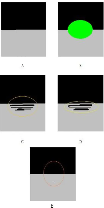
Figure (4): TEST image1 the removal of the big object (A)Input image (B)Inpainted image(C)Results of Criminisi’s (D)Results of a Wang C(E)Our results.
B. Real Life Examples
Now we present a few more examples from real life scenes which are captured by us.
[image:4.595.77.434.73.587.2]Fig 5 shows examples of inpainting using our algorithm. The noise is added randomly to the image and then inpainting was applied. In this figure the structure of the head part is preserved. But the computational time for our algorithm is little longer then [13] and [7].
Table 1. Table captions should be placed above the table
PSNR Ratio
Algo. by Crinisis[13]
Algo.by Wang C[7]
Our Proposed
Method
Image1 52.9556 53.6875 53.7890
Image2 53.9098 52.4212 53.8989
Image3 58.6565 58.8214 59.4560
Figure (5): TEST image2.(A)Input image (B)Inpainted image(C)Results of Criminisi’s (D)Results of a Wang
[image:4.595.213.534.80.675.2]Figure (6): TEST image3.(A)Input image (B)Inpainted image(C)Results of Criminisi’s (D)Results of a Wang
C(E)Our results.
6.
CONCLUTION AND FUTURE WORK
The method proposed by Wang, C [7]]
includes a similarity measure based only on color is insufficient to propagate accurate linear structures into the target region, and leads to garbage growing. The improved method in which image in paint performs accurately by modified distance function a new term G represents using image gradient as a similarity metric. In this method by using gradient as similarity metric accuracy of the image inpainting result can be increased. This algorithm can be used to remove objects from the image in a way that it seems reasonable to the human eye and provide effective image inpainting result and also enhance the performance.
7.
ACKNOWLEDGMENTS
The authors would like to thank to Ankit Prajapati and Pritika Patel for inspiring discussions; and G. Sapiro, M. Bertalmio, D. Capel, A. Criminisi, M.S.Ishi, Prof. Lokesh Singh, Prof. Manish Agrawal for making some of their images available.
8.
REFERENCES
[1] Ankur patel, Shashwat kumar and Ankit parajapati, “Analysis of Exemplar based Image inpainting,”International Journal of Computer Sciences and Information Technology. Vol.5 (1), 2014, pp. 800-804.
[2] Bertalmio M, Vese L, Sapiro G, Osher S. Simultaneous structure and texture image inpainting,” IEEE Transactions on Image Processing, 2003, 12, 882-889. [3] Rane S, Sapiro G, Bertalmio M. Structure and texture
filling of missing image blocks in wireless transmission and compression applications. In IEEE. Trans. Image Processing, 2002.
[4] Chan T, Shen J. Local inpainting models and TV inpainting, SIAM Journal on Applied Mathematics, 2001, 62, 1019-1043.
[5] Chan T, Shen J. Non texture inpainting by curvature-driven diffusions, Journal of Visual Communication and Image Representation, 2001, 4, 436-449
[6] Heeger DJ, Bergen JR. Pyramid-Based Texture Analysis/Synthesis. In proceedings Of ACM Conf. Comp. Graphics (Siggraph),Los Angeles, Ca, 1995, 29, 229-233
[7] Cheng W, Hsieh C, Lin S, Wang C, Wu J. “Robust algorithm for exemplar based image inpainting”in Proceedings of International Conference on Computer Graphics, Imaging and Visualization, 2005, 64-69. [8] Wong, Orchard J. A nonlocal means approach to
exemplar-based inpainting, in Proceedings of the 15th IEEE International Conference on Image Processing, 2008, 2600-2603
[9] Z. Xu and S. Jian, “Image inpainting by patch propagation using patch sparsity,” IEEE Transactions on Image Processing, Vol. 19, 2010, pp. 1153-1165. [10] Alexei A. Efros and Thomas K. Leung, “Texture
Synthesis by Non-Parametric Sampling”, IEEE International Conference on Computer Vision, 1033– 1038, 1999 .
[11] A. Wong and J. Orchard, “A nonlocal-means approach to examplar-based inpainting,” presented at the IEEE Int. Conf. Image Processing, 2008
[12] W. Cheng, C. Hsieh, S. Lin, C. Wang, and J. Wu, “Robust algorithm for exemplar-based image inpainting,” in Processing of International Conference on Computer Graphics, Imaging and Visualization, 2005, pp. 64-69.
[13] A. Criminisi, P. Pérez, and K. Toyama, “Region filling and object removal by exemplar-based image inpainting,” IEEE Trans. Image Process., vol. 13, no. 9, pp. 1200–1212, Sep. 2004.
[14] Zhou, J. & Kelly, A. R. 2010. Image Inpainting based on local optimization. International Conference on Patteren Recognitions (ICPR).
[image:5.595.70.287.76.508.2]