http://dx.doi.org/10.4236/eng.2014.61005
Strip Thickness Control of Cold Rolling Mill with Roll
Eccentricity Compensation by Using
Fuzzy Neural Network
Waleed I. Hameed, Khearia A. Mohamad Department of Electrical Engineering, University of Basrah, Basrah, Iraq
Email: waleed_ishaq5@yahoo.com
Received November 12,2013; revised December 12, 2013; accepted December 19, 2013
Copyright © 2014 Waleed I. Hameed, Khearia A. Mohamad. This is an open access article distributed under the Creative Commons Attribution License, which permits unrestricted use, distribution, and reproduction in any medium, provided the original work is properly cited. In accordance of the Creative Commons Attribution License all Copyrights © 2014 are reserved for SCIRP and the owner of the intellectual property Waleed I. Hameed, Khearia A. Mohamad. All Copyright © 2014 are guarded by law and by SCIRP as a guardian.
ABSTRACT
In rolling mill, the accuracy and quality of the strip exit thickness are very important factors. To realize high accuracy in the strip exit thickness, the Automatic Gauge Control (AGC) system is used. Because of roll eccen-tricity in backup rolls, the exit thickness deviates periodically. In this paper, we design PI controller in outer loop for the strip exit thickness while PD controller is used in inner loop for the work roll actuator position. Also, in order to reduce the periodic thickness deviation, we propose roll eccentricity compensation by using Fuzzy Neural Network with online tuning. Simulink model for the overall system has been implemented using MAT-LAB/SIMULINK software. The simulation results show the effectiveness of the proposed control.
KEYWORDS
Cold Rolling Mill; Thickness Control; Roll Eccentricity; Fuzzy Neural Network; Eccentricity Compensation
1. Introduction
Rolling strip is widely used for automobile manufactur-ing, food packagmanufactur-ing, household electric appliances, ma-chinery, light industry, instruments, communications, mil-itary affairs and other fields [1]. The design of a control-ler in the cold rolling system that can improve the beha-vior and response of the plant to specific performance constraints can be a tedious and challenging problem in many control applications [2]. In order to meet increasing demand for the high precision of strip thickness, various types of Automatic Gauge Control (AGC) methods have been developed for hot or cold mill processes. The Brit-ish Iron and Steel Research Association (B1SRA) AGC method based on the gauge meter principle and the feed forward AGC method using the delivery time of the strip have been widely utilized in steel rolling mills [3].
Strip products thickness precision is an important quality parameter. But the export thickness appears as the periodical fluctuation in the practical production because of the roll eccentricity thermal expansion of rolls and the
overcome [5]. In this paper, PI and PD controller has been used to control the output thickness and hydraulic servo system respectively. Also we propose roll eccen-tricity compensation by using Fuzzy Neural Network. The paper is organized as follows: in Section 2, a brief description of the cold rolling process is presented. In Section 3, a mathematical model has been driven for sin-gle-stand cold rolling mill. In Section 4, architecture and learning algorithm of Fuzzy Neural Network have been presented. In Section 5, thickness control with roll ec-centricity compensation has been proposed. In Section 6, simulation results have been presented. Finally, section 7 presents the conclusions.
2. Cold Rolling Process Overview
The tandem cold rolling of metal strip is one process in a sequence of processes performed to convert raw mate-rials into a finished product [6]. It is a deformation process in which the thickness of the strip is reduced by compressive forces exerted by two opposing rolls (two or four-high arrangement of rolled products). The roll ro-tates as illustrated inFigure 1 to pull and simultaneously squeeze the strip between them [7].
[image:2.595.65.536.498.717.2]The strip is passed through four pairs of independently driven work rolls, with each work roll supported by a backup roll of larger diameter. As the strip passes through the individual pairs of work rolls, the thickness is succes-sively reduced. The reduction in thickness is caused by very high compression stress in a small region (denoted as the roll gap, or the roll bite) between the work rolls. In this region the metal is plastically deformed, and there is slipping between the strip and the work roll surface. The necessary compression force is applied by hydraulic rams, or in many older mills by a screw arrangement driven by an electric motor [6].
Figure 1. The rolling process (flat rolling).
3. Mathematical Model of Cold Rolling
Process
3.1. Force Equation
Define the theory for prediction of specific roll force is central to the development of a model for tandem cold rolling. Referring to Figure 2, which approximately represents the strip in the roll bite area, the incoming strip is of thickness hin at its centerline and is moving toward the roll bite with speed vin. The strip exits the roll bite with thickness hout at its centerline and with speed vout [6,7]. In flat rolling, the strip is squeezed between two rolls so that its thickness is reduced by an amount called the draft [7]:
in out
d =h −h (1)
where d = draft, mm.
The rolling strip contact length can be approximated by [8]:
(
in out)
L= R h −h (2)
The true strain experienced by the strip in rolling is based on before and after stock thickness. In equation form:
ln in out
h h
ε= (3)
The true strain can be used to determine the average flow stress Yavg applied to the strip material in flat roll-ing:
1 n avg
K Y
n
ε
=
+ (4)
where K = the strength coefficient, MPa; and n is the strain hardening exponent.
The force F required to maintain separation between the two rolls can be calculated based on the average flow stress experienced by the strip material in the roll gap [7,8]. That is,
avg
F =Y wL (5)
where w = width of the strip, R is radius of work roll.
3.2. Output Thickness Equation
In the cold rolling process and the precision is strip thickness of cold rolled strips of key quality products. Conventional Automatic roll gap Control (where Gauge, AGC) system used for Automatic correction strip thick-ness accuracy [9]. One of the conventional control strat-egy of strip thickness is using of BISRA measurements to infer strip thickness. This relationship (more often referred to as “gaugemeter” or “BISRA gaugemeter”) has been used to estimate the thickness of the strip exiting the roll bite without requiring a direct measurement. Re-liable direct measurement of strip thickness at the exit of the roll bite requires expensive and complex equipment [6]. The relationship between the work roll gap(S), the exit strip thickness hout, and the roll force(F) generated at the roll stand is expressed as [3,10]:
out
F h S
M
= + (5)
where M is mill modulus
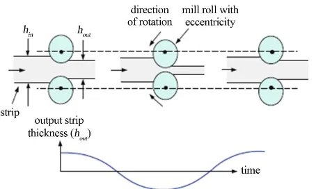
The BISRA relationship is used to develop a thickness feedback signal for closed-loop control. To control the output thickness, the motion of hydraulic cylinder con-trolling the roll gap position is such that produces the desired output thickness [6]. Roll eccentricities are caused by axial deviations between the roll barrel and the roll necks due to irregularities in the mill rolls and/or roll bearings [11]. These irregularities cause cyclic deviations in the strip thickness at the output of a mill stand. Figure 3 depicts the effects of eccentricity on the output strip thickness [6].
When the entry strip is passed through the roll stand with the velocity vin, the disturbance ∆H is expressed as:
2π sin in d
d v
H A t
L
∆ =
(6)
where Ad and Ld are the magnitude and period of thickness deviation respectively [3]. Roll eccentricity is not part of the controller but must be considered to be consistent with data reported from operating mills which
Figure 3. Effects of roll eccentricity on output strip thick-
ness.
usually includes its effects. The eccentricity components remaining in the mill exit thickness after compensation. In the model, roll eccentricity modifies Equation (5) as [12]:
out
F
h S e
M
= + + (7)
where e is the roll eccentricity.
4. Basic Principle of Fuzzy-Neural Network
A promising approach to obtaining the benefits of both fuzzy systems and neural networks and solving their re-spective problems is to combine them into an integrated system. The integrated system will possess the advan-tages of both neural networks (e.g., learning abilities, optimization abilities, and connectionist structures) and fuzzy systems (e.g., humanlike IF-THEN rules thinking and ease of incorporating expert knowledge). In this way, we can bring the low-level learning and computational power of neural networks into fuzzy systems and also high-level, humanlike IF-THEN rule thinking and rea-soning of fuzzy systems into neural networks. Thus, neural networks can improve their transparency, making them closer to fuzzy systems, while fuzzy systems can self-adapt, making them closer to neural networks. Inte-grated systems can learn and adapt [13]. The different integrated neurofuzzy models make use of the comple-mentarities of neural networks and fuzzy inference sys-tems implementing a Mamdani or Takagi Sugeno fuzzy inference system [14].4.1. Architecture of Fuzzy Neural Network (FNN)
[image:3.595.311.538.82.218.2]Figure 4. Architecture of FNN.
Input Layer I: Input layer transmits the input linguis-tic variables xn to the output without changed.
Hidden Layer II: Membership layer represents the input values with the following Gaussian membership functions [17]:
(
)
22 1 exp
2 j ij i
j
ij
x c
s µ = − −
(8)
where cij and sij
(
i=1, 2,, ;n j=1, 2,,m)
, respec-tively, are the mean and standard deviation of the Gaus-sian function in the jth term of the ith input linguistic variable xj to the node of this layer.Hidden Layer III: Rule layer implements the fuzzy inference mechanism, and each node in this layer multip-lies the input signals and outputs the result of the product. The output of this layer is given as [17]:
n i
i j
j
φ =
∏
µ (9)where φi represent the th
i output of rule layer.
Output Layer IV: Layer four is the output layer, and nodes in this layer represent output linguistic variables. Each node yo
(
o=1,,No)
, which computes the output as:m o o i i i
y =
∑
wφ (10)where wio represent the th
i output weight of rule layer.
4.2. Learning Algorithm for FNN Controller
The parameter of the FNN controller presented in Figure 4 should be adjusted according to the following equa-tions [18]:
(
1)
( )
i i w
i
E
w k w k
w
η ∂
+ = −
∂ (11)
(
1)
( )
ij ij c
ij E c k c k
c
η ∂
+ = −
∂ (12)
(
1)
( )
ij ij s
ij E s k s k
s
η ∂
+ = −
∂ (13)
The goal of the learning algorithm is to minimize the error between the desired output thickness h k
( )
and the output thickness of the stand h ko( )
. In the present work the Least Mean Square (LMS) function will be used to define a criterion for the error E.( )
1² 2
E k = e (14)
( )
o( )
e=h k −h k (15)
where η is the learning rate for each parameter in the system, i=1, 2,,n and j=1, 2,,m.
5. Design of Thickness Control with Roll
Eccentricity Compensation
Figure 5. Block diagram of exit thickness control.
Figure 6. Simulink model of thickness control.
used as APC.
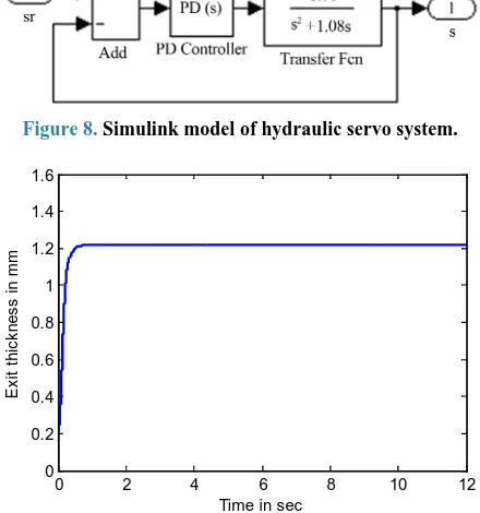
The simulink model of force equation is shown in Figure 7. Also the simulink model of hydraulic servo system is shown in Figure 8[20].
6. Simulation Results
A program written in Matlab code is used to simulate FNN using Matlab S-function programming. In the primes part, the number of membership functions for each input are five. So, the number of weights in the consequence part is also five. The mill and strip proper-ties is shown in Table 1.Without roll eccentricity effect, Figure 9 shows the exit thickness when the desired thickness is 1.22 mm. When roll eccentricity is taken into account, the exit thickness is shown in Figure 10. As shown in this figure, the disturbance (∆H) which has Amplitude Ad appear periodically in the exit thickness and this is drawback that effect on the accuracy and qual-ity of the strip exit thickness. The compensation signal (c) which is produced by FNN added to the desired position roll gap to reduce the periodic deviation in the exit thickness. This is shown clearly in Figure 11 which
Figure 7. Simulink model of force equation.
Table 1. The mill and strip properties.
Parameter Dimension
Work roll radius 250 mm
Mill modulus 3921 kN/mm
Strip width 600 mm
Entry Thickness 1.52 mm
Exit thickness 1.22 mm
strength coefficient 240 MPa
strain hardening exponent 0.15
d
A 0.05 mm
in
v 2 m/s
d
L 2 m
Figure 8. Simulink model of hydraulic servo system.
Figure 9. Exit thickness without roll eccentricity effect.
Figure 10. Exit thickness with roll eccentricity effect.
Figure 11. Exit thickness after compensation the effect of
roll eccentricity.
Figure 12. Exit thickness with and without compensation.
results, It is found that FNN is robust in that it eliminate the periodic thickness deviation considerably.
7. Conclusion
In this paper, the mathematical model of single-stand cold rolling mill is developed and PI controller has been used to control exit thickness of the strip. We propose FNN in order to reduce the effect of roll eccentricity. The error between the reference exit thickness and output thickness of stand is used as trajectory to adapt the primes part and the consequence part of the FNN so that the error goes toward zero. The output of FNN is added to the desired position roll gap to reduce periodic devia-tion in the output thickness. As we have shown in the simulation results, the performance of proposed method is good.
REFERENCES
[1] G. Zheng and Q.-Q. Qu, “Research on Periodical Fluctua-tions Identification and Compensation Control Method for Export Thickness in Rolling Mill,” IEEE Proceedings of the Eighth International Conference on Machine Learning and Cybernetics, Baoding, 12-15 July 2009, pp. 1972-1977.
[2] K. M. Takami, J. Mahmoudi and E. Dahlquist, “Adaptive Control of Cold Rolling System in Electrical Strips Pro-duction System with Online-Offline Predictors,” Springer International Journal of Advanced Manufacturing Tech-nology, Vol. 50, No. 9, 2010, pp. 917-930.
http://dx.doi.org/10.1007/s00170-010-2585-7
[3] G. Hwang, H.-S. Ahn, D.-H. Kim, T.-W. Yoon, S.-R. Oh and K.-B. Kim, “Design of a Robust Thickness Controller for a Single-Stand Cold Rolling Mill,” IEEE Proceedings of the International Conference on Control Applications,
Dearborn, 15-18 September 1996, pp. 468-473.
[4] Mishra, et al., “Design of Hybrid Fuzzy Neural Network for Function Approximation,” Journal of Intelligent Learning Systems and Applications, Vol. 2, No. 2, 2010, pp. 97-109. http://dx.doi.org/10.4236/jilsa.2010.22013
[5] K. Naga Sujatha and K. Vaisakh, “Implementation of Adaptive Neuro Fuzzy Inference System in Speed
Con-0 2 4 6 8 10 12
0 0.2 0.4 0.6 0.8 1 1.2 1.4 1.6
Time in sec
E
x
it
t
h
ic
k
n
e
s
s
i
n
m
m
0 2 4 6 8 10 12 0
0.2 0.4 0.6 0.8 1 1.2 1.4 1.6
Time in sec
E
x
it
t
h
ic
k
n
e
s
s
i
n
m
[image:6.595.62.282.100.335.2]trol of Induction Motor Drives,” Journal of Intelligent Learning Systems and Applications, Vol. 2, No. 2, 2010, pp. 110-118.http://dx.doi.org/10.4236/jilsa.2010.22014
[6] J. Pittner and M. A. Simaan, “Tandem Cold Metal Roll-ing Mill Control UsRoll-ing Practical Advanced Methods,” Springer-Verlag, New York, 2011.
http://dx.doi.org/10.1007/978-0-85729-067-0
[7] Mikell P. Groover, “Fundamental of Modern Manufac-turing,” John Wiley & Sons, Hoboken, 2007.
[8] M. Kutz, “Mechanical Engineers’ Handbook Manufactu-ringand Management,” John Wiley & Sons, Hoboken, 2006.
[9] B. Xu and P. Qian “Application of Adaptive Strategy Based on Model Prediction for the Stripe Thickness in Cold Rolling,” IEEE International Conference on Me-chanic Automation and Control Engineering, 2010, pp. 3278-3281.
[10] S.-B. Tan and J.-C. Liu, “Research on Mill Modulus Control of Strip Rolling AGC Systems,” IEEE Interna-tional Conference on Control and Automation, Guang zhou,May 30-June 1 2007, pp. 497-500.
[11] A. Kugi, W. Haas, K. Schlacher, K.Aistleitner, H. M. Frank and G. W. Rigler, “Active Compensation of Roll Eccentricity in Rolling Mills,” IEEE Transactions on In-dustry Applications, Vol. 36, No. 2, 2000, pp. 625-632.
http://dx.doi.org/10.1109/28.833781
[12] J. Pittner and M. A. Simaan, “An Optimal Control Me-thod for Improvement in Tandem Cold Metal Rolling,”
IEEE Transactions on Industry Applications Annual Meeting, 2007, pp. 382-389.
[13] C.-T. Li and C. S. G. Lee, “Neural Fuzzy Systems: A Neuro-Fuzzy Synergism to Intelligen,” Prentice-Hall,
New Jersey, 1996.
[14] A. Abraham, “Adaptation of Fuzzy Inference System Using Neural Learning,” Springer-Verlag, Berlin, Hei-delberg, 2005.
[15] M. S. Mostafa, M. A. El-Bardini, S. M. Sharaf and M. M. Sharaf, “Fuzzy Neural Networks for Identification and Control of DC Drive Systems,” IEEE International Con-ference on Control Applications, Vol. 1, 2004, pp. 598- 603.
[16] A. ThamerRadhi, “Power System Protection Using Fuzzy Neural Petri Net,” Ph.D. Thesis, Basrah University, Iraq, 2012.
[17] S. A. H. A. Kareem, “Fuzzy Neural and Fuzzy Neural Petri Nets Control for Robot Arm,” MSc. Thesis, Basrah University, Iraq, 2010.
[18] Y. I. Al-Mashhadany, “Modeling and Simulation of Adaptive Neuro-Fuzzy Controller for Chopper-Fed DC Motor Drive,” IEEE Applied Power Electronics Collo-quium (IAPEC), 2011, pp. 110-115.
[19] M. Dong, C. Liu and G. Y. Li, “Robust Fault Diagnosis Based on Nonlinear Model of Hydraulic Gauge Control System on Rolling Mill,” IEEE Transactions on Control Systems Technology, Vol. 18, No. 2, 2010, pp. 510-515.
http://dx.doi.org/10.1109/TCST.2009.2019750