A Challenging Demand Side Power Management through
Smart Embedded Meter System
Muhammad Naeem
Department of ComputerScience
The University of Lahore Sargodha campus
Rao Kamran Khushnood
Department of ComputerScience
The University of Lahore Sargodha campus
Sobia Arshad
Department of ComputerScience
The University of Lahore Sargodha campus
ABSTRACT
A typical smart meter is more than a traditional meter which calculates the real time consumption of electricity and also generates the electricity bill. The smart grids are developed at the back end to support the smart meter. Smart grid makes electricity delivery system more flexible, intelligent, smart, reliable and economical. A variety of technologies are available to make a grid station as smart like smart meter, electric vehicles EVs, energy storage etc. To change a smart grid from concept to reality, it needs a collaboration, integration and interoperability between a sequence of resources like generation, transmission, distribution, communication, consumer markets and service providers.The motivation of this problem is to introduce the mechanism for load management that will be acceptable and easily adopted. The proposed smart embedded meter system will calculate the final consumer load. In case of violation it will ask to set high priority appliance.
General Terms
Smart Meter, Smart Grid, Smart Grid Web Portal, Automated Meter Reading, Multi Power Electronic Interface, Supervisory Control and Data Acquisition, Digital Fault Record, Sequence Event Record, Advance Metering Infrastructure, Air Conditioner, Distributed Network Protocol, Smart Embedded Meter, Silicon Controlled Rectifier.
Keywords
Smart Meter, Smart Grid, Communication Technologies, Physical Grid, Smart Power Management, Smart Home, Consumer, Real time Response and Protocols
1.
INTRODUCTION
The development of smart grids and smart meters is an important research topic for industry and academic session. Smart grids are the power systems, using communications, electronic devices and storage technologies to balance the supply and demand at each level. The definition of smart grid is global and varies country to country. Smart grid is a sustainable and optimizes energy system that is efficient, reliable and intelligent [1].
The physical power grid is the largest system in countries to provide electricity that high lights the operational aspects. Smart grid makes electricity delivery system more flexible, intelligent, smart, reliable and economical. A variety of technologies are available to make a grid station as smart like smart meter, EVs, energy storage etc. Digital communication technologies are playing a vital role in introducing the smart grid technology. Power generation, distribution, control and operations are the basic aspect of a power grid [2]. To change a smart grid from concept to reality, it needs a collaboration, integration and interoperability between a sequence of
resources like generation, transmission, distribution, communication, consumer markets and service providers. The professionals must have the knowledge of these fields. Smart Grid technology is based on information, communication and computer technology with high integrated infrastructure [3]. In the light of above characteristics the definition of Smart Grid can be defined as “Smart Grid is a new type of power grid which integrates advance information, communications and computer science techniques with physical grid”. There are many advantages of smart grids like improve energy efficiency, reduces environmental impact, provides security and reliability of power supply and reduces power line losses [4]. The smart meter has power full functions. Pre-set time interval data can be saved to support real time demand response. In smart meters built in communication modules can be installed to monitor real time consumption and price of electricity. Electricity utilization can be examined between power distributed companies and consumers. The communication modules perform a two way process between power companies and consumer. Supply and demand of electricity utilization will be more efficient and the operating capability of the smart grid will be increased [5].
2.
SMART EMBEDDED METER
SYSTEM
Intelligent Energy System IES was implemented to enhance the smart grid technologies capability and real time billing system was introduced on real time electricity consumption. Two way communication meters were developed to record the consumed electricity. Many Automated Meter Readings AMR and Advance Digital Meter ADM were developed to reduce labor cost of meter reading and billing process. Smart Grid has the basic component of smart meter in the system. Communication network like zigbee, GSM/GPRS and Internet can be included in metering system. Often the zigbee is used for communication due to low data rate and long battery life. The main advantage of zigbee is an easy access and low cost of installation. Data error rate can be reduced and reliability of data transmission can be increased in dual communication network and customer information is stored in database [6], [20].
The intelligent system has five main units, Slave controller, master controller, smart meter, computer interface and web portal [9].
Figure 1: Smart Grid Technology Overview
Information is exchanged remotely with Supervisory Control and Data Acquisition SCADA, Digital Fault Record DFR and Sequence Event Record SER system and displayed on LED screen. Many power companies are changing the smart metering system to improve their services for consumers. The concept of Advance Metering Infrastructure AMI enables smart homedevices such as Air Conditioner AC, microwave oven and washing machine etc. The device priority of start and stop is based on consumer requirements. The second layer of the smart power management is a Smart Meter that collects the information for intelligent functions [10].
The information technologies with power infrastructures are being used in Smart Grid. The important function of smart grid is the interconnection of power infrastructure to support a lot of mechanisms like real time monitoring and demand response etc. In modern power systems, the SCADA protocols like Distributed Network Protocol DNP and Modbus are being used for data exchange. SCADA protocols are designed for serial links that will help to design communication protocols for smart grid [11].
The IEEE is making the necessary steps for smart grid by its Smart Grid Web Portal SGWP that was introduced in August, 2009 [3].
3.
ARCHITECTURE SETUP
The proposed system of electricity is about to the Smart Embedded Meter System SEMS that has all the properties of traditional smart meter as well as its own architecture design and application intelligent software that consists of Relays and Sensors.
3.1
Relay
A relay works as an electromechanical switch that uses electromagnetic circuit to ON or OFF. It consists on a coil that creates a magnetic field to OPEN or CLOSE a contact of a switch. The circuit of an electromagnetic coil is totally different from the circuit of a relay switch that is being turned ON or OFF. The first circuit turns on the relay and then the relay activates the second circuit. A circuit is monitored by a low power signal or many circuits are controlled by one signal. Mostly relays require a few volts to turn a voltage circuit ON or OFF [12].
3.1.1
Connection Method
It is recommended to use the relay on the collector side if the relay is transistor driven. The voltage impressed on the relay Transmission Lines
Sub station Power Transmission
Transmission Lines
Sub station Power Distribution
Transmission Lines Transformer
Residential Power Generation
W
in
d
Rental power
So
lar
Dams
Central Grid Management and Smart Metering
System
Transmission Lines
Industrial
Transmission Lines
Service
is always full rated coil voltage, and in the OFF time, the voltage is completely zero for avoidance of trouble in use.
3.1.2
Caution Points Regarding ON/OFF
Because of the electrical life of the contacts suffers from extreme shortening. So care is necessary, when the relay contacts are close with an AC single phase power source. 1. Silicon Controlled Rectifier SCR serves as a half wave power source when the relay is turned ON or OFF. There are ample cases where the SCR is easily restored.
2. The relay operation and restoration timing are easily synchronized with the power source frequency, and the timing of the load switching also is easily synchronized.
3. Accordingly, either an extremely long life or an extremely short life results with wide variation, and it is necessary to take care with the initial device quality check.
3.1.3
Protective Relays
[image:3.595.51.283.491.739.2]A protective relay switch prevents the electrical circuit from overload, faults and burn out. It monitors any type of measurement of electrical power like voltage, current, electrical power and reverse flow of power for the purpose of triggering a circuit breaker in abnormal conditions. The relays that switch a large amount of electric power ON or OFF in circuit breakers are mechanical relays. A circuit breaker uses a bimetallic strip in it for trip/switch and gets too hot due to over current. Some breakers use two coils for open and close the breaker’s contacts. A protective relay uses 0—5 amps to turn on its internal mechanical mechanism for the purpose of triggering a circuit breaker in abnormal conditions [13]. Now a day some micro processor based protective relays are being used for supervision and protection having special functions. All the relays do not monitor current or voltage but have the characteristic of close/open a contact. Followings are a few examples and functions of relays in ANSI standard code.
Table 1. ANSI Protective Relay Designation Numbers [13]
Sr. No. Relay No. Description
1 12 Over speed
2 24 Over excitation 3 25 Synchronous check 4 27 Bus/Line under voltage 5 32 Reverse power (anti-motoring) 6 38 Stator over temp (RTD) 7 39 Bearing vibration 8 51 Time over current
9 51V Time over current -- voltage restrained
10 55 Power factor
11 59 Bus overvoltage
12 60FL Voltage transformer fuse failure
13 79 Auto reclose
3.2
Sensor
A
sensor is a device that detects measures and converts the physical quantity into a data signal that is read by a device/instrument from environment. A sensor takes the physical quantities like motion, heat, and pressure etc. as input and converts them as output into readable data signals electronically that can be transmitted over a network for further processing. An electrical analogue signal is converted into digital form for a specific real world property (e.g. temperature). A mercury thermometer works as a sensor as the temperature increases, the volume of mercury in glass also increases. Generally it moves 1cm as the temperature goes up to 1 C°. Sensitivity of a sensor indicates the frequent changes when the under observation quantity is changed and high sensitive sensors can measure very small changes. Some time a micro sensor has a high speed and sensitivity as compared to microscopic approaches [14], [21].A Fleck is a sensing, durable and versatile device. It is designed for a variety of applications including Radio Frequency Tracking, object motion and contact logging etc. Fleck sensor can be used in both indoor and outdoor. The radio frequency range of indoor Fleck is 7m to 20m. It provides a plate form to build a sensor like charge current having flash memory, radio transceiver, LED and central processing unit CPU. Energy cost can be reduced by managing energy through sensing the environment. There are many technical issues for implementing fleck sensing and a number of experiments are being made to deploy fleck network. Fleck sensor provides a real time data collection with unexpected and unknown details and speed. They operate well in meshed networks [15], [19].
Fleck1 and Fleck2 are the successful versions and the latest version Fleck3 is capable to calculate the both incoming energy and consumed energy. This property enables the implementation of distributed energy application for demand side load management. Fleck3 provides a radio frequency range of 1km [16].
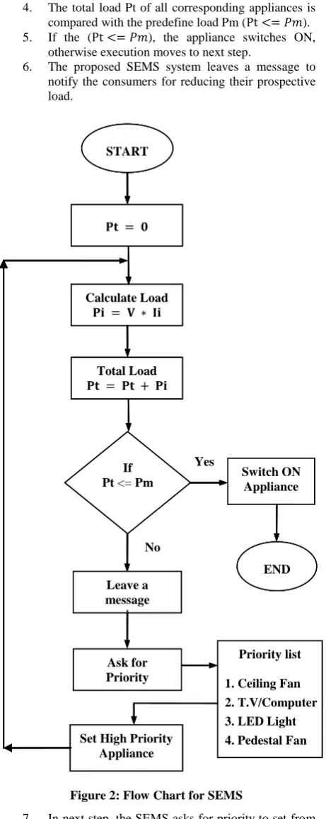
4.
SEMS ALGORITHM
The aim of proposed system is to reduce the electricity/power load of the consumer in between peak and off-peak hours. The consumer starts any appliance at any time. The proposed SEMS calculates the load of all appliances and allows continuing the electricity ON. The load is calculated by the formula for each appliance.
(1)
Where and .
The total load Pt is calculated by the sum of all appliances of load Pi.
(2)
(3)
(4) Followings are the steps for algorithm.
1. In start, the total load Pt is initialized with zero ( ).
2. Then the load Pi for the
i
th appliance is calculatedby the formula ( ).
3. In next step, the load of
i
th appliance is summed up4. The total load Pt of all corresponding appliances is compared with the predefine load Pm ( ). 5. If the ( ), the appliance switches ON,
otherwise execution moves to next step.
[image:4.595.56.287.72.651.2]6. The proposed SEMS system leaves a message to notify the consumers for reducing their prospective load.
Figure 2: Flow Chart for SEMS
7. In next step, the SEMS asks for priority to set from priority list.
8. The highest priority appliance is set according to their priority number.
9. After setting the priority of the appliance, again the whole procedure is repeated by calculating the appliance load Pi until the load is not balanced. The whole scenario of the proposed SEMS system is based on local Smart Grid Station that allocates a specific maximum load in watts for a consumer according to the nature of his use. This amount of maximum load is monitored by SEMS
system which disconnects the appliance, if consumer exceeds his allocated threshold limit. Each appliance is connected through wifi that is controlled wirelessly by SEMS. User specifies his priority from priority table/list. Highest priority of the appliance will be 1 and so on till end. There are some certain appliances/devices that are mostly used in homes. Each certain device consumes its certain load and voltage. According to that certain load and voltage the appliances/devices are restricted either switches ON or OFF.
Table 2. Appliances Power/Load
Sr. No
Appliance Name
Voltage Vi
Ampere Ii
Power/Load Pi=Vi*Ii
1 Fan 220 0.37 80
2 Light 220 0.135 30
3 Water Pump 220 0.477 105
4 Iron 220 5 1100
5 Refrigerator 220 3.64 800
6 TV/Computer 220 0.86 190
7 Air Conditioner
220 5.46 1200
8 Charger 220 0.135 30
9 Oven 220 4.55 1000
10 Pedestal Fan 220 0.45 100
11 Stereo 220 0.135 30
12 Juicer 220 0.205 45
5.
SMART METERING
The smart metering is being studied in many countries. A number of benefits are associated with smart meter even we focus it for electricity e.g. automated billing, real time electricity consumption, demand side load management and peak hours load balancing etc. it is a new technology that supports many smart functions according to the wish of consumers. There are also some certain hurdles to implement this modern technology like organizational, technical and as well as economical [17].
Smart meter is an intelligent meter installed on consumer side has following characteristics:
Controls real time use of electricity.
Provides a facility of meter readings (locally or remotely).
In special circumstances, electricity can be cut off remotely of the consumer.
Provides interconnection between network and devices for generation and distribution [17]. The intelligence in smart meter is being used to save energy. START
Calculate Load Pi = V * Ii
Total Load Pt = Pt + Pi
Pt = 0
If
Pt <= Pm Switch ON Appliance
END Leave a
message
Set High Priority Appliance
Yes
No
Ask for Priority
Priority list
1. Ceiling Fan 2. T.V/Computer 3. LED Light 4. Pedestal Fan START
Calculate Load Pi = V * Ii
Total Load Pt = Pt + Pi
Pt = 0
If
Pt <= Pm Switch ON Appliance
END Leave a
message
Set High Priority Appliance
Yes
No
Ask for Priority
Priority list
1. Ceiling Fan 2. T.V/Computer 3. LED Light 4. Pedestal Fan START
Calculate Load
Total Load
If
Pt <= Pm Switch ON Appliance
END Leave a
message
Set High Priority Appliance
Yes
No
Ask for Priority
Priority list
[image:4.595.316.544.180.518.2]There are three basic functions of a smart meter, measures electricity used/generated, remotely switches the consumer
and remotely controls the electricity consumption.
[image:5.595.56.543.91.433.2]
Figure 3: Smart Meter for Load Management
The smart meter acts as a modem/gateway using communication infrastructure like GSM/GPRS Power Line Carrier PLC or a permanent internet connection (DSL). In the proposed SEMS, an interface connects the smart meter with appliances and communicates with Controlling System Device CSD through wifi. Appliances are controlled directly and electricity consumption, electricity cost and consumed units reading can be displayed as results for future planning. Smart meter technology is a mature technology which is being implemented on large scale [17].
Figure 4: Before Smart Meter
A smart meter is a logical replacement of traditional mechanical meter like dial phone type writer with digital and
intelligent alternatives.
[image:5.595.304.542.456.662.2]A lot of advantages like low metering cost, reliability of supply and demand, variable pricing schemes, energy savings and easy detection of fraud are associated with smart meter.
Figure 5: After Smart Meter
The prediction about supply and demand of electricity also can be made. It can be installed on the origin of power generation to monitor and control the electricity while delivering to smart grid like virtual power plant concept. Many energy users, grid companies, metering companies, supplier and government take the benefits of smart metering by saving the electricity and maximizing their profit margins. Consumer reduces electricity cost by changing his behavior Hours
El
ec
tri
cit
y
Kw
Hours
El
ec
tri
cit
y
Kw
City Smart
Grid Station
Town Homes
H H H
H H
Appliance 1
Appliance 2
Appliance 3
Appliance 4
Appliance 5 Main
Switch
Home Smart
Meter
OS
Co
n
tr
o
ll
in
g
S
y
ste
m
De
v
ice
City Smart
Grid Station
Town Homes
H H H
H H
Appliance 1
Appliance 2
Appliance 3
Appliance 4
Appliance 5 Main
Switch
Home Smart
Meter
OS
Co
n
tr
o
ll
in
g
S
y
ste
m
De
v
[image:5.595.44.280.557.719.2]and also may receive a final bill monthly. The main challenge in smart metering is to replace the old traditional electricity
[image:6.595.57.551.95.389.2]mechanical meter with modern smart meter [17].
Figure 6: Before and After Smart Meter Comparison
After the installation of smart meter, the whole system of electricity must be upgraded due to large amount of data flow and process which can simplify the operations of metering companies. Grid and metering companies will receive accurate and actual data of electricity consumption in their areas. They can also monitor suspicious areas where the energy is stolen or the demand of electricity is extremely high than expected/ requirements. Thus, it is a tool to detect fraud and as well as a gate way in homes for consumers to provide new value added services [17].
The proposed SEMS controls the load management in peak and off peak hours. It calculates and compares the load of the consumer with the predefine threshold load ranges. If any consumer violates the predefined policy, the SEMS informs the consumer by using communication network wifi and a prior appliance is set to continue smartly. The consumer reduces his load by altering the appliances. This alteration is performed by maintaining a priority queue for appliances. The prior appliance is switched ON according to priority from priority queue. Again load is calculated and compared and finally the particular appliance is switched ON. The proposed system SEMS helps to prevent the theft of electricity, line loss and can generates real time bill on real time consumption of electricity and load management.
6.
CONCLUSION
Electricity consumption awareness is a basic step to save energy in homes and buildings. The modern technologies are being used for balancing demand side load management. We proposed an SEMS load management system for demand side load management that reschedules the consumer’s appliances according to their priority through wifi. Consumers can also be motivated to change their behavior for energy saving. The
proposed system distributes and balances the consumer load all over the day where they are connected smartly with Power Supply Company. Smart meter technology is developing and improving the safe, reliable and efficient response of demand side. The functions make it possible by setting the priority of the appliances to participate in load management that automatically reduces peak load.
The proposed SEMS controls the power consumption of appliances in abnormal conditions of overload or electric wire is burnt out. The system leaves an alert through wifi and sends signal to trip problematic appliance for the protection of consumer’s lives and safety of family.
7.
ACKNOWLEDGMENTS
Authors are thankful for worthy and helpful discussion and comments on the subject by honourable madam Eng. Sobia Arshad, Department of Computer Science, The University of Lahore, Sargodha Campus.
8.
REFERENCES
[1] Hashmi, M., Hänninen, S., and Mäki, K. 2011. Survey of Smart Grid Concepts, Architectures and Technological Demonstrations Worldwide.
[2] Budka, k., Jayant, D., John, H., Choi, J.I., Junhee, H., and Jinho, K. 2010. Smart Grid Research Focus: Economic Modeling, Networking, and Security & Privacy, Gachon Energy Research Institute, Kyungwon University, KOREA.
[3] Louie, H., Burns M., and Lima, C. 2010. An Introduction and User’s Guide to the IEEE Smart Grid Web Portal.
Ele
ct
ri
ci
ty K
w
[4] Ruihua, Z., Yumei, D., Yuhong, L. 2010. New Challenges to Power System Planning and Operation of Smart Grid Development in China.
[5] Bao-shu, L., Wan-kun, C., Yu-min, G. 2012. Release System of Real-Time-Price Oriented to Smart Meters. [6] Wang, P., Huang, J. Y., Ding, Y., and Goel, L. 2010.
Demand Side Load Management of Smart Grids Using Intelligent Trading/Metering/ Billing System. Nanyang Technological University, Singapore.
[7] Kang, M. S., and Sheng, J. 2011. Implementation of Smart Loading Monitoring and Control System with ZigBee Wireless Network.
[8] Shamsi, P. and Fahimi, B. 2011. Remote Control of Smart Appliances Using MPEI, Spain.
[9] Dissanayaka, D.M.L.B., Fernando C.T.J., and Abeyratne S.G. 2011. Smart Meter Based Inverter Controlling Network for Demand Response Applications in Smart Grids. ICIIS, Sri Lanka.
[10] Tang, G. Q. 2011. Smart Grid Management & Visualization Smart Power Management System, Canada.
[11] Lu, X., Lu, Z., Wang, W. and Ma, J. 2011. On Network Performance Evaluation toward the Smart Grid: A Case Study of DNP3 over TCP/IP.
[12] Lowe, D. 2012. How to Use Relays to Control Electronic Line-Voltage Circuits, http://www.dummies.com/how-to/content/how-to-use-relays-to-control-electronic-linevoltag.html.
[13] http://www.allaboutcircuits.com/vol_4/chpt_5/4.html, 2014. Protective Relays.
[14] Mitra, S. 2011.”Wireless sensor network”, Calcutta Institute of Engineering and Management, India. [15] Thusiast, W. S. N. 2008. “Wireless Sensor Network
Devices”,
http://wirelessm2m.blogspot.in/2008/01/wireless-sensor-network-devices.html.
[16] http://www.sensornets.csiro.au/content/equipment/fleck-nano. Fleck Nano.
[17] Gerwen, R.V., Jaarsma, S., and Wilhite, R. 2006,”Smart Metering”, KEMA, The Netherlands.
[18] Mahmood, A., Ullah, M. N., Razzaq, S., Naeem, M., Javaid, N. 2014. “A New Scheme for Demand Side Management in Future Smart Grid Networks”, Procedia Computer Science, vol. 32, pp. 477-484.
[19] Papageorgas, P., Piromalis, D., Iliopoulou, T., Agavanakis, K., Barbarosou, M. Prekas, K., Antonakoglou, K. 2014. Wireless Sensor Networking architecture of Polytropon: “An open source scalable platform for the smart grid”, Energy Procedia, vol. 50. [20] Kim, W.H., Lee, S., Hwang, J. 2011.”Real-time Energy
Monitring and Controlling System based on Zigbee Sensor Networks”, Procedia Computer Science, vol. 5, pp 222-225.

![Table 1. ANSI Protective Relay Designation Numbers [13]](https://thumb-us.123doks.com/thumbv2/123dok_us/8029545.768321/3.595.51.283.491.739/table-ansi-protective-relay-designation-numbers.webp)