Centrifugal ironmaking.
ROBSON, Alan Lawson.
Available from Sheffield Hallam University Research Archive (SHURA) at:
http://shura.shu.ac.uk/20285/
This document is the author deposited version. You are advised to consult the
publisher's version if you wish to cite from it.
Published version
ROBSON, Alan Lawson. (1982). Centrifugal ironmaking. Doctoral, Sheffield Hallam
University (United Kingdom)..
Copyright and re-use policy
Sheffield City Polytechnic Library
ProQuest Number: 10700930
All rights reserved
INFORMATION TO ALL USERS
The quality of this reproduction is dependent upon the quality of the copy submitted.
In the unlikely event that the author did not send a com plete manuscript and there are missing pages, these will be noted. Also, if material had to be removed,
a note will indicate the deletion.
uest
ProQuest 10700930
Published by ProQuest LLC(2017). Copyright of the Dissertation is held by the Author.
All rights reserved.
This work is protected against unauthorized copying under Title 17, United States C ode Microform Edition © ProQuest LLC.
ProQuest LLC.
789 East Eisenhower Parkway P.O. Box 1346
C E N T R I F U G A L I R O N M A K I N G
A THESIS
Submitted to the Council of National Academic Awards for the Degree of
DOCTOR OF PHILOSOPHY
by
ALAN LAWSON ROBSON
For Work Carried Out at
Teesside Laboratories British Steel Corporation
Department of Metallurgy
CONTENTS Page No.
ACKNOWLEDGEMENTS
ABSTRACT
NATURE OF THE INVESTIGATION
SYMBOLS USED IN THE TEXT
1 INTRODUCTION 1
2 LITERATURE SURVEY 4
2.1 Reduction of Iron Oxide Bearing 4
Slags by Solid Carbon
2 . 2 Mass Transfer Studies 7
2.3 Smelting Reduction 9
3 CENTRIFUGAL IRONMAKING PROCESS (C.I.P.) l4
3.1 Smelting Reduction l4
3.1.1 Concept 15
4 MATHEMATICAL MODEL 22
4.1 Description of the Model 22
4.1.1 Heat Transfer 24
4.1.2 Carbon Transfer 25
4.1.3 Oxygen Transfer 27
4.1.4 Iron Transfer 28
4.1.5 Coal and Limestone Decomposition 28
4.2 Mode of Operation 29
5 LABORATORY EXPERIMENTS 32
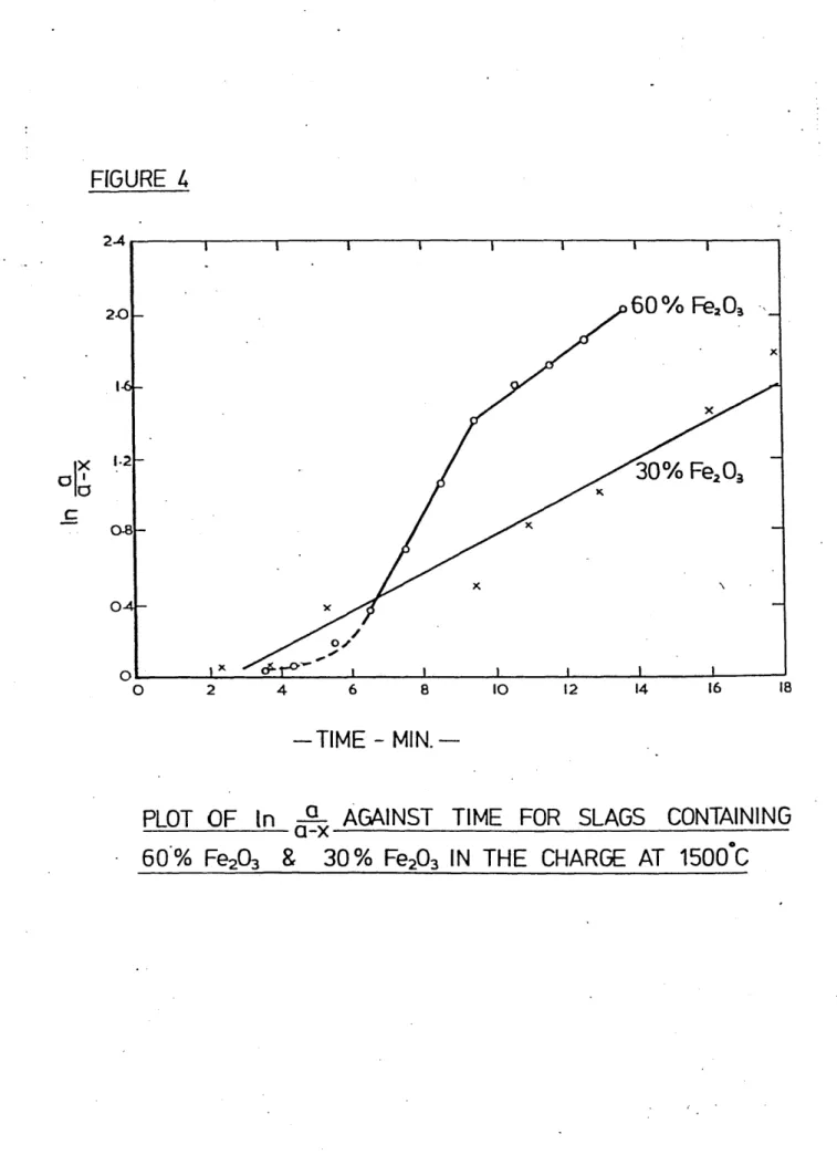
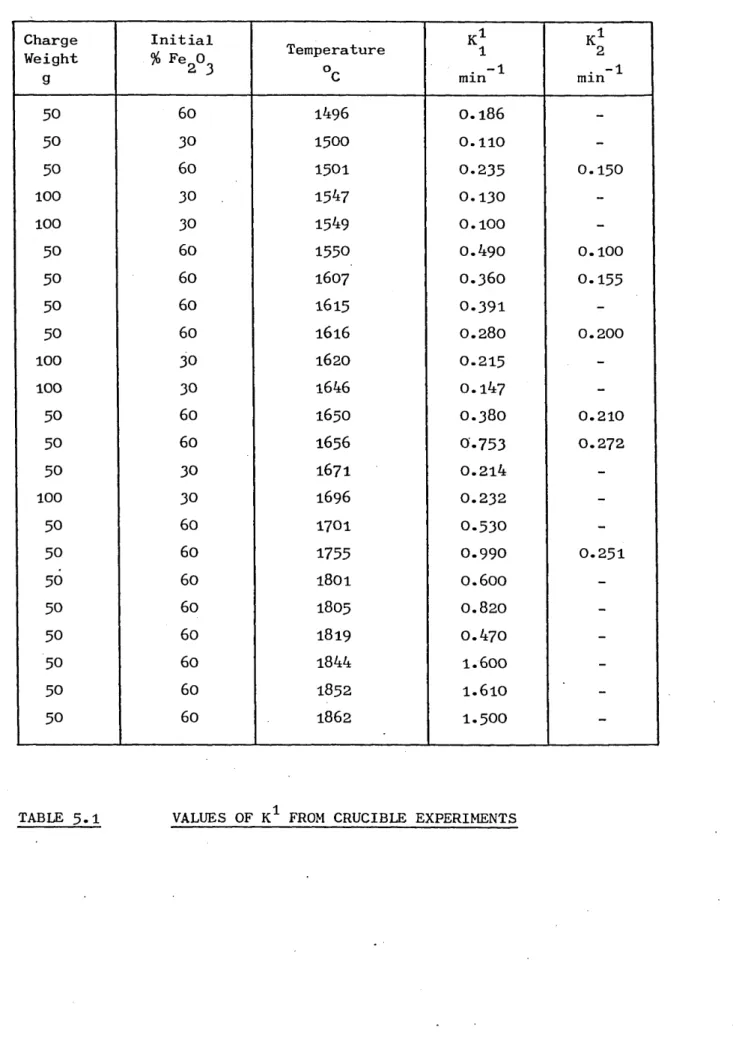
5.1 Kinetics of the Reduction of Molten 32
Iron Containing Slags by Solid Carbon
5.1.1 Reaction Kinetics 32
5-1-2 High Temperature Reduction Apparatus 34
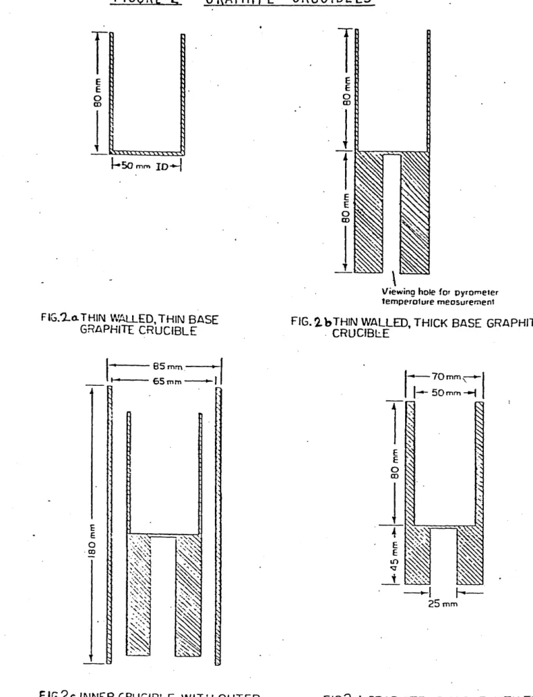
5-1-2 . 1 Crucible Material and Construction 36
5-1-3 Reduction of Iron Oxide Containing 37
CONTENTS cont? d Page No.
5-1.4 Experimental Results 40
5-2 Heat and Mass Transfer Model Studies 46
5-2.1 Heat and Mass Transfer Analogue Theory 46
5-2.2 Experimental Determination of Naph- 48
thalene Evaporation Rates
5.2.2.1 Description of the Model 48
5.2.2.2 Naphthalene Sublimation Experiments 49
5-2.2.3 Naphthalene Sublimation Experimental 51
Results
5.2.3 Results and Discussion of Heat and 52
Mass Transfer Model Studies
6 PILOT PLANT INVESTIGATIONS 60
6 . 1 Description of the Pilot Plant 60
6.1 . 1 Initial Design 60
6.1 .2 Modifications to the Pilot Plant 66
6 . 2 Raw Materials 69
6 . 3 Operational Procedure for the Pilot 69
Plant
6.3*1 Start-up Procedure 70
6.3-2 Batch Operating Procedure 70
6.3-3 Introduction to Continuous Operation 72
6.3-4 Continuous Operating Procedure 74
6-3-5 Surge Casting 7 5
6.3 . 6 Rod Casting 76
6.3-7 Pilot Plant Measurements 77
6.3-8 Bed Sampling 79
6.3-9 Determination of Process Yield from 8l
Plant Experiments
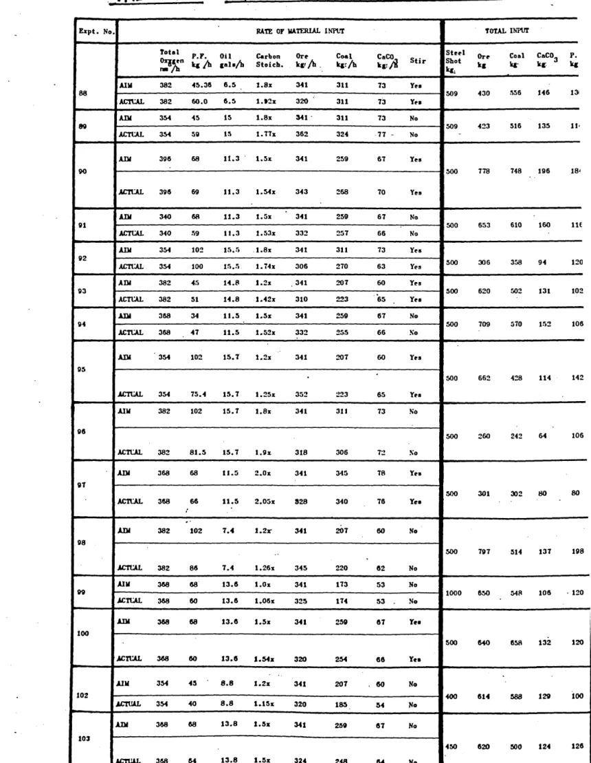
6.4 Batch Experiments 83
6 . 5 Results of the Batch Experiments 86
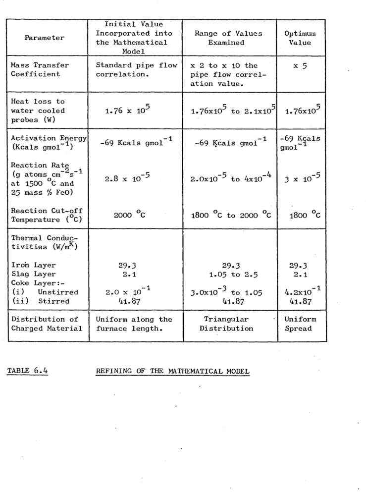
6 . 6 Analysis of the Batch Results 109
6.6 . 1 Technique for Refining the Mathematical 109
Model
6.6 . 2 Mass Transfer Coefficient Values 112
CONTENTS cont'd Page No.
6.6.4 Reaction Kinetics ll4
6.6 . 5 Thermal Conductivity of the Coke Bed 117
6.6 . 6 Feeding Distribution of Solids 119
6.6 . 7 Testing of the Improved Mathematical 120
Model
6 . 7 Conditions for the Continuous 132
Experiments
6 . 8 The Results of the Continuous 133
Experiments
6.8.1 Experiment No. Il8 135
6.8.2 Experiment No. 119 l4l
6.8 . 3 Experiment No. 122 l46
DISCUSSION 151
7-1 Scope of the Thesis 1 51
7-2 The Mechanism of the Carbon Reduction 1 51
of Iron Bearing Slags
7-3 Convective Heat and Mass Transfer in 165
the Reactor
7.4 The Use of Factorial Experiments to 169
Improve the Mathematical Model
7.5 The Planning of the Continuous 173
Experiments
7 . 6 The C.I.P. Process 176
7.6 . 1 Performance in the Continuous 176
Experiments
7.6.1(a) Ancillary Engineering Equipment 176
7.6.1(b) The Design of the Reactor 178
7.6.1(c) Performance in the C.I.P. Process l80
7.6 . 2 Guidelines for Operating Practice 182
Established in this Work
7.6 . 3 Future Development Work l84
7.6.4 Scale-up. Problems for Commercial 188
Operation
CONCLUSIONS 191
CONTENTS cont'd Page No.
APPENDIX 1
APPENDIX 2
APPENDIX 3 APPENDIX 4
APPENDIX 5
APPENDIX 6
Heat Transfer by Radiation from the Gas Core to the Bed
Pulverised Fuel Combustion
Oxidation of the Slag Layer
Metal Oxidation
Analysis of Raw Materials Used During C.I.P. Experiments Photographs Taken During the Factorial Experiments
202
203
206
208
210
ACKNOWLEDGEMENTS
The author was a part-time student of Sheffield Polytechnic during the
period of this work and he wishes to extend his thanks to the staff of the Department of Metallurgy, and in particular to Dr. A.W.D. Hills for his valuable supervision.
The work was carried out at the Teesside Laboratories of the British
Steel Corporation, and the author wishes to express his thanks to the
management of the laboratories for providing the facilities. Much gratitude is owed to Mr. D.A. Hawkes for his enthusiastic support and
constant encouragement, particularly during the earlier part of the
work, and to Dr. M.W. Davies for his continued support and guidance.
The help and encouragement of colleagues is recalled with pleasure, particular thanks are owing to Mr. R.H. Carter, Mr. C.J. Treadgold,
Mr. A. Marples and Mr. A. Uemlianin (pilot plant team), to Mr. K.G. Bain
who assisted with the high temperature reduction studies, and to Dr. R.J. Hawkins for many stimulating discussions.
ABSTRACT
A process for producing liquid iron from iron ore is being developed
on the pilot plant scale that avoids the use of high grade metallurgical
coal and the agglomeration of iron ore concentrates. The use of a
centrifuge furnace provides the maximum surface area for reaction between layers of molten iron oxide and solid carbon. The iron product is
centrifuged to the walls of the reactor where it provides a protective
barrier between the highly corrosive liquid slag and the refractory walls. Carbon monoxide, released from the reduction reaction, combusts
with oxygen in the central gas core and the heat produced is radiated back to the reacting species.
To help understand the interaction of the various physical and chemical
reactions occurring inside the reactor, a mathematical model had been written describing the process. Laboratory scale studies were carried
out to examine and test the validity of some of the assumptions used
in the model, and where necessary modify these assumptions. Two such investigations were the reaction between solid carbon and liquid iron
bearing slags at temperatures up to 2 135 K, and the determination of
heat and mass transfer coefficients from the central gas core to the
rotating bed using a naphthalene sublimation technique.
To widen the basis on which the predictions from the model could be
compared with actual pilot plant operating data, a series of experiments were carried out on the plant covering a broad range of input conditions.
These experiments were carried out in the batch mode i.e. the raw
materials were charged into the furnace until its capacity was reached, after which the entire contents were discharged, analysed, and compared
campaign was then carried out to determine more realistic values for
the parameters used in the model. Sufficient information was obtained from this study to provide the optimum conditions for attempting con
tinuous ironmaking operations on the pilot plant.
Three continuous ironmaking experiments were carried out, with the
maximum length of continuous operation in any one experiment being of
ten hours duration. Improvements in operation and measurement tech niques enabled process data to be collected at regular intervals which
allowed the process efficiency to be determined on a continuous basis.
The iron ore input rate was held constant at kg/h and high conversion
NATURE OF THE INVESTIGATION
The principal purpose of the investigation reported in this thesis was to gain sufficient understanding of the phenomena occurring in the
Centrifugal Ironmaking Process to allow the process to be operated
consistently with high efficiency. To do this, a pilot plant reactor was operated and modified under the direct direction of the author.
In addition, experience and observation of this reactor was augmented
by the predictions of a complex mathematical model of the process. The author did not develop this model, although he was involved in a
number of modifications to the formalisms used and he contributed to
the programme of laboratory experiments which provided values for some of the critical parameters used in the model.
Once the model had been developed and validated in a programme of comparisons, directed by the author, with the performance of the pilot plant, it was used, together with the pilot plant, to explore various
operating conditions and hence to show those operating conditions which would result in the most efficient operation. This work, both for the
model and the pilot plant, was planned and directed by the author.
The pilot plant had been built prior to the start of the investigations that are the subject of the thesis, and some initial experience of its
operation had been obtained. The initial sections of the thesis thus
describe the plant, and this initial experience, together with the mathematical model, and the output that it could provide.
The results and the theories developed are, to the best of the author's
knowledge, original except where reference has been made to other
SYMBOLS USED IN THE TEXT
A Area
A n Area of nozzle
a Weight of iron oxide at zero time
a , a Constantsl ’ 2
C Molar concentration
C o Initial molar concentration
Csi Molar concentration m the slag
C Specific heat
P
D^ Diffusion coefficient of species i
D 1T^ AB Diffusion coefficient of species A in a mixture of A and B
d Diameter
E Activation energy
f Shape factor
G Burner thrust
h Heat transfer coefficient
h^ Mass transfer coefficient
J H Dimensionless factor for heat transfer
Jp Dimensionless factor for mass transfer
K Equilibrium reaction constant
P
K s Surface reaction rate coefficient
1
k, k Rate constants
k o Rate constant at initial concentration
k^ Mass transfer coefficient of species i
k Absorption coefficient
1 Characteristic length
MN Molecular weight of air
Mn Mass flow rate through the nozzle
m Mass concentration
mo Initial mass concentration
N Number of moIs
•1 1
n.i Molar flux of a species i
n Exponent
P.i Partial pressure of species i in the bulk gas
Pe Partial pressure at the exit
^p.f
.
Rate of carbon removal per unit external geometric surface area•1 1 Heat transferred by radiation
R Gas constant
r Radius of particle
ro Base reaction rate
rT • Reaction rate at temperature T
T Temperature
T.l Temperature at inlet
tb Temperature of bed
T
g Temperature of gas
t Time
u Mass velocity
u • Velocity
V Volume
W Weight loss
X.1 Partial pressure of species i at the interface
co
°x
° Partial pressure of CO in equilibrium at the carbon surface
Partial pressure of CO in equilibrium at the slag surface
Concentration of FeO in the slag bulk Amount reacted after time t
Distance from centre of particle
Mass transfer coefficient dependent on stirring intensity
Thickness of gas film Pressure differential
Emissivity of bed
Emissivity of gas Temperature
Density
Stefan-Boltzmann constant
Viscosity
Angular velocity
Pseudo-equilibrium constants
Nusselt number
Prandtl number
Reynolds number for pipe flow Rotational Reynolds number
1 INTRODUCTION
Centrifugal Ironmaking is the name given to a technique in which
liquid iron ore and coal are reacted together at high temperatures,
resulting in a liquid iron product- The reaction takes place in a
cylindrical vessel rotating at a speed high enough to hold the dense
liquid iron against the refractory walls, thus protecting them from attack by the molten iron bearing slag and coal which float on top
of the iron.
The principal reasons favouring the Centrifugal Ironmaking process
are that low grade coals can be used as the reductant and there is no
need for charge preparation- Thus, unlike the blast furnace, this process is independent of coking coal supply and it does not require
sinter plants, high temperature stoves, high pressure equipment and coke ovens, so that considerable capital cost savings are possible.
Further, the centrifuge technique allows very high temperatures to be generated within the furnace without damage to the refractories, which
are protected by the layers of liquid held against the walls. The basic concepts of the Centrifugal Ironmaking process are given in more
detail in section
To allow a thorough investigation of ironmaking using this technique, a pilot plant was built at the Teesside Laboratories of the British
Steel Corporation. A description of this pilot plant is given in
section 6.1. Some initial operating experience of this pilot plant had
been obtained before the start of the work described in this thesis. The majority of the earlier experiments investigated the problems of
containing liquid metal and slag within a centrifuge, and the engineer
period was protracted by a hot metal breakout which delayed the
experimental programme for nearly a year. During this early period
it was found that strongly oxidising conditions in the gas core
(5 : 1, CO to CO ratio) would lead to oxidation of the metal bed and
very high bed temperatures. This factor was considered to be the main
cause of the "break out" referred to above. Following this commission ing period a series of batch experiments were carried out, i.e.
charging the furnace with ore, coal and limestone to less than its capacity, then completely discharging the furnace contents by reducing
the drum speed to zero. These experiments usually lasted about two
hours. The average iron ore feed rate being 200 kg/h, with coal input
rates equivalent to up to 3 x the stoichiometric carbon requirement
for iron and carbon monoxide production. It was also found necessary
to spread the iron ore, coal mixture over a large proportion of the
furnace area to prevent local freezing at the feed end of the furnace. The injection of fine coal into the gas stream to enhance heat transfer
to the reacting bed was found necessary, also the oxygen input rate was
adjusted to generate a CO : CO ratio of around 2 : 1 inside the furnace. Conversion efficiencies of iron ore to iron of greater than
90% were obtained from a number of experiments. Encouraged by the
success of these early batch experiments, the experimental programme
was then directed towards a reduction of the coal rate to around 2 x
the carbon stoichiometric requirements, increasing the iron ore ihput
rate to around 350 kg/h, and attempting continuous tapping from the
furnace for a period of up to six hours. A number of different cast
A large proportion of time, 1^ years, was spent on this programme of
work, with only limited success. Continuous tapping was never achieved
and the conversion efficiencies of iron ore to iron were low, usually between 0 and 50%- The problem of chemical attack of the refractories
in the cast end dam became acute during the longer, continuous operation
experiments and resulted in several premature terminations of experiments. The concept of mixing the reacting species by mechanical means, i.e.
cycling the drum speed between an upper and lower set speed, was
introduced during this operating period. Another major problem
encountered when moving from the batch to the continuous experiments was
that during the course of the experiment it was difficult to maintain
steady input rates of the ingoing materials. Observations showed that,
on occasions, even small changes in input conditions had serious
repercussions on process performance and could result in a fully oxidised bed, or severe freezing of the bed. Thus a relatively narrow operating band had to be followed in order to achieve successful operation. Thus
the operating flexibility of the process was not known at this time, and it was the result of this comparative lack of success that encouraged
the development of the mathematical model of the process and the work
2 LITERATURE SURVEY
2 . 1 Reduction of Iron Oxide Bearing Slags by Solid Carbon
The difficulties in carrying out laboratory scale experiments with molten slags at elevated temperatures has meant that surprisingly few investigations have been reported. The problems of containing the liquid
slags and conducting these experiments under closely controlled conditions
to make the results meaningful have all added to the experimental problems,
plus the difficulty in interpreting experimental data from a reaction zone involving the interaction of four phases, i.e. liquid iron oxide,
solid carbon, liquid iron and product gas. However, a number of invest
igations have been reported at lower temperatures.
1
Philbrook and Kirkbnde studied the reduction of molten slags containing
up to 5% FeO from a ternary lime-alumina-silica mixture with carbon
saturated iron in a graphite crucible, and with the graphite crucible only, at temperatures between 1 430 °C and 1 570 °C. The overall
reaction was found to be 2nd order, with the slag-carbon saturated iron
reaction being faster than the slag-carbon reaction. The value of the
reaction rate constant between slag and graphite was determined as
1 . 2 x 10 ^ g FeO/min cm2 . (% FeO)2.
It was not possible to deduce a reaction mechanism to interpret the results alone, however several alternative reaction mechanisms were
postulated. These were in terms of intermediate reaction products, dissociation of FeO within the slag, nucleation of gas or metal, and
surface phenomena leading to reaction through iron films on rising 2 bubbles of carbon monoxide in the slag. Tarby and Philbrook also
studied the reduction of up to 5% FeO from both a ternary
by carbon saturated iron in graphite crucibles, at temperatures between
1 550 °C and 1 575 °C. The reaction rate constants and orders of
reaction were derived by an integration and a differential method.
Using the latter method two distinct periods of reaction were identified.
The first period, which was the more rapid, was stated to be caused by
vigorous evolution of carbon monoxide gas resulting in forced convection within the slag. The second, and slower rate of reduction, takes over
as the boiling action subsides within the system and the flow conditions
within the slag become those defined by natural convection. For the slag-graphite system, they found that for the initial period an order
of reaction between 1 . 1 and 2 . 0 was derived, and for the following stage a first order of reaction. The measured rate constants varied with slag
composition and their differences might result from the activity of 'FeO'
in the various slags.
3
Kramer, Beer and Brandi using graphite and coke crucibles with a
thermogravimetric balance studied the reduction of slags containing up
to 70% iron oxide in the temperature range 1 300 to 1 500 °C. They found that reduction of iron oxide in CaO-SiO^ slags occurred several times
more quickly than in binary FeO-SiO slags, but no difference in reaction rates was detected between the coke or graphite crucibles. The activation
energy for the reaction was found to vary between 20 and 40 kcal/mol for
the range of slags studied. They concluded that the reduction reaction
proceeds via two consecutive steps
FeO + CO = Fe + CO ... (2.l)
CO + C . = 2C0 (2.2)
Kondakov, Rhzhonkov and Golenko reduced liquid iron oxide in a
graphite crucible in the temperature range 1 450 °C to 1 650 °C.
From their observations, the gasification of carbon, reaction 2.2,
was found to be the rate limiting step.
1
Yershov and Popova^ studied the reaction between a spinning carbon disc and molten FeO - CaO - SiO slags held in a zirconia crucible at
1 600 °C in which the disc was immersed. The rate of reaction was
determined by measuring the loss in weight of the carbon disc over a
specified time with a given contact surface area between the carbon and the slag. At high FeO levels, between 40 and 60%, the rate of
reaction was found to be independant of the rate of rotation of the
carbon disc and the rate determining step was deduced to be by inter facial chemical kinetics. At lower FeO levels of 10 - 20%, the rate
of reaction increased with increasing rotational speed of the carbon disc, and the rate limiting step was said to be the diffusion of
oxygen in the slag. An increase in CaO content in the slag for a given FeO level resulted in an increase in reaction rate.
6
Sugata, Sugiyama and Kondo used rotating carbon or coke rods reacting
in a range of slag compositions with FeO levels between 5 an(i 90%. The
reaction was carried out in pure iron crucibles which limited the temperature range studied to between 1 350 °C and 1 450 °C. At high
rotation speeds the rate of reaction was determined by the interfacial
chemical reaction FeO + C = Fe + CO. At lower rotation speeds the reaction rate was considered to be controlled by both diffusion within
The importance of the gas evolution step was underlined by the work of 7
Shavrm et al who used an X-ray technique to observe the evolution of
gas bubbles from a graphite sphere immersed in an iron oxide-lime-boric
oxide slag. They found that the shape and size of the gas bubble
depended upon the properties of the melt and the surface of the carbon. They also found two regimes for the detachment of bubbles from the
carbon surface, namely single bubble and multi bubble boiling, and which
regime they operated in depended on the iron oxide concentration of the melt and the temperature of reaction.
X-ray studies of the interaction between liquid iron-carbon droplets and
8
iron oxide bearing slags have been reported by Davies et al , which
underlined the importance of surface properties on the nucleation and
growth mechanism of CO bubbles. In the same paper, experiments
involving the reaction of FeO - CaO - SiO slags in graphite and coalu
crucibles between 1 400 and 1 500 °C were reported. No difference in the reaction rate was found when using either a graphite or a coal crucible.
They concluded that the most likely mechanism controlling the reaction
in their particular experimental arrangement was mass transfer in the slag phase.
2 . 2 Mass Transfer Model Studies
The use of isothermal scale models to study flow patterns and mass
transfer coefficients in complex industrial plant has been widely used 9
for some time now. Gray et al described some of the equipment and
methods employed in the solution of industrial fluid flow problems by model techniques, using air as the operating medium. Several typical
of the models used, and the flow distribution in pipes and furnaces.
10
Bacon also describes techniques in which water, as well as air, has
been used as the flow medium. Techniques were described, using water
as the flow medium, in which good flow visualisation was achieved inside
furnace models, however for quantitative work, air should be used as the
flow medium. Equality of Reynolds Number in the model and furnace was
taken as the main criterion of similarity, as well as geometric similarity. Bacon described a technique for scaling down the burner nozzle used in oil-fired furnaces. This was necessary because the
momentum of the fuel entering the furnace was the greatest single
factor affecting the flow pattern in the furnace chamber. Thring and 11
Newby developed a criterion to account for the non-isothermal mixing
of the burner flame. Their criterion essentially depended on the measure of two parameters to ensure mixing similarity, i.e. a recircu
lation parameter 0 which relates the input flows and the furnacer
dimensions to the degree of recirculation, and an equivalent burner size
to account for the temperature effects of the flame. The Thring-Newby criterion is strictly only applicable to systems with a small nozzle
diameter in a large mixing chamber and to overcome these difficulties 12 a modification to the Thring-Newby criteria was proposed by Robertson in which the equivalent burner diameter was replaced by an equivalent
mixing length.
Several different techniques have been used for measuring mass transfer
• • 13
coefficients under different geometric arrangements. Davies et al l^t
and Galsworthy , describe a solid sublimation technique using
cylindrical billets. Mass transfer coefficients were derived from the
weight lost by sublimation of naphthalene when air was blown through
the models, in which the naphthalene coatings represented the heat transfer surfaces of the furnaces. Heat transfer coefficients were
derived from mass transfer measurements using the Chilton-Colburn
15 l6
analogy between heat and mass transfer. Lucas et al describe an electrolytic mass transfer technique using the reduction of the
ferro-cyanide ion at a nickel electrode in an alkaline potassium
ferri-ferrocyanide solution. The application of this method to a furnace model involves operating the model as an electrolytic cell.
17
Harvey et al carried out experiments to determine the pressure drops
and flow patterns for fluids flowing through a tube rotating about its
own axis. They found that the effect of increasing the rotation of the
tube was to increase the friction factor at Reynolds Number less than
3 000 and for Reynolds Number greater than 3 000 to decrease the
friction factor with increasing tube rotation. At a Reynolds Number of
3 000 the friction factor had a single value irrespective of the
rotational speed of the tube. However, with a Reynolds Number of 8 000
and a rotational speed of 3 000 rpm the friction factor was reduced by
50%. Rotational speeds in excess of 750 rpm also tended to suppress turbulence and extended the laminar flow region to high Reynolds Number.
2.3 Smelting Reduction
The production of iron from liquid iron ore in smelting reduction processes is usually carried out with solid carbon, charged as either
coke or as coal, but the use of oil or hydrocarbons is also possible.
The major problems to overcome in any smelting reduction process is to
reaction- This usually means the use of oxygen to obtain high gas temperatures, without reoxidising the iron produced, and the preven
tion of severe refractory attack by the highly aggressive iron oxide
bearing slags inherent in any smelting reduction process.
The majority of smelting reduction processes have only been developed
as far as the pilot plant stage and each process has attempted
different variations in design or practice to overcome the problems of
heat transfer and slag attack. For instance, the Eketorp-Vallak
l8
process used a refractory lined container to hold the iron, slag and
coke layers. Oxygen was injected into the gas phase to produce high temperatures for heat transfer to the molten bath. The iron ore was
charged into the bath in the form of a curtain around the sides of the vessel, thus protecting the refractory from the high gas temperatures.
The problem of slag attack of the refractory still remained.
The use of rotating furnaces in the iron and steel industry is well
19 20
established, for example the S.L.R.N. and Kaldo processes • The 21
DORED process was similar to the Kaldo process in that an inclined cylindrical vessel was rotated to promote mixing of the reactants.
Oxygen was added through the open mouth of the vessel into the central
gas core. Iron ore, coke breeze and limestone were charged into the furnace to produce layers of iron, iron oxide bearing slag and coke.
The combustion of the carbon monoxide to carbon dioxide inside the
rotating furnace heated the refractory walls of the vessel. The
rotation of the furnace was such that it carried the liquid bed up the
sides of the vessel, after which, the liquid bed would rain down through the hot gas core and mix with the coke layer floating on the liquid bed
liquid bed and intimate mixing of the coke and iron oxide slag would
occur. This process worked with a high degree of chemical efficiency
but the continual exposure of the refractory surface to slag rich in
iron ore meant that refractory consumption was excessive and the
process was uneconomic to operate on a commercial basis.
A rotary furnace was again used in the Rotovert Smelting Reduction 22
process developed on the pilot plant scale at M.R.P. , Lulea in Sweden. A 6 tonne converter was used with an inner diameter of 1 m,
which rotated around its vertical axis, giving a liquid metal parabola
1 m high at a rotational velocity of 85 rpm. The refractory used was
tar bonded dolomite, although magnesite and chrome magnesite were also used. The liquid metal parabola formed inside the converter was to
protect the refractory from slag attack. The raw materials of iron ore, coke and limestone were fed onto the metal parabola. Two types of
material feeding systems were tried. A stationary, continuous feeding probe, axially mounted was first used but the distribution of the charge
on the parabola was poor. A movable, continuous feeding system was
developed which distributed the charge over the main part of the parabolic surface. A combustion system was also developed from a
simple 6 holed oxygen nozzle, axially mounted, to one with a central
oxy-oil burner, plus a 17 hole oxygen lance as a secondary combustion
system. Iron ore (magnetite) feed rates of up to 1000 kg/h have been
tried with a maximum input of 750 kg during an experiment. The coke input was of the order of 1 tonne/tonne metal produced, which gave a coke layer thickness of up to 10 cm at the beginning of the experiment.
were encountered and measurements indicated that only 2 0% of the total heat available was transferred to the liquid bed, which was insufficient
to compensate for the heat requirements within the bed and heat losses from the plant. Refractory wear in the upper part of the converter was
also a problem and this produced an increase in the slag basicity which
made the slag viscous and unmanageable.
A development from the Rotovert process was carried out at C.S.M., Rome,
23
Italy, called Rotored , again on the pilot plant scale. The Rotored process, like Rotovert, spins in the vertical axis, however the base of
the converter was open, compared with the closed bottom of the Rotovert process. On the pilot plant scale the Rotored furnace had an internal
2
surface area available for reaction of 1 . 5 2 m and spun at 85 rpm.
The concept of the process was to feed solid coke to form a layer on the
inner walls of the furnace of sufficient depth to prevent any contact
between the walls and the iron ore. The raw materials charged were an iron ore mix (mainly Venezuelan ores), coal and limestone with Liquid
Petroleum Gas and oxygen added in the centre of the rotating furnace.
The raw materials could be fed either as separate layers or as a mixture
through a feeder probe which traversed up and down the length of the
furnace. The proposed feeding technique, when feeding separate materials,
was to provide alternate and separate layers of a non-uniform thickness
along the reactor wall. The thickness of the ore layer was to decrease
uniformly from a maximum, corresponding to the mouth of the reactor, to
.zero at the lower part of the cylinder. The thickness of the coke layer would be the reverse of the ore layer. It was proposed therefore to use
layer. The process has only operated in the batch mode and the standard
operating procedure was to have a feeding and heating period ( ^ 7 0 min
duration) followed, by a heating and solid state reduction period (« » 8 0 min
duration), followed by a further feeding and heating period, and so on.
The final period (of^35 min duration) was for liquid state reduction only. Attempts to operate this process on a continuous basis have proved
3 CENTRIFUGAL IRQNMAKING PROCESS (C.I.P.)
3-1 Smelting Reduction
The principal chemical reaction (overall) which accounts for the
reduction of iron ore (assumed to be -*-n smelting reduction
processes
is:-Fe 0 + 2 3 3 C = 2 Fe + 3 CO (3.1)
For each tonne of iron produced, 1.430 tonnes of Fe 0 and O2 3 .3 2 3
tonnes of carbon are required. In addition to the iron produced the 3
reaction also yields 602 m of carbon monoxide gas. The reaction is highly endothermic and heat is required to sustain the reaction in
addition to the heating requirements of the reactants.
24
The heating requirements to enable the reaction to proceed, at say 1600 °C, are as
follows:-Heating and fusion of the ore = 2 . 7 7 GJ/tonne Fe
Heating of the carbon (coal) = O.89 GJ/tonne Fe
Heat required for the reduction reaction = 3-^7 GJ/tonne Fe
7.73 GJ/tonne Fe
It is possible to provide this heat by burning the carbon monoxide gas released from the reduction reaction
CO + i 0 = CO 2 2 (3.2)
This reaction required 300 O^/tonne Fe to burn the carbon monoxide
other thermal demands of the process are taken into account, e.g.
heat losses through furnace walls, through water cooled probes and
the dissociation of the limestone etc., it becomes obvious that the
thermal demands of the process can only be met by burning additional fuel, say oil or coal.
The product gas from these combustion reactions is carbon dioxide
which is oxidising towards iron. Moreover, it is necessary to maintain
strongly oxidising conditions in the gas core to burn the CO and other
fuels sufficiently rapidly to liberate enough heat to sustain the
reduction reaction. It is also necessary, of course, to maintain reducing conditions at the iron ore - carbon reaction interface. It
is clear that an understanding of the competing oxidation and reduction reactions occurring within the furnace and the net transfer of heat and
the gaseous species from the central gas core to the reacting bed
requires a description of the processes occurring inside the furnace to be developed. For this purpose a mathematical model describing the
key areas in the Centrifugal Ironmaking process was developed.
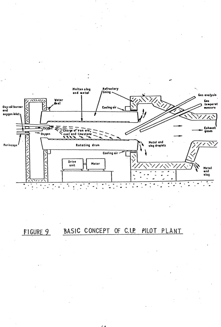
3-1-1 Concept
A cylindrical furnace is rotated about its horizontal axis at a
rotational speed such that the constituents of the furnace, (liquid
iron, liquid slag, solid carbon), are spread around the inner surface of the furnace in a uniform film. The relative densities of the
constituents ensures that the constituents segregate into discrete
layers. The heaviest constituent, iron, is maintained as the outer
and carbon can then take place in the inner, higher temperature layer.
Carbon monoxide gas is evolved from this reaction which enters the
gas phase in the central region of the furnace. Oxygen is then added
to the furnace which combusts the carbon monoxide to carbon dioxide,
thus supplying the heat necessary to sustain the endothermic reduction reaction of the iron oxide by carbon. Whilst the furnace is spinning
iron ore and coal are charged. Limestone is also added to flux the slag resulting from the coal ash and the gangue in the iron ore. When
the holding capacity of the furnace is exceeded, the iron spins out into
a casting chamber where it discharges through a tap hole for collection.
The feeding arrangements for the iron ore, coal and limestone are
positioned at one end of the furnace, together with an oxy-oil burner, a fluidised feeder for pulverised fuel and an inlet for oxygen. The
burner and pulverised fuel supply additional heat which is necessary to
compensate for heat losses inherent in a small pilot plant. The cast ing chamber is positioned at the other end of the furnace and the
exhaust gases pass through this section to atmosphere.
Two factors make the process unique, both arising from the choice of a centrifuge technique. The first is that essentially ’thin1 liquid
films are used. On the pilot plant a total liquid layer greater than
70 mm would be difficult to control due to instabilities which can only
be overcome by raising the rotational speed of the furnace. The total
volume of material held inside the furnace during ironmaking is there
fore relatively small. The second factor is that high 'g' forces on
solids and liquids of differing densities enhance segregation of the components. This separation could prevent the desired rapid chemical
considered that self-induced stirring by the carbon monoxide gas evolved from the reduction reaction may be sufficient, if not, then
the layers could be stirred by varying the rotational speed of the 25
furnace in a cyclic manner
The requirement for maintaining relatively thin layers of liquids and solids in the furnace, and the segregating effect of high *g * forces,
accent other problems in the process. There is a need to operate at very high gas core temperatures to achieve the necessary high conver
sion rate of iron oxide to iron. The concept of the process is to
combust, with oxygen, the carbon monoxide produced from the reduction reaction. The heat released in the gas core must then be transferred
back into the bed to enable the strongly endothermic reduction reaction
to continue. This concept required an oxidising gas core adjacent to a highly efficient reducing bed, and is only possible if some kind of
barrier exists between the gas core and the liquid bed. Coal, being the
lightest constituent in the bed, floats on the slag surface and, there
fore, acts as a physical barrier between the gas core and the liquid bed.
However, the thickness of this coal layer is of paramount importance to the continuity of the process. Too thick a layer of coal will reduce
the transfer of heat from the gas core to the coal/slag interface where reduction is occurring, since the resultant coke/coal bed is a poor
conductor of heat. On the other hand, if there is too little coal
floating on the top surface of the bed, then the oxidising components of the gas core can readily diffuse into the liquid slag layer and,
because of the relatively thin layers, to the underlying iron layer. Very quickly this oxidising reaction can more than balance the reduction
must be operated under a balanced state so that reduction can be
achieved to a high degree of efficiency even with a highly oxidising
gas core. The balance state is achieved by having sufficient coal floating on the top surface of the bed such that an adequate coal coverage is obtained, yet partial sinking of the coal, because of
induced stirring, or by mechanical means, can also be obtained. Areas
of the slag layer will, therefore, be uncovered to such an extent that
heat will be transferred into the slag layer, but giving only limited access for the oxidising components of the gas core. The increased
reaction may also produce a foamy slag which will assist the partial
sinking of the coal.
A further problem also exists when the coal layer is allowed to build up inside the furnace. The carbon can react with the highly oxidising
gas core and if this becomes significant then the total fuel efficiency
of the process is diminished. Also the reaction between carbon and carbon dioxide is endothermic and this will have the effect of chilling
i
the coal layer, hence acting as a positive deterrent to heat transfer.
Thus the essence of the process lies in the history of the individual coal particles as they lie on or near to the liquid slag. The coal
particle separates the high temperature gas core from the reduction
reaction taking place around the base of the particle. The reduction reaction is strongly endothermic and if the heat supply is insufficient
at any time then the carbon - slag interface temperature will cool rap
is, therefore, important and partial uncovering of the slag becomes
necessary in order to transfer sufficient heat to the reaction zone.
Unfortunately, opening up the carbon layer exposes the slag layer to the oxidising species of the gas core. Diffusion of these species
into the slag layer and ultimately into the iron layer causes reoxid
ation of the iron and increases the concentration of ferrous ions in the slag layer. The mechanism controlling reduction at the carbon
-slag layer are not yet fully understood in this process, but it is
considered that droplets of iron form at the interface and then are transported under the action of centrifugal force to the iron layer.
The iron particle, containing a certain concentration of carbon, is
assumed to pick up oxygen during its movement through the slag layer. The relative concentration of carbon and oxygen have not been estab
lished but it is unlikely that equilibrium conditions will exist during
the movement of the iron droplets. This overall concept can be modified
by the use of rotational stirring which should enhance heat transfer and reduction rate by the following
mechanisms:-(i) Rotating the coal so that effectively its conductivity
increases.
(ii) Mixing the coal and slag layer together thereby enhancing the reaction rate by 'slippage' between the solid and
liquid layers.
The rotating of the coal particles is an interesting concept since this has the effect of plunging the heated surface of the coal into the slag
layer, thus the heat is directly at the carbon - slag interface where
endothermic nature of the reaction, it revolves further to bring the
cooled surface back into the gas phase for reheating. The opposite,
heated, side of the particle being plunged back into the slag layer.
It is not yet established how necessary artificially produced stirring is to the ultimate success of the process, and it may be that sufficient
agitation is produced by the gas from the reduction reaction to enable
high yields to be obtained. This is to be hoped for, since the need for artificial stirring adds to the mechanical complexity and expense
of the plant.
If an axial slice of the furnace is considered then it is possible to
have operating conditions where oxidation and reduction are both occurr
ing in the slag at the same time. It is not certain which is the rate controlling step in the series of reactions taking place, but it is
considered that the mass transfer coefficient defining the rate of
movement of oxidising gas species from the bulk gas to the slag surface is important. This mass transfer coefficient is a function of gas
velocity in the bulk gas, but its estimation is complicated by the
furnace environment which is rotating at high speed.
To ensure that the reduction reaction is not diminished due to lack of heat it is essential that the maximum rate of heat transfer from the
gas core is achieved. The rate of heat release is a function of four factors: pulverised fuel and oil injection rate, carbon monoxide release
from the reduction reaction taking place in the slag and from direct
carbon burn-off, and oxygen injection rate at the feed end of the furnace. The most important of these factors is .oxygen injection since in general
necessary rate of heat release within the bulk gas can be obtained relatively easily, the difficulty is in ensuring efficient heat trans
fer back to the reducing bed of the furnace. For any given heat input,
if the heat transfer mechanisms to the bed are inefficient then the
exhaust gas temperature will be unacceptably high, giving rise to a
high energy loss from the furnace. The principal mode of heat transfer should be by radiation, since a large convective heat transfer would
also mean a large mass transfer of oxidising species from the gas core to the bed surface. The radiative heat transfer is a function of gas
temperature and gas emissivity. The gas temperature can be increased
by increased fuel and oxygen injection but, with non-luminous flames, higher temperatures mean high degrees of dissociation, which in turn
limits the molar concentration of H O and 2 CO in the gas and hence the2
gas emissivity. However, the luminosity can be independantly controlled
by increasing the amount of partially burnt carbon in the gas core.
4 MATHEMATICAL MODEL
4.1 Description of the Model
The mathematical model provides a description of the process operating
under steady state conditions. The reactor is divided into 180 ver
tical slices, and the model is constructed by writing separate heat
and elemental balances on the five material streams in each slice as they move through the reactor. The five material streams are the gas,
the pulverised fuel, the carbon, the ore (slag) and the iron; heat
balances being carried out on each stream, but elemental balances only
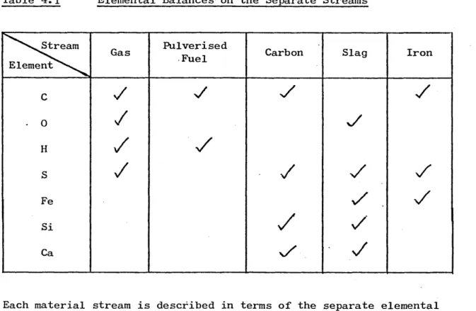
on the separate streams as indicated in Table 4.1.
Table 4.1 Elemental Balances on the Separate Streams
Pulverised Fuel
Stream Gas Carbon Slag Iron
Element
Fe
Si Ca
Each material stream is described in terms of the separate elemental
flows contained within it, the elemental flow of nitrogen in the gas phase being considered constant throughout the reactor. All the other
elemental flows are allowed to vary throughout the reactor, the separate
elements carried into and out of the slice in the separate streams.
The model assumes that material enters the reactor as oxygen, nitrogen,
fuel oil, pulverised fuel, ore, coal and limestone. The oxygen and nitrogen, not in the standard air ratio but in a variable ratio to
simulate varying operating ratios of oxygen to air, are assumed to
enter the gas stream at slice zero, but all other material inputs can
be distributed along the length of the reactor. This allows the model
to simulate different operating practice. For example, the combustion mixing produced by the burner is simulated by assuming that the fuel
oil enters the gas phase uniformly over the first 60 slices burning
immediately and liberating its heat of combustion directly into the gas phase. The pulverised fuel is assumed to enter its own stream uni
formly over the first 90 slices, this distance being chosen to simulate
the way in which the fuel injector mixes the pulverised fuel into the bulk gas stream. The combustion of the pulverised fuel is subsequently
analysed as described later. The inputs of coal to the carbon phase
and ore and limestone to the slag phase can be distributed uniformly along the length of the reactor or given a triangular distribution with
the maximum input rate placed at any point within the reactor, depend
ing on the actual feed mechanism being simulated by the model.
In writing the heat and elemental balances on each stream in each slice,
it is assumed that the interchange between adjacent slices is only brought about by the material flows from one slice to the adjacent
slice, conduction and diffusion axially along the reactor being ignored.
Interchange between the different streams is thus described in each heat
The iron stream is assumed to lie against the wall of the reactor, maintained in place by the centripetal force of the rotating reactor.
The slag layer lies against the iron layer and the solid carbon bed
(of coal) floats on the slag layer. The centre of the reactor is occupied by the gas stream, with the pulverised fuel stream incorpor
ated into it.
The different interchange processes considered in the model are listed below.
4.1.1 Heat Transfer
(a) From gas to carbon
This interchange is assumed to occur by convection and radiation.
Calculation of the radiation transfer rate is described in Appendix 1.
The convective heat transfer coefficient was calculated using standard
pipe flow correlations; e.g. the Dittus-Boelter
equation:-Nu = 0.023 Re° ’ 8 Pr° * 3 (4.l)
augmented in the light of the mass transfer studies carried out in this
work. However, even the augmented convective heat transfer was too small to produce heat flows that were significant in the presence of
the calculated radiation fluxes.
(b) From carbon to slag
The transfer of heat from the carbon to the slag layer is brought about
by conduction through the solid coal, and was analysed in terms of a . 2 6
coke conductivity and the thickness of the coal bed. Thus the model
would rotate or partially sink, enhancing the flow of heat from the
hot gas above them to the somewhat cooler slag. This enhancement was arbitrarily modelled by augmenting the thermal conductivity of the coal
particles in the model.
(c) From slag to iron and iron to the water cooled shell
Both these heat transfer processes took place by conduction, composite
thermal resistances being calculated for the transfer from the bulk slag
to the bulk iron, and from the bulk iron through the lining to the water
cooled shell of the reactor which was assumed to be at 100 °C. The
resistances of the slag and iron layers involve the layer thicknesses. Values were chosen from plant observation and were never altered.
(d) Heat transfer with mass interchanges
Each mass exchange from one stream in any one slice to another stream in the same slice was always assumed to carry with it the sensible heat
content corresponding to the stream from which it originated.
4.1.2 Carbon Transfer
(a) From pulverised fuel to the gas stream
This interchange was involved in the combustion of the pulverised coal,
assumed to be a diffusion limiting process, and detailed in Appendix 2.
(b) From the carbon bed to gas stream
The transfer of carbon from the carbon bed to the gas stream is brought
about, in part, by the combustion of the coal. This is a function of
the surface reaction rate constant (see Appendix 2), and the rate at
which the oxidising gases reach the coal surface from the gas core. In
that:-Sh = k.R.-e-.d 1_____ (4.2) D.1
where the Sherwood number, Sh, has been obtained from the standard pipe flow relationship, e.g.
Sh = 0.023 Re0 ! 8 Sc° * 4 (4.3)
augmented in the light of the experiments to be described later.
The flux of any species, i, to the carbon surface is given
as:-ki (pi - xi)
where and are, respectively, the partial pressures of i in the
bulk gas and at the reaction surface.
Now the nett flux of hydrogen and oxygen containing species per atom of hydrogen and oxygen is zero, therefore the rate of carbon oxidation
is equal to the nett flux of carbon containing species.
Thus,
(
X _ - ) + k (x_- P___ J ... (4.4)CO CO) 2 V 2 2 /
K • X_ — k-_ . s 0 CO
v
CO CO. AIf the gases are in equilibrium at the interface, then,
X _ = K . X _ V x ~ C0n p CO 0_ (4.5)^
2 ' 2
Solution of these equations for the interface temperature gives the
rate of coal combustion.
kinetic model assumed for this reaction will be described later.
(c) From the carbon bed to the iron stream
As described subsequently, iron drops are formed by the reaction between
the iron bearing slag and the coal particles in the carbon bed. It is assumed that these droplets contain a fixed proportion of carbon when
they form and thus their passage through the slag into the iron layer
carries the corresponding flux of carbon. The actual proportion of
carbon allotted by the mathematical model was set in the light of plant experience.
(d) From the iron to the gas stream
Under certain operating conditions, the iron layer can become directly
exposed to the gas phase whence carbon can be burnt out of the iron stream. The mechanism of this decarburisation process possibly involves
a carbon boil and is described in the model in terms of a first order
equation, values of the constant in this equation being chosen so that
the carbon levels predicted by the model are in line with those achieved in plant operation.
4.1.3 Oxygen Transfer
(a) From the slag stream to the gas stream
Oxygen is transferred from the slag stream to the gas stream as a result
of the reduction of the iron oxide in the slag. The kinetics of this reaction formed a specific facet of this investigation, and are there
fore described in section 5
-(b) From the gas stream to the slag stream
Under certain operating conditions the gas stream could be highly
gas stream could reoxidise the slag stream. The kinetic equations
used in the model are specified in Appendix
3-4.1.4 Iron Transfer
(a) From the slag stream to the iron stream
Droplets of iron form as the coal particles reduce the iron oxide in the slag stream. The rate at which they form is described, as stated
above, in section 5» Once they are formed, the centripetal force in
the rotating reactor causes the iron droplets to be thrown into the iron layer against the refractory wall.
(b) From the iron stream to the slag stream
Once again, highly oxidising conditions could be built up in the reactor
under certain operating conditions, and could produce highly oxidising
slags. These could reoxidise the iron layer, the equations used in the
model to describe this process being described in Appendix 4.
4.1.5 Coal and Limestone Decomposition
The coal contains volatiles and moisture, silica and lime. An arbitrary
model is assumed for its decomposition: once the coal has been heated to
r °
625 C, after entering the carbon stream, the volatiles and moisture it contains are driven off into the gas stream, and the lime and silica of
its ash content enter the slag stream.
Limestone, added with the coal, is assumed to enter the slag stream
directly where it decomposes5 carbon dioxide entering the gas stream
and the lime produced dissolving in the slag. This decomposition
4.2 Mode of Operation of Model
In principal, the parameters involved in the mathematical model could
be divided into two categories:- parameters fixed as a result of
literature survey or prior laboratory or pilot plant experiment, and parameters that were varied in order to simulate different plant operat
ing conditions. In this latter category were the input rates of fuel oil, pulverised fuel, coal, limestone, oxygen, air and ore, and the
spread of the input materials.
For any given 'run’ of the model, single values of all these parameters were set and the model operated. The output from the model provided
values, in each slice, for the following variables:- the temperatures of the gas, carbon, slag and iron streams; the amounts of iron oxide
reduced and iron oxidised in the slice; the amount of carbon burnt; the depth of the carbon bed; the gas composition and heat losses. Table 4.2
presents a condensed illustration of the output from the model.
As will be described later, comparisons between inferences drawn from
the variables provided by the model and from observations of the per
formance of the pilot plant were used to test and modify the model, and then to understand, and thereby subsequently improve, the performance
KEY TO TABLE 4.2
The colums shown in Table 4.2 are as follows
tg - Temperature of Gas (°C)
tg-c - Temperature of Gas - Carbon Interface (°C)
Tc - Temperature of Carbon (°C)
TC-S - Temperature of Carbon - Slag Interface (°C)
V s
- Temperature of Gas - Slag Interface (°C)Ts
Temperature of Slag (°C)TS-Fe - Temperature of Slag - Iron Interface (°C)
TFe - Temperature of Iron (°C)
TFe-R - Temperature of Iron - Refractory Interface (°C)
Oil - g atoms of carbon m oil per s x 103
P.F. - g atoms of carbon in pulverised fuel per s
Iron Added - g atoms of iron added in iron ore per s x 103
Iron Reduced - g atoms of iron reduced from slag per s x 103
Iron Oxidised - g atoms of iron oxidised from iron layer per s x 103
Coal Added - g atoms of carbon added in coal per s x 103
Coal Burnt - g atoms of carbon combusted from coal layer per s x 10
Cover % - percentage of slag layer covered by coal layer
Depth - thickness of coal layer floating on slag layer (cm)
5 LABORATORY EXPERIMENTS
5-1 Kinetics of the Reduction of Molten Iron Containing
Slags by Solid Carbon
5-1-1 Reaction Kinetics
The reduction of iron oxide from a molten slag using solid carbon is a
heterogeneous reaction, whose rate can be expressed by the
equation:-^ = -A1, k 1. Cn dt (5-1)
where dt is the rate of the reaction, is the actual area of the
reaction interface, C is the molar concentration of the iron containing
species, FeO, in the slag, n is an exponent representing the order of 1 .
the reaction and k is a rate constant. If the reaction is taking
place in a given volume of slag, V, a mass balance on the iron that it contains shows
that:-V dC _ dN (5-2)
dt ~ dt
so that equation (5-l)
becomes:-dC _ A^ 1 n (5.3)
dt " V
1 However, it is seldom possible to measure the actual reaction area, A ,
so that the reaction rate is related to some suitable nominal area, A, and to a corresponding nominal rate constant, k. Thus equation (5-3)