This content has been downloaded from IOPscience. Please scroll down to see the full text.
Download details:
IP Address: 103.31.35.2
This content was downloaded on 02/07/2017 at 05:40
Please note that terms and conditions apply.
Abrasive Wear Failure Analysis of Tungsten Carbide Hard facing on Carbon Steel Blade
View the table of contents for this issue, or go to the journal homepage for more 2017 IOP Conf. Ser.: Mater. Sci. Eng. 165 012020
(http://iopscience.iop.org/1757-899X/165/1/012020)
Abrasive Wear Failure Analysis of Tungsten Carbide Hard
facing on Carbon Steel Blade
A. L. Mohd Tobi1, Z. Kamdi1,M. I. Ismail*,1, M. Nagentrau1, L. N. H. Roslan1, Z. Mohamad1, A. S. Omar1, N. Abdul Latif1
1Faculty of Mechanical and Manufacturing Engineering University Tun Hussein onn Malaysia (UTHM), 86400, Batu Pahat, Johor, Malaysia.
*E-mail: muhdiqzaham@yahoo.com
Abstract. This study investigate the abrasive wear failure of tungsten carbide hardfacing on continuous digester (CD) blade (carbon steel) in an environment of sulphuric acid and ilmenite ore mixture. Comparison being made on the hardness, thickness and microstructural of the hardfacing between unworn and 3 months old worn blade on few locations around the blade. The cross sections of the blade revealed non-uniform coverage of the hardfacing on the blade for both worn and unworn blade. The edge of the blade has the least amount of hardfacing thickness which with time acts as the point of failure during the wear process. The hardness obtained from both the unworn and worn samples are around 25% lower from the hardfacing electrode manufacturer’s hardness specification. Microstructural micrograph analysis of the hardfacing revealed non uniform size carbide with non-uniform distributed of carbide in the hardfacing layer.
1. Introduction
Wear is the degradation material from friction or when two surface slide together that could lead to a failure point of the component. Wear of machine part and component is one of the major problem faced by the industry in our world. Furthermore, the material to reduce the wear rate and increase the life of the component is being investigated and needed by all of the industry. Moreover, Wear component also could lead in increasing the maintenance cost of the component to the company.
Hardfacing is a process of depositing a material on a component by using certain method such Welding, thermal spraying and cladding. Hardfacing process is one of the method that will add a coating layer that act as a protective layer that will reduce the wear rate and increase the component life. Furthermore, the hardfacing alloys show clear superiority in abrasive wear resistance in contrast to unhardfaced alloy [1]. But the effect of hardfacing on component life and performance will depend upon the hardfacing material and the application process [2]. The high hardness that protective layer poses is one of the factors that help improve in abrasive wear of material that reduce the wear rate [3-4].
Shielded metal arc welding (SMAW), or also known as manual metal arc welding(MMAorMMAW),flux shielded arc weldingor informally asstick welding, is a manual
arc
welding
process that uses a consumableelectrode
covered with afflux to lay the weld. SMAW ismuch cheaper than other type of fusion welding such as Gas–metal arc welding, Plasma arc welding, Electro-slag welding and many more which require more specific expensive tools and equipment. SMAW is one of the way of hardfacing. Furthermore, hardfacing SMAW applications gives more importance to the economical and metallurgical aspects, looking for a balance between quality and efficiency [5].
Tungsten carbide (WC) had been wide used by industry and still now it is being investigated. Tungsten carbide is one of the hard material that have a good properties to act as a protective coating layer on a component to increase wear resistance. Furthermore, Tungsten Carbide (WC) have a high
International Conference onApplied Science(ICAS2016) IOP Publishing IOP Conf. Series: Materials Science and Engineering 165(2017) 012020 doi:10.1088/1757-899X/165/1/012020
hardness properties with low wear rate, it has become one of the material that are used in hardfacing. The wear resistance of any alloy will increase when WC particles existed at the coating [6]. Furthermore, an addition of WC in coating can increases the micro hardness of the coating [7]. Higher carbide contain will have a higher hardness thus will increase the wear resistance. Moreover, the size of tungsten carbide particle and the distribution of tungsten carbide through the coating layer is one of the effecting properties that effect the hardness. Better distribution or finer grain of carbide will give a better hardness. Moreover, the microstructure characteristic such as the type, amount, size, and the distribution of carbides, has a great influenced and effect on the wear property. [8-9]
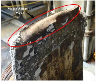
[image:3.595.135.454.314.586.2]The major purpose of the continuous digester blade are to mix the ilmenite and sulphuric acid (H2SO4) to produce titanium dioxide. The acidic and abrasive properties of the mixture causes the blade to wear. The CD blade are hardface by Tungsten Carbide (WC) electrode using SMAW method to increase the wear resistance of the blade. Figure 1 shows the condition of the blade after 6 month of process. The red circle shows the major abrasion occurs on the blade. Moreover, the other part also shown an abrasion wear occurs but the wear are just minor wear. In this study, the blade will be investigated on coating thickness, hardness, and microstructure.
Figure 1: Blade Condition after 6 Month of Process.
2. Methodology
2.1 Material and hardfacing welding
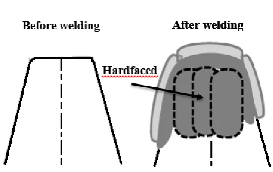
The substrate or blade material used in CD blade are carbon steel. Figure 2 shows the illustration of the blade before the after hardfacing process. The size of the blade is approximately 370 mm times 955 mm and the thickness are range between 25-30 mm. Even though the blade is already hard, the hardfacing still need to be done cause by the acidic and abrasive factors occurs during the digestion process.
The hardfacing process of the CD blade was done continuously until one whole blade is complete hardfaced. Before the hardfacing process, the electrode (WC) will be dry in the oven for 0.5 to 1.0
Major Abrasion
Wear
International Conference onApplied Science(ICAS2016) IOP Publishing IOP Conf. Series: Materials Science and Engineering 165(2017) 012020 doi:10.1088/1757-899X/165/1/012020
hours at the temperature 80-120 °C. Table 1 shows the chemical composition of the electrode used for hardfacing. The hardfacing process will be conducted by the company welder using 300-320 DC current range with direction flow of weld from top to down, with the average slag size of 30 to 40 mm produce. The blade are weld part by part until all the hardfacing is done, refer Figure 4 for complete hardfacing process.
In this study, two blade with different time process are investigated. New unworn blade and worn blade that had been used for 3 month. New unworn blade is a blade that not being used yet for the digestion process, while the 3 month worn blade is a blade that had been used for three month in the digestion process. Both of the blade was hardfaced with the same parameter and same welding method. The blade are hardfaced by the company welder.
Table 1: Chemical Composition of Electrode Chemical composition
C 3.2
Si 0.4
Mn 1.5
W 54.2
[image:4.595.153.431.328.503.2]Fe bal
Figure 2: Blade illustration Condition before Hardfacing and after Hardfacing Process.
2.1 Sample Preparation
The hardfaced blade was section into 7 section 1, 2, 3, 4, 5, 6 and 7. All the seven section are cut by Electrical Discharge Machining (EDM) wire cut. Before cutting process, the blade need to undergo cleaning process by removing the slag obtain by welding process. The seven section of the sample are being selected throughout the blade as shown in Figure 3.
Figure 3: Blade sectioning and numbering specimen
2.2 Coating thickness, Hardness, and Microstructure analysis
All sample are grind using sand paper from grit 200, 400, 600, 800, 1200, and 1500 and are polish using polisher with additional of alumina for microstructure analysis. The microstructure are observe using Scanning Electron Machine (SEM) and Optical Microscope (OM). While the Coating thickness are measured using image J software (commercial image software). The sample are capture with a measurement instrument (ruler) and the measurement instrument will be the indicator of the measurement. The micro hardness of substrate and WC are being tested by Vickers Hardness using load 0.5HV and the dwelling time of 15 s. 3 readings are taken for each specimen and an average reading are calculated as the final hardness.
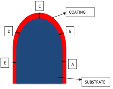
Each of the specimen the coating thickness are measured at 5 different points A, B, C, D, and E using image J. Figure 4 shows the 5 points of coating thickness measured. The red colour region are the coating while the blue colour region are the substrate.
Figure 4: The Positon of the Coating Thickness Measure
International Conference onApplied Science(ICAS2016) IOP Publishing IOP Conf. Series: Materials Science and Engineering 165(2017) 012020 doi:10.1088/1757-899X/165/1/012020
[image:5.595.197.396.586.742.2]3. Result and Discussion
3.1 Coating thickness
Each of the specimen the coating thickness are measured at 5 different points A, B, C, D, and E using image J. Figure 4 shows the 5 points of coating thickness measured. The red colour region are the coating while the blue colour region are the substrate.
From unworn coating thickness result Figure 5, it shows a W shape pattern of thickness. From all the 5 points, it shows that points B and D shows the lowest coating thickness compare to points A, C, and E. The W shape pattern shows at sample 1, 2, 6, and 7. While Sample 3, 4, and 5 shows almost a straight line pattern where it have a same coating thickness through all the points. Furthermore, only sample 4 that have not coating at all at point C.
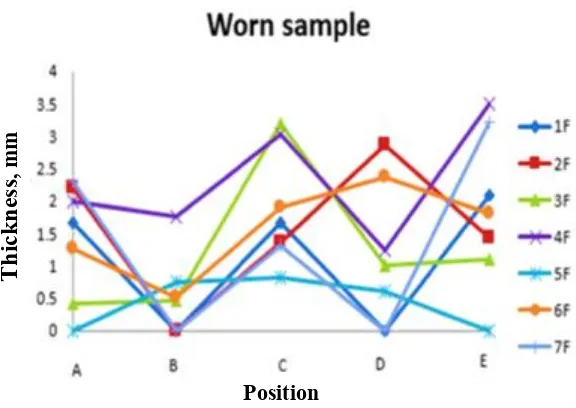
From worn coating thickness result Figure 6, it also show a W shape pattern of thickness but the coating thickness are less than coating thickness of unworn blade. Furthermore, at point B and D the coating thickness are almost zero.
[image:6.595.146.441.402.594.2]Furthermore, effect from the low coating thickness, Point B, and D have the possibilities to become the point of failure of the blade and cause early damage after the coating loss, but coating thickness will not affect much on coating hardness [10]. Figure 7 shows the illustration of the hardfaced blade, the red arrow point at the edge of the blade that have low coating thickness are the place where points B and D are situated on the blade.
Figure 5: Coating Thickness Result on Unworn Blade
Position
T
h
ickn
ess
, m
m
Figure 6: Coating Thickness Result on Worn Blade
Figure 7: The Observation of the Early Damage of Abrasion Wear
3.2. Hardness
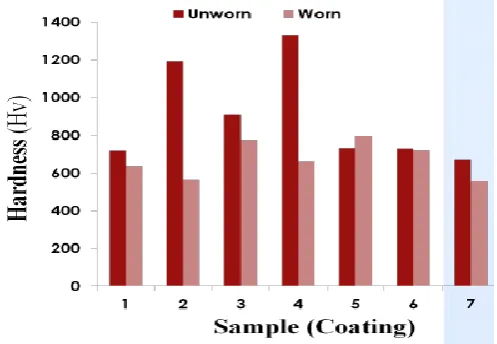
The hardness test was done on two condition, at the substrate and the coating of the blade. Figure 8 shows the result for substrate on both of the blade and Figure 9 shows the result for coating for both blade also. The substrate hardness for worn and unworn blade is approximately at 230 HV. The substrate hardness pattern shows a slightly increase in hardness for all sample for worn blade. Furthermore, The coating hardness for worn and unworn blade are approximately at 750 HV, but at sample 2 and 4 the hardness value for coating are approximately at 1200 HV. Moreover, the coating hardness pattern shows that the unworn blade has a slightly higher hardness than worn blade.
Position
T
h
ickn
ess
, m
m
International Conference onApplied Science(ICAS2016) IOP Publishing IOP Conf. Series: Materials Science and Engineering 165(2017) 012020 doi:10.1088/1757-899X/165/1/012020
[image:7.595.139.454.366.527.2]Figure 8: Hardness at Substrate for Worn and Unworn Blade
Figure 9: Hardness at Coating Surface for Worn and Unworn Blade
3.3. Microstructure
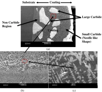
The micrograph of the coating of the blade are shown on Figure 10. There are three types of tungsten carbide microstructure that are present at the coating, large carbide, small carbide and Non carbide Region. The hardness of the coating are constant except sample 2 and 4, it shows that the hardness test conducted might land on the large carbide size that have a higher hardness. Furthermore, to achieve best wear resistance, a high content of tungsten carbides which are uniformly distributed within the microstructure is necessary [11-12]. Higher contain of carbide will give higher hardness value. Furthermore, higher carbide contain with finer grain of microstructure will produce a higher hardness value and increase wear resistance. The result shows that the value of hardness obtain except sample at position 2 and 4 decrease about 25% from the hardfacing electrode manufacturer’s hardness specification. New hardfacing process need to be introduce to overcome this problem.
[image:8.595.172.421.341.513.2](a)
[image:9.595.109.502.91.443.2](b) (c)
Figure 11: Interface microstructure of substrate and coating (WC) at point C (a) Needle like of WC microstructure
(b), (c)
4. Conclusion
In this study, the continuous digester blade that was used in the digestion process of titanium dioxide has been analyzed. The digester blade was made up from the carbon steel and coated with tungsten carbide (WC) based materials. The main purpose of this study was to characterized and compared the used with the new digester blade. The following conclusion can be drawn from this study:-
Inconsistent thickness of coating around the blade along position A until E, due the inconsistent welding of the coating.
Both worn and unworn blade has minimum thickness located at edges B and D of the cross sections due to improper weld at edge location. This could lead to insignificant factors during operation to edges B and D that will be exposed to abrasive environment and the coating might wear, thus unable to give protection to the blade.
Edge B and D will act as the point of failure upon further wear.
The carbide distribution along the coating area was not fully participated at the coating area. This will give impact to the original hardness that should be obtain by the blade to reduce wear rate.
Substrate
Non Carbide
Region
Small Carbide
(Needle like
Shape)
Large Carbide
Coating
Coating
International Conference onApplied Science(ICAS2016) IOP Publishing IOP Conf. Series: Materials Science and Engineering 165(2017) 012020 doi:10.1088/1757-899X/165/1/012020
The welding parameter used by the industry does not follow the actual parameter according to the actual specs, this could be also one of the reason and factors that cause the major reduce in the hardness value for the unworn blade.
References
[1] Amardeep S K, Gurmeet S C, Shivali S, 2014, Wear Behavior of Hardfacings on Rotary Tiller Blades, Procedia Engineering 94, 1442-1451.
[2] Vineet S, Vikas C, 2013, Enhancement in Wear Resistance by Hardfacing: A Review, ISSN 2, 2320-2491.
[3] Jun L, Shuai Y, Weisheng X, Xin J and Chibin G, 2016, Microstructure and Wear Resistance Performance of Cu-Ni-Mn Alloy Based Hardfacing Coating Reinforced by WC Particles, Journal of Alloy and Compound 654, 63-70.
[4] Xin L, Liang L, Xiaoqiang L, Yuanyuan L, (2015) Abrasion Wear Behaviour of Wc–10ni3al Cermet with Plate-Like Triangular Prismatic Wc Grains, ceramic international 41, 5147– 5158.
[5] Amado C C, Americo S, Manuel R P, 2008, Operational Behavior Assesment of Coated Tubular Electrodes for SMAW Hardfacing, 265-273.
[6] P. Wu, H.M. Du, X.L. Chen, Z.Q. Li, H.L. Bai, E.Y. Jiang, 2004, Influence of WC particle
behavior on the wear resistance properties of Ni–WC composite coatings, 257 Wear, 142–
147.
[7] S. Harsha, D.K. Dwivedi and A. Agrawal, 2007, Influence of WC addition in Co–Cr–W–Ni–C flame sprayed coatings on microstructure, microhardness and wear, behaviour Surface & Coatings Technology 201, 5766 – 5775
[8] V.M. Desai, C.M. Rao, T.H. Kosel, N.F. Fiore, 1984, Wear 94, 89. [9] H.R. Shetty, T.H. Kosel, N.F. Fiore, 1982, Wear 80, 347.
[10] Hongxia Deng, Huiji Shi, Seiji Tsuruoka, 2010, Influence of coating thickness and temperature
on mechanical properties of steel deposited with Co-based alloy hardfacing coating, Surface & Coatings Technology 204, 3927–3934.
[11] K. Van Acker, D. Vanhoyweghen, R. Persoons, J. Vangrunderbeek, 2005, Influence of tungsten carbide particle size and distribution on the wear resistance of laser clad WC/Ni coatings, Wear 258, 194–202.
[12] E. Badisch, M. Kirchgaßner, 2008, Influence of welding parameters on microstructure and wear
behaviour of a typical NiCrBSi hardfacing alloy reinforced with tungsten carbide, Surface & Coatings Technology 202, 6016-6022.