VIBRATION SIMULATION OF A SIMPLY-SUPPORTED BEAM WITH ATTACHED MULTIPLE ABSORBERS
MOHD AZLI BIN IDRIS
A thesis submitted in
fulfillment of the requirement for the award of the Degree of Master of Mechanical Engineering
Faculty of Mechanical and Manufacturing Engineering Universiti Tun Hussein Onn Malaysia
ABSTRACT
In general, the standard solutions to reduce the vibration and noise problems are to redesign and modify the system such as adding the thickness of wall panels, enhancing the elasticity of the structure and increase the damping mechanism of the structure. In this study, the concept of dynamic vibration absorber is used on a beam structure to re-duce the vibration or amplitude. The methods employed in this study were analytical equations and finite element analysis. MATLAB® was used to transform analytical equations into graphs and at the same time to verify the finite element simulation of ANSYS®. Result shows that analytical equation and finite element simulation of a simply supported beam produce a similar outcome, which indicates a good agreement. The frequency range was studied between 5 Hz to 1000 Hz and there are four modes resulting shape. Further study was conducted by placing the absorber at different lo-cations configuration. This was followed by adding a single absorber and multiple absorbers to see the average percentage reduction in vibration’s amplitude. The over-all reduction achieved for multiple absorbers is 88.6% compared to a single absorber which only achieved 8.21% reduction. Finally, it can be concluded that multiple vi-bration absorber can be reduce the global vivi-bration of structure compared to a single vibration absorber. However, for the structures that concern about weight, adding more dynamic vibration absorber needs to be considered properly since excess weight will result in less fuel efficiency of vehicles, aerospace, automotive and machine systems.
ABSTRAK
Pada umumnya, penyelesaian bagi piawaian untuk memperbaiki masalah getaran dan kebisingan adalah dengan merekabentuk semula dan mengubah suai sistem seperti menambah ketebalan pada dinding panel, mempertingkatkan keanjalan struktur, dan menambah mekanisma redaman pada struktur. Maka dalam kajian ini, konsep peny-erap getaran dinamik digunakan untuk mengurangkan getaran atau amplitud. Pada sesuatu struktur rasuk, kaedah yang digunakan dalam kajian ini adalah persamaan anal-itikal dan analisis unsur terhingga. MATLAB® digunakan untuk menyelesaikan teori persamaan analitikal, disamping mengesahkan keputusan simulasi ANSYS®. Kepu-tusan kajian mendapati persamaan analitikal dan simulasi rasuk yang disokong mudah adalah sama. Julat frekuensi adalah 5 Hz hingga 1000 Hz dan terdapat empat ben-tuk mod yang terhasil. Seterusnya, kajian ini dijalankan dengan meletakkan penyerap pada lokasi yang berlainan konfigurasi. Ini diikuti dengan penambahan penyerap tung-gal dan penyerap berganda untuk melihat peratusan purata pengurangan getaran atau amplitud. Pengurangan global keseluruhan bagi penyerap berganda adalah 88.6%% berbanding dengan penyerap tunggal yang hanya 8.21% pengurangan. Akhirnya, da-pat disimpulkan bahawa penyerap getaran berganda dada-pat mengurangkan keseluruhan getaran global berbanding dengan penyerap tunggal. Walaubagaimanapun, bagi struk-tur yang mengambil kira berat sebagai perkara utama penambahan bilangan penyerap perlu dipertimbangkan kerana penambahan berat yang berlebihan pada struktur akan mengakibatkan pengurangan kecekapan bahan api pada kenderaan, aeroangkasa, sis-tem automotif dan mesin.
CONTENTS
DECLARATION ii
DEDICATION iii
ACKNOWLEDGMENT iv
ABSTRACT v
ABSTRAK vi
LIST OF FIGURES ix
LIST OF TABLES xii
LIST OF APPENDICES xiii
LIST OF SYMBOLS 1
CHAPTER 1 INTRODUCTION 1
1.1 Research Background 1
1.2 Problem Statement 2
1.3 Objectives of Study 2
1.4 Scopes of Study 3
1.5 Expected Outcomes 3
1.6 Significant of Study 3
CHAPTER 2 LITERATURE REVIEW 5
2.1 Vibration 5
2.1.1 Classification of Vibration 5
2.1.2 Elementary Parts of Vibrating System 6
2.1.3 Periodic Motion 7
2.1.4 Discrete and Continuous System 8
2.1.5 Natural Frequency 9
2.1.6 Modes Shape 9
2.2 Vibration Analysis 12
2.3 Dynamic Vibration Analysis (DVA) 13
2.4 Finite Element Analysis (FEA) 17
2.5 MATLAB 19
2.5.1 The Advantages of MATLAB 19
2.6 Previous Study 21
CHAPTER 3 METHODOLOGY 23
3.1 Research Flow Chart 24
3.2 Theoretical Equation 25
3.2.1 Simply-Supported Beam 25
3.2.2 Spring-Mass-Damper 27
3.2.3 Simply-Supported Beam With Attached
Spring-Mass-Damper System 28
3.3 ANSYS Software 32
3.3.1 Procedure 32
3.4 MATLAB® Software 40
3.4.1 Procedure 40
CHAPTER 4 RESULTS AND DISCUSSION 44
4.1 Analysis of Simply-Supported Beam 44
4.2 Analysis of Simply-Supported Beam with Attached SMD
System 49
4.3 Comparison With and Without SMD Attachment on
Simply-Supported Beam 52
4.4 Different Location of SMD 53
4.5 Multiple SMD on Simply-Supported Beam 58
CHAPTER 5 CONCLUSION AND RECOMMENDATION 64
5.1 Conclusion 64
5.2 Recommendations 65
REFERENCES 66
VITA 133
LIST OF FIGURES
FIGURE NO TITLE PAGE
2.1 A deterministic (periodic) excitation 6
2.2 Random excitation 6
2.3 Elementary parts of vibrating systems 6
2.4 The motion in the centre of the string 10
2.5 The two halves of the string vibrate in opposition each other 10 2.6 The string is divided into three equal length sections 10
2.7 The string mode with difference frequencies 11
2.8 Input-output relationship of a vibratory system 12 2.9 Illustration of the principle of the dynamic vibration absorber 13 2.10 Theoretical transmissibility curves for a vibration isolated system
supplied with an undamped dynamic vibration absorber 15 2.11 Effect of extreme absorber damping upon the transmissibility
ra-tio of an undamped machine/isolator system 15 2.12 Transmissibility of a machine/isolator system when the machine
is supplied with a damped vibration absorber. The degree of
damping is indicated on the curves 16
2.13 Curve showing "optimum" viscous damping factor as a function
of the mass ratio 16
2.14 Theoretical transmissibility curves for a system of the type shown in Figure 2.9 supplied with a viscously damped dynamic vibration absorber. Optimum absorber tuning and damping for mass ratios
of Mm =0.1, Mm =0.2, Mm =0.5 17
2.15 Dynamic vibration absorber applied to: a) Machine (source), b)
Equipment 17
3.1 Research flow chart 24
3.2 Schematic of simply-supported beam 25
3.3 Single DOF spring-mass-damper system 27
3.4 Schematic of simply-supported beam with SMD System attached 29
3.5 The main screen of MATLAB® 40
3.6 Open “New Script” 41
3.7 Type “clear” on the Editor screen 41
3.8 Type “clc” on Editor screen 42
3.9 Writing the programming code 42
3.10 Select the “Run” icon 43
3.11 The final result 43
4.1 Schematic of simply-supported beam 44
4.2 FE model of simply-supported beam 45
4.3 First mode of simply-supported beam 45
4.4 Second mode of simply-supported beam 46
4.5 Third mode of simply-supported beam 46
4.6 Fourth mode of simply-supported beam 47
4.7 Frequency response of simply-supported beam 47
4.8 Frequency response function of simply-supported beam 48
4.9 Frequency phase of simply-supported beam 48
4.10 Schematic of simply-supported beam with SMD system attached 49 4.11 FE model of simply-supported beam with an attached SMD system 50 4.12 Schematic of simply-supported beam with SMD system attached 50 4.13 Frequency response function of simply-supported beam with
at-tached SMD 51
4.14 Frequency phase of simply-supported beam with and without
at-tached SMD 51
4.15 Comparison of simpy-supported beam with and without SMD. 53 4.16 Schematic of simply-supported beam without SMD 53
4.17 Schematic of first location (left) 54
4.18 FE model of simply-supported beam with an attached SMD
sys-tem (left) 54
4.19 Schematic of second location 2 (middle) 54
4.20 FE model of simply-supported beam with an attached SMD
sys-tem (middle) 55
4.21 Schematic of third location (right) 55
4.22 FE model of simply-supported beam with an attached SMD
sys-tem (right) 55
4.24 Graph average of reduction with differences location 56 4.23 Frequency response of simply-supported beam with differences
location of SMD system 57
4.25 Schematic of simply-supported beam attached with two SMD 58 4.26 Schematic of simply-supported beam attached with three SMD 58
4.27 Schematic of simply-supported beam attached with four SMD 58 4.28 Schematic of simply-supported beam attached with five SMD 58 4.29 Schematic of simply-supported beam attached with six SMD 59 4.30 Schematic of simply-supported beam attached with seven SMD 59 4.31 Schematic of simply-supported beam attached with eight SMD 59 4.32 Schematic of simply-supported beam attached with nine SMD 59 4.33 Schematic of simply-supported beam attached with ten SMD 60 4.34 Frequency response of simpy-supported beam with with multiple
SMD 61
4.35 Graph average of reduction for multiple SMD 63
LIST OF TABLES
TABLE NO TITLE PAGE
3.1 Parameters used in the analysis of a simply-supported beam 25 3.2 Parameters used in the analysis of a single DOF
spring-mass-damper system 27
4.1 Resonance frequencies (Hz) of a simply-supported beam 49 4.2 Resonance frequencies (Hz) of a beam with attached SMD 52 4.3 Percentage reduction of simply-supported beam between with and
without absorber 53
4.4 The average percentage reduction of vibration 56 4.5 The average percentage reduction of vibration for multiple SMD 62
LIST OF APPENDICES
APPENDIX TITLE PAGE
A Ansys® Coding 69
B Matlab® Coding 112
CHAPTER 1
INTRODUCTION
1.1 Research Background
Vibration is the mechanical oscillations, that produced by the regular or irregular mo-tion of a particle or a body or systems that connected bodies displaced from a posimo-tion of equilibrium. Vibration can be a source of problem at an engineering level because resulting in damage and loss of control of equipment and thus reducing the efficiency of operation in machines. They are produce increased stresses, energy losses, because added wear, increase hearing loads, induce fatigue, create passenger discomfort in ve-hicles and absorb energy from the system. Vibration can also cause discomfort at a low-high level that can be risk to the person safety[1][2].
Each vibration structure has tendency to oscillate with large amplitude at cer-tain frequencies. These frequencies are known as resonance frequencies or natural fre-quencies of the structure. At these resonance frefre-quencies, even a small periodic driving force can result in large amplitude vibration. When resonance occurs, the structure will start to vibrate excessively.
The primary method of eliminating vibration is at a source by designing the equipment and ensuring control over the manufacturing tolerances. Others method that can reduce the vibrations that generated by machinery is by modifying the system so that the natural frequencies are not close to the operating speed, to prevent large responses by including damping, install vibration isolating devices between adjacent sub-systems and the other way is include auxiliary mass into the equipment to reduce the response and absorb vibration [3].
This research aims to develop a new control strategy using multiple vibration absorbers attached to a flexible beam and tuned to operational frequency, in such a
2 way to counter the vibrating force across the structure globally. The properties of the absorbers are also adapted in order to minimize the vibration level of the structure at the maximum performance.
1.2 Problem Statement
When a system begins to operate, the structure or machine experience vibration may exist and occur because of the dynamic effects on manufacturing, tolerance, rotation, friction or impact on the machine parts. Critical problems occur is increased number of dynamic systems, such as the mechanical equipment, machinery, bridges, vehicles and aircraft.
In this study, the problem of vibration of the beam structure will be reviewed by put vibration absorber configurations on different locations. This followed, using some of the shock absorber to reduce overall vibration in a simply supported beam structure.
1.3 Objectives of Study
The objective of this research is to study and simulate the vibration characteristics of a vibration of a simply supported beam without and with attached multiple absorbers. Based on the research, there are several objectives that need to achieve.
i. To determine the vibration reduction of a single vibration absorber attach to a beam
ii. To investigate the effect of changing the location (absorber), mass and damping on the absorber performance.
iii. To determine the effect of attaching multiple vibration absorbers to reduce vi-bration level of a simply supported beam.
3
1.4 Scopes of Study
The research is limited according to the scopes below: i. Two approach will be carried out with
• numerical simulation works by ANSYS® • analytical analysis by MATLAB®
ii. Two mathematical models regarding simply–supported beam and when attached absorber will be derived.
iii. The dimension of a beam to be studied 1 x 0.2 x 0.02 m. iv. The number of absorbers to be studied will be limited to 10.
v. Literature search will be carried out on finite element analysis (Ansys), analyti-cal analysis (Matlab), vibration, a simply supported beam, vibration absorbers, natural frequency, damping and mode shape.
1.5 Expected Outcomes
There are several contributions to the body of knowledge presented in this research are: (1) the developments of multiple passive vibration absorbers which are used to target wide frequency range are able the reduce the global vibration of the structure, (2) provide guidelines for optimum numbers of passive vibration absorbers used and its placement in order to have substantial vibration attenuation.
1.6 Significant of Study
4 Vibration also can be harmful and therefore should be avoided. The most ef-fective way to reduce unwanted vibration is to suppress the source of vibration. Above this condition, this research was carried out to understand the vibration characteristic in order to design a dynamic vibration absorber due to the needs of vibration protec-tion itself. As a result, it gave an idea on how to produce an effective absorber. The knowledge gained from this research can be used to minimize the vibration amplitude of a structures and machines, increasing their life-span simultaneously.
CHAPTER 2
LITERATURE REVIEW
This chapter explains about vibration theory, vibration control, Finite Element Anal-ysis (FEA), MATLAB,Dynamic Vibration Absorber (DVA) and previous research on the dynamic absorber.
2.1 Vibration
Vibration is a periodic motion of the particles of an elastic body or medium in alter-nately opposite directions from the position of equilibrium where that equilibrium has been disturbed. The physical phenomena of vibration that take place more or less reg-ularly and repeated themselves in respect to time are described as oscillations. In other words, any motion that repeats itself after an interval of time is called vibration or os-cillation. The theory of vibration deals with the study of oscillatory motion of bodies and the associated forces [4].
2.1.1 Classification of Vibration
Vibrations can be classified into three categories: free, forced, and self-excited. Free vibration of a system is vibration that occurs in the absence of external force. An external force that acts on the system causes forced vibrations. In this case, the exciting force continuously supplies energy to the system. Forced vibrations may be either deterministic or random (see Figure 2.1 and 2.2). Self-excited vibrations are periodic and deterministic oscillation. Under certain conditions, the equilibrium state in such a vibration system becomes unstable, and any disturbance causes the perturbations to grow until some effect limits any further growth. In contrast to forced vibrations,
6 the exciting force is independent of the vibrations and can still persist even when the system is prevented from vibrating [5].
[image:16.595.224.416.271.371.2]Figure 2.1: A deterministic (periodic) excitation
Figure 2.2: Random excitation
2.1.2 Elementary Parts of Vibrating System
In general, a vibrating system consists of a spring (a means for storing potential en-ergy), a mass or inertia (a means for storing kinetic enen-ergy), and a damper (a means by which energy is gradually lost) as shown in Figure 2.3. An undamped vibrating system involves the transfer of its potential energy to kinetic energy and kinetic energy to po-tential energy, alternatively. In a damped vibrating system, some energy is dissipated in each cycle of vibration and should be replaced by an external source if a steady state of vibration is to be maintained [5].
[image:16.595.235.398.618.717.2]7 2.1.3 Periodic Motion
When the motion is repeated in equal intervals of time, it is known as periodic motion. Simple harmonic motion is the simplest form of periodic motion. If x(t) represents the displacement of a mass in a vibratory system, the motion can be expressed by the equation
x=Acosωt =Acos2πt
τ (2.1)
whereA is the amplitude of oscillation measured from the equilibrium of the mass. The repetition time,τ is called the period of the oscillation, and its reciprocal,
f = 1
τ is called the frequency. Any periodic motion satisfies the relationship
x(t) =x(t+τ) (2.2)
That is Period,
τ= 2π
ω s/cycle (2.3)
Frequency
f = 1 τ =
ω
2πcycles/s,or.Hz (2.4)
ω is called the circular frequency measured in rad/sec.
The velocity and acceleration of a harmonic displacement are also harmonics of the same frequency, but lead the displacement by π
2 and π radians, respectively. When the acceleration ¨X of a particle with rectilinear motion is always proportional to its displacement from a fixed point on the path and is directed towards the fixed point, the particle is said to have simple harmonic motion [5].
8
x(t) = a0 2 +
∞
∑
n=1
(ancosnωt+bnsinnωt) (2.5)
Whereω = 2π
τ is the fundamental frequency and a0,a1, a2, ...,b1,b2,. . . are constant
coefficients, which are given by:
a0= 2 τ
ˆ τ
0
x(t)dt (2.6)
an= 2 τ
ˆ τ
0
x(t)cos.nωtdt (2.7)
bn=
2 τ
ˆ τ
0
x(t)sin.nωtdt (2.8)
The exponential form ofx(t)is given by:
x(t) = ∞
∑
n=-∞
cneinωt (2.9)
The Fourier coefficientscncan be determined, using
cn= 1 τ
ˆ τ
0
(x)te−inωtdt (2.10)
The harmonic functionsan cosnωt orbnsinnωt are known as the harmonics of order n of the periodic functionx(t). The harmonic of ordernhas a period τ
n. These
harmonics can be plotted as vertical lines in a diagram of amplitude (anandbn) versus
frequency (nω) and is called frequency spectrum.
2.1.4 Discrete and Continuous System
9 systems, and those systems with an infinite number of degrees of freedom are called continuous or distributed systems [5].
2.1.5 Natural Frequency
The natural frequency is the rate at which an object vibrates when it is not disturbed by an outside force. Each degree of freedom of an object has its own natural frequency, expressed as ωn. Frequency is equal to the speed of vibration divided by the
wave-length, ω =v.λ. Other equations to calculate the natural frequency depend upon the vibration system. Natural frequency can be either undamped or damped, depending on whether the system has significant damping. The damped natural frequency is equal to the square root of the collective of one minus the damping ratio squared multiplied by the natural frequency, as shown in Eq.(2.11)
ω
d=√1−ξ2.ω (2.11)
2.1.6 Modes Shape
Any complex body (e.g., more complicated than a single mass on a simple spring) can vibrate in many different ways. There is no one "simple harmonic oscillator". These different ways of vibrating will each have their own frequency, that frequency determined by moving mass in that mode, and the restoring force which tries to return that specific distortion of the body back to its equilibrium position [6].
It can be somewhat difficult to determine the shape of these modes. For exam-ple one cannot simply strike the object or displace it from equilibrium, since not only the one mode liable to be excited in this way. Many modes will tend to excited, and all to vibrate together. The shape of the vibration will thus be very complicated and will change from one instant to the next.
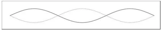
10 Doing this with strings under tension, we find that the string has a variety of modes of vibration with different frequencies. The lowest frequency is a mode where the whole string just oscillates back and forth as one with the greatest motion in the centres of the string as illustrated in Figure 2.4.
Figure 2.4: The motion in the centre of the string
[image:20.595.191.448.376.426.2]The diagram gives the shape of the mode at its point of maximum vibration in one direction and the dotted line is its maximum vibration in the other direction. If we increase the frequency of the jiggling to twice that first modes frequency we get the string again vibration back and forth, but with a very different shape. This time, the two halves of the string vibrate in opposition to each other as shown in Figure 2.5. As on half vibrates up, the other moves down, and are vice versa.
Figure 2.5: The two halves of the string vibrate in opposition each other
[image:20.595.189.448.608.658.2]Again the diagram gives the shape of this mode, with the solid line being the maximum displacement of the string at one instant of time, and the dotted being the displacement at a later instant (180 degrees phase shifted in the motion from the first instant). If we go up to triple the frequency of the first mode, we again see the string vibrating a large amount, example at the resonant frequency of the so called third mode. Figure 2.6 shows the string is divided into three equal length sections, each vibrating in opposition to the adjacent piece.
Figure 2.6: The string is divided into three equal length sections
11 where the quality (in this case the displacement) of a specific mode does not change as the mode vibrates.
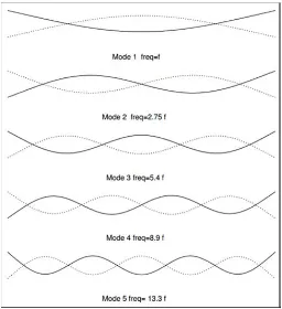
[image:21.595.191.447.362.642.2]The modes of the string have the special feature that the frequencies of all of modes are simply integer multiples of each other. Thenth mode has a frequency of n times the frequency of the first mode. This is not a general feature of modes. In general the frequencies of the modes have no simple relation to each other. As an example let us look at the modes of a vibrating bar free bar. In Figure 2.7, we plot the shape of the first five modes of a vibrating bar, together with the frequencies of the five modes. Again the solid lines are the shape of the mode on maximum displacement in one direction and the dotted the shape on maximum displacement in the other direction. Note that these are modes where the bar is simply vibrating, and not twisting. If one thinks about the bar being able to twist as well, there are extra modes. For a thin bar, the frequencies of these modes tend to be much higher than these lowest modes discussed here. However the wider the bar, the lower the frequencies of these modes with respect to the vibrational modes.
Figure 2.7: The string mode with difference frequencies
12 rapidly damped except the first and fifth modes, which have a node there. Similarly, if one holds the bar in it’s centred, the second, fourth modes both have nodes there while the others do not. Thus only those two will not be damped out.
We note that these modes do not have any nice relation between the frequencies of their modes. We note also that if we strike the bar, we can hear a number of different pitches given off by the bar. For example if we hold it at the 1/4 point, we hear two frequencies, one a very low one and another very high (13.3 times the lowest).
On the other hand if we strike or pluck a string, we hear only one pitch, even if we do not damp out any of the modes. Is there something strange about how the string vibrates? The answer is no. The string vibrates with all of its modes, just as the bar does. It is our mind that is combining all of the frequencies of the various modes into one pitch experience.
2.2 Vibration Analysis
[image:22.595.182.458.533.648.2]A vibratory system is a dynamic system for which the response (output) depends on the excitations (input) and the characteristic of the system (e.g.; mass stiffness and damping) as indicated in Figure 2.8 below. The excitation and response of the system are both time dependent. Vibration analysis of a given system involves determination of the response for the excitation specified. The analysis usually involves mathematical modelling, derivation of the governing equation of motion, solution of the equations of motion, and interpretation of the response results.
Figure 2.8: Input-output relationship of a vibratory system
13 selected, the principles of dynamics are used to derive the equations of motion of the vibrating system. For this, the free-body diagrams of masses, indication all externally applied forces (excitations), reaction forces, and inertia forces, can be used.
2.3 Dynamic Vibration Analysis (DVA)
[image:23.595.219.414.325.475.2]The basic physical principle of the dynamic vibration absorber is that of attaching to a vibrating structure a resonance system which counteracts the original vibrations. Ideally such a system would completely eliminate the vibration of the structure, by its own vibrations. Figure 2.9 illustrates these ideas. The mass, M, is here assumed to be the mass of a (rigid) machine structure producing the vibrating force,P0sin(2πf t) [7].
Figure 2.9: Illustration of the principle of the dynamic vibration absorber
The machine is mounted on a vibration isolator with are stiffness,K. Attached to the machine is a resonance (dynamic absorber) system consisting of the mass, m, and the spring element, k. It is now a simple matter to write down the equations of motion for the complete system:
Md
2x 1
dt2 +Kx1−k(x2−x1) =P0sin(2πf t) (2.12)
md
2x 2
dt2 +k(x2−x1) =0 (2.13) Assuming that the stationary solutions to these equations can be written (whereX1and
14
x1=X1sin(2πf t) (2.14)
and
x2=X2sin(2πf t) (2.15)
then
1+ k
K−M
(2πf)2
K
X1− k KX2=
P0
K (2.16)
and
X1=
1−( f
fa)
2X 2
(2.17)
where fa= 21π
q
k
m= resonant frequency of the attached (absorber) system by setting
1−(ff
a)
2=0 i.e f
a= f motion,X1, of the machine will be zero, i.e. the machine will not vibrate at all. The maximum amplitude of the mass,m, is in this case:
−k KX2=
P0
Ki.e.X2=− P0
K (2.18)
This again means that by tuning the absorber system resonant frequency to equal the "disturbing” frequency, the vibration of the machine can be eliminated.
Actually, in practical cases the "disturbing" frequency region often covers the resonant frequency of the machine-isolator system, and both the absorber and the iso-lation system contain some mechanical damping. The equations of motion for the complete system then become considerably more complex, and so do their solutions.
Figures 2.10, 2.11 and 2.12 illustrate the effects upon the vibration transmis-sibility of a machine/isolator system when the machine is supplied with a dynamic vibration absorber.
From Figure 2.10 it is seen that when the complete system contains no damping at all and the absorber system is tuned to the resonant frequency of the machine/isola-tor system the transmissibility at this frequency is zero, in conformity with the above statements and mathematical derivations. However, on both "sides" of the resonant frequency two, theoretically infinitely high, transmissibility "peaks" are found. The shape of the curve is caused by the dynamic coupling between the machine/isolator system and the absorber system. Coupling effects of this sort are quite common in many branches of physics.
15
Figure 2.10: Theoretical transmissibility curves for a vibration isolated system sup-plied with an undamped dynamic vibration absorber
Figure 2.11: Effect of extreme absorber damping upon the transmissibility ratio of an undamped machine/isolator system
when a damped vibration absorber is applied to a machine/isolator system the trans-missibility curve must lie between the two extremes sketched in Figure 2.11. This is illustrated in Figure 2.12 for various values of absorber damping ratio.
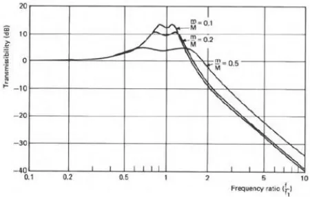
Theory has shown that when damping is added to the absorber the "optimum" performance conditions*) are, in general, no longer obtained by tuning the resonant frequency of the absorber system to equal the resonant frequency of the machine/iso-lator system. Actually the most favourable tuning depends upon the ratio between the absorber mass and the mass of the machine i.e. m /M. It has been found that when the damping is of the viscous type then the ratio between the absorber resonant frequency,
[image:25.595.221.414.292.453.2]16
Figure 2.12: Transmissibility of a machine/isolator system when the machine is sup-plied with a damped vibration absorber. The degree of damping is indi-cated on the curves
fa
f0 =
r
M m+M =
s
1
1+Mm (2.19)
Figure 2.13: Curve showing "optimum" viscous damping factor as a function of the mass ratio
[image:26.595.232.414.388.593.2]17
Figure 2.14: Theoretical transmissibility curves for a system of the type shown in Fig-ure 2.9 supplied with a viscously damped dynamic vibration absorber. Optimum absorber tuning and damping for mass ratios of Mm = 0.1,
m
[image:27.595.149.457.233.412.2]M =0.2, m M =0.5
Figure 2.15: Dynamic vibration absorber applied to: a) Machine (source), b) Equip-ment
The theoretical treatment of the vibration transmissibility from a vibrating source (machine) to its foundation, and that of the vibration transmissibility from a vibrating foundation to mounted equipment is more or less identical. This, of course, also ap-plies with respect to the use of dynamic vibration absorbers see, Figure 2.15.
2.4 Finite Element Analysis (FEA)
18 Finite Element Analysis (FEA) was first developed in 1943 by R. Courant, who utilized the Ritz method of numerical analysis and minimization of variational calculus to obtain approximate solutions to vibration systems. Shortly thereafter, a paper pub-lished in 1956 by M. J. Turner, R. W. Clough, H. C. Martin, and L. J. Topp estabpub-lished a broader definition of numerical analysis. The paper centered on the "stiffness and deflection of complex structures".
By the early 70’s, FEA was limited to expensive mainframe computers gen-erally owned by the aeronautics, automotive, defence, and nuclear industries. Since the rapid decline in the cost of computers and the phenomenal increase in computing power, FEA has been developed to an incredible precision. Present day supercomput-ers are now able to produce accurate results for all kinds of parametsupercomput-ers [8].
19
2.5 MATLAB
MATLAB (short for MATrix LABoratory) is a special-purpose computer program op-timized to perform engineering and scientific calculations. It started life as a program designed to perform matrix mathematics, but over the years it has grown into a flexible computing system capable of solving essentially any technical problem.
The MATLAB program implements the MATLAB programming language and provides a very extensive library of predefined functions to make technical program-ming tasks easier and more efficient. MATLAB is a huge program with an incredibly rich variety of functions. Even the basic version of MATLAB without any toolkits is much richer than other technical programming languages. There are more than 1000 functions in the basic MATLAB product alone, and the toolkits extend this capability with many more functions in various specialties [11].
2.5.1 The Advantages of MATLAB
MATLAB has many advantages compared with conventional computer languages for technical problem solving. These include
1. Ease of Use
MATLAB is an interpreted language, like many versions of Basic. Like Basic, it is very easy to use. The program can be used as a scratch pad to evaluate expressions typed at the command line, or it can be used to execute large prewritten programs. Programs may be easily written and modified with the built-in integrated development environment, and debugged with the MATLAB debugger. Because the language is so easy to use, it is ideal for the rapid prototyping of new programs. Many program development tools are provided to make the program easy to use. They include an integrated editor/debugger, on-line documentation and manuals, a workspace browser, and extensive demos [11].
2. Platform Independence
20 platforms when the needs of the user change [11].
3. Predefined Functions
MATLAB comes complete with an extensive library of predefined functions that provide tested and pre-packaged solutions to many basic technical tasks. For ex-ample, suppose that you are writing a program that must calculate the statistics asso-ciated with an input data set. In most languages, you would need to write your own subroutines or functions to implement calculations such as the arithmetic mean, stan-dard deviation, median, and so on. These and hundreds of other functions are built right into the MATLAB language, making your job much easier.
In addition to the large library of functions built into the basic MATLAB lan-guage, there are many special-purpose toolboxes available to help solve complex lems in specific areas. For example, a user can buy standard toolboxes to solve prob-lems in signal processing, control systems, communications, image processing, and neural networks, among many others. There is also an extensive collection of free user-contributed MATLAB programs that are shared through the MATLAB Web site [11].
4. Device-Independent Plotting
Unlike most other computer languages, MATLAB has many integral plotting and imaging commands. The plots and images can be displayed on any graphical out-put device supported by the comout-puter on which MATLAB is running. This capability makes MATLAB an outstanding tool for visualizing technical data.
5. Graphical User Interface
MATLAB includes tools that allow a programmer to interactively construct a Graphical User Interface (GUI) for his or her program. With this capability, the programmer can design sophisticated data-analysis programs that can be operated by relatively inexperienced users [11].
6. MATLAB Compiler
21 features that tend to slow program execution when we encounter them.
A separate MATLAB compiler is available. This compiler can compile a MAT-LAB program into a true executable that runs faster than the interpreted code. It is a great way to convert a prototype MATLAB program into an executable suitable for sale and distribution to users [11].
2.6 Previous Study
The study of the dynamic and vibrations of mechanical systems is one of the important problems in industry. The suppression of unwanted vibrations is an important goal in many applications such as machines, tall buildings, bridges, pipelines and aircraft cabins. The application of a DVA to linear systems has been investigated by many authors, for example, Den Hartog [12], Hunt [13], and Korenev and Reznikov [14]. A significant amount of work has been devoted to search for a suitable solution to reduce the vibration level in these applications. The different concepts had been developed and employed in this research area. One of the concepts is using vibration absorber. Vibration absorber is a mechanical device, basically known mainly of mass, spring and damper, designed to have a natural frequency equal to the frequency of the unwanted vibration of the primary system[15][16]. There have history designing of vibration absorber long ago. First vibration absorber proposed by Herman Farhm [17] in year 1909, that consists of a second mass-spring device attached to the main device, also modelled as a as mass-spring system, which prevents it from vibrating at the frequency of the sinusoidal forcing acting on the main device. According to Den Hartog [12] in his book, the classical problem of damped vibration absorber that consists of a mass, spring and viscous damper attached to an undamped single degree of freedom system of which the mass is subject to harmonic forcing, has a well-known solution. EsrefE-skinat et.al. [18] has said if damping is added to the absorber, the vibration amplitude of the main mass cannot be made zero at the forcing frequency but the sensitivity of the system to variations in the forcing frequency decreases. Also the vibration amplitude of the absorber mass decreases considerably with a damped absorber. In the litera-ture, the term ’vibration absorber’ is used for passive devices attached to the vibrating structure.
CHAPTER 3
METHODOLOGY
The research methodology is important for the scope of work to perform this study correctly. All steps of the research work carried out will be described in this chapter. The methodology of this study consists of the specifications of the beam, the beam supported and vibration absorber and the use of ANSYS software and MATLAB for simulation studies. The main part of this study is to identify the vibration of the struc-ture and the location to reduce vibration using a vibration absorber. Such as the design of a vibration absorber that reduces the vibrations of the beam. Before starting work simulation, first set the specification, material, weight and size of the beam. Type of the beam is simply supported beam studied. Next, determine the location of the vibra-tion absorber on any part of the beam and increase the number of vibravibra-tion absorber if necessary to reduce the vibration of the beam. Then, using the software of ANSYS and MATLAB to find the characteristics of vibration and the effects and also double shock absorber and absorber on the beam.
24
3.1 Research Flow Chart
[image:34.595.151.484.154.693.2]Figure 3.1 illustrated the methodology flow chart of research study that will be carried out throughout a year.
REFERENCES
[1] P. Filippi, Vibration and Acoustic Radiation of Thin Structures (Physical Basic, Theoretical Analysis and Numerical Methods). John Wiley & Sons Inc, 2008. [2] S. Singiresu,Vibration of Continuous System. John Wiley & Sons Inc, 2007. [3] A. Leissa and M. Qatu,Vibration of Continuous Systems. McGrawHill, 2011. [4] V. Ramamurti, Vibration Practice and Noise Control. Alpha Science
Interna-tional Ltd., 2008.
[5] R. V. Dukkipati,Solving Vibration Analysis Problems Using MATLAB. New Age International, Jan 1, 2007.
[6] G. Boris and M. Leonid,Dynamic Vibration Absorber-Theory and Technical Ap-plications. John Wiley & Sons Inc, 1993.
[7] P. J. Broch,Mechanical Vibration And Shock Measurement. Bruel & Kjar, 1984. [8] P. Widas, “Introduction of finite element analysis,” August 1997.
[9] S. Singiresu, The Finite Element Method In Engineering. Elsevier Inc., 5th edi-tion ed, 2011.
[10] J. Reddy,Introduction to the Finite Element Method (Third ed.). McGraw-Hill, 2005.
[11] S. J. Chapman, MATLAB® Programming for Engineers, Fourth Edition. Thom-son, 2008.
[12] J. Hartog,Mechanical Vibrations. McGraw-Hill, 4th edition ed, 1956.
[13] J. Hunt, Dynamic Vibration Absorber. Mechanical Engineering Publications, London, 1979.
[14] B. Korenev and L. Reznikov,Dynamic Vibration Absorbers - Theory andtechni-cal Applications. Wiley, 1993.
[15] S.-T. W. J.-Y. C. Y.-C. Yeh and Y.-Y. Chiu, “An active vibration absorber for a flexible plate boundary-controlled by a linear motor,” Jurnal Of Sound And
67
Vibration, vol. 300, p. 250 264, 2007.
[16] C. Y. D. Li and L. Cheng, “Dynamic vibration absorbers for vibration control with a frequency band,”Journal of Sound and Vibration, vol. 330, p. 1582 1598, 2011.
[17] H. Frahm,Device for damping vibration of bodies. 1911.
[18] E. Eskinat and L. Ozturk, “Vibration absorbers as controllers,”tech. rep., Depart-ment of Mechanical Engineering, Bogazici University, Istanbul, Turkey.
[19] K. Yuri, “Dynamic vibration absorber - application with variable speed ma-chines,”tech. rep., In Check Technologies Inc, 2007.
[20] C. H. Hansen and S. D. Snyder, Active control of noise and vibration. E. & FN Spon, London, 1997.
[21] C. R. F. S. J. Elliot and P. A. Nelson,Active control of vibration. Academic Press, 1996.
[22] “Theory reference for ansys: Release 11.0 documentation for ansys..”
[23] M. R. Hatch, Vibration simulation using Matlab and Ansys. Chapman & Hal-l/CRC, 2001.
[24] S. S. Rao,Mechanical vibrations. Prentice Hall, fourth edition, 2005. [25] W. Soedel,Vibration of shells and plates. Marcel Dekker, 1993.
[26] D. J. Inman,Engineering vibration. Prentice Hall, second edition, 2001.