Development of a Dynamic Crash Target for ADAS and
Safety Function Evaluation and Validation
Marvin Rabben*, Roman Henze, Ferit Küçükay
Institute of Automotive Engineering, Braunschweig University of Technology, Germany
Copyright©2017 by authors, all rights reserved. Authors agree that this article remains permanently open access under the terms of the Creative Commons Attribution License 4.0 International License
Abstract
The advancing integration of ADAS (Advanced Driver Assistance Systems) and the increasingly complex E/E architecture across all vehicle classes require a reliable and safe method for the assessment, evaluation and validation of said systems. At the Institute of Automotive Engineering (IAE), a test tool that functions as a full-size vehicle replacement has been developed allowing the full scope of tests to be performed while minimizing the risk to the test personal and vehicles involved. The test tool consists of three separate modules: a driving module, a soft crash target carrier and the soft crash target itself. The soft crash target carrier holding the soft crash target is connected to the driving module via detachable links. Considering a collision scenario as use case, the driving module separates from the soft crash target carrier just moments before a collision is imminent, performs evasive manoeuvres and thus leaves the possibly harmful collision area. The soft crash target is quickly exchanged according to the use case under consideration and is visible to common sensor technologies (radar, lidar, camera etc.). The developed test tool can furthermore be used for controllability studies according to ISO 26262 in cases where a second vehicle or collision partner is necessary.Keywords
Automated Guided Vehicles, Controllability, Crash-Target, Functional Safety, ADAS1. Introduction
With the increasing market penetration of Advanced Driver Assistance Systems (ADAS) such as ACC (Adaptive Cruise Control) or Autonomous Emergency Braking (AEB) as well as the increasing number of further assistance systems and safety relevant functions implemented into nowadays vehicles, realistic full-scale test methodologies continue to be high in demand. In order for the test methodologies to be a suitable replacement for a real vehicle, quite a few challenges need to be addressed. First, a
representation of a vehicle chassis must be propelled and guided precisely and reliably along a trajectory allowing the vehicle-under-test (VUT) and the vehicle representation to intersect at a pre-defined point to recreate different scenarios of interest. These scenarios of interests can represent any kind of real world behaviour including but not limited to collisions, near misses, crossing path, side swipes, etc. Second, the vehicle representation must not pose any substantial physical risk to the test personnel involved or the VUT. This holds especially true in scenarios where the system under test must be evaluated well into the crash imminent phase of the conflict and a collision might not be avoided.
coordinates its motions with the VUT allowing identical initial conditions in the pre-crash phase from test run to test run. In the case that the VUT’s systems react to the conflict ahead, the DCT can either keep on coordinating its motions with the VUT or automatically switch to a semi-autonomous mode in which its speed and course are no longer coordinated with the VUT. Within the semi-autonomous mode of operation, the DCT will arrive at a pre-defined ground-fixed impact point while using a speed-time-distance trajectory which has been set up beforehand. This method of operation allows determining the benefits of a system under test or comparing different parameter sets and sensor technologies in one specific scenario.
Over the last years a number of different test methodologies for the evaluation of ADAS have been developed, all of them trying to minimize the risk to the test personnel involved as well as avoiding damage to the VUT or the collision partner. These methodologies include the use of stationary or pulled balloon cars [1, 2], dedicated test facilities where the VUT is held stationary and the collision partner moves relative to it [3], parts of a real vehicle being towed behind another vehicle [2, 4] and also a few autonomous flat platforms carrying soft crash targets which mainly vary in their size and especially height [5-7]. The height is an important factor considering that a VUT should be able to drive over the platform without any damage to it in general and in particular to its suspension and axle components. This is fairly easy achieved considering a VUT driving over the platform at constant speed, but becomes more complicated in a braking scenario. Braking scenarios occur quite often while evaluating collision mitigation and avoidance systems as the system under test might reduce the velocity of the VUT but not enough to fully prevent a collision. Thus, the VUT drives over the platform in a braked condition. Due to the occurring pitch, the ground clearance at the front of the VUT is reduced, leading to lower permissible overrun height of the platform. The developed SCTC provides such a low overrun height, allowing it to be driven over by the VUT (braked and unbraked) at very high speeds without any damage to the SCTC or the VUT’s suspension (tested). Combined with the realistic movement of the DM and the realistic appearance of the SCT for a certain scenario, the DCT allows the evaluation of ADAS at high speeds up to and through the point of impact, while minimizing physical risk to test personnel and equipment.
2. Materials and Methods
For a meaningful operation of the DCT, additionally a VUT with systems to be tested as well as a base station from which the DCT is controlled and programmed needs to be present. If the VUT is equipped with the proper equipment, it can also be controlled via the base station. However, one can use the DCT without a VUT that is controlled from the base station, thus using the DCT as a standalone unit following its
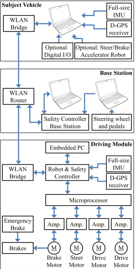
[image:2.595.316.549.146.610.2]pre-programmed trajectory without coordinating its movements with any other vehicles. Figure 1 shows the overall system layout with its respective nodes and peripheral equipment including the network architecture within and in-between each node.
Figure 1. System Architecture of the DCT
In the case of the VUTs movements being coordinated with the DCT, the VUT comprises the following components:
Notebook computer
Full-size inertial measurement unit (IMU) Differential GPS receiver
Wireless LAN Bridge
Optional: Steer/Brake/Accelerator-Robot Optional: Digital I/O board
WLAN
Bridge D-GPS
receiver Full-size IMU
WLAN Router
Safety Controller Base Station
WLAN
Bridge Robot & SafetyController
Amp. Amp. Amp.
Embedded PC
Brakes
Steer Motor Brake
Motor MotorDrive MotorDrive Amp.
Microprocessor
D-GPS receiver Full-size IMU
M M M
M Emergency
Brake
Optional: Steer/Brake/ Accelerator Robot Optional:
Digital I/O
Steering wheel and pedals Subject Vehicle
The VUT can either be driven by a human driver or can be set up to act as a semi- or fully autonomous, driverless vehicle. The latter requires specific robots to be fitted to the vehicle or a vehicle capable of drive-by-wire. In the case that the VUT is driven by a human, the notebook computer is used to set up the tests that should be performed, to monitor the test procedure and give (corrective) instructions to the driver. The IMU provides precise measurements of the acceleration as well as the rotational motion while the D-GPS signal is used to improve the positional accuracy of the VUT. The WLAN bridge transmits the measurements to the base station and DCT where, if necessary, it is used to adapt the driving strategy. The D-GPS signal can either be received from a local D-GPS base station or via mobile radio. The VUT can additionally be fitted with a digital I/O board that records or triggers discrete events such as an audible alert signalling the driver to perform a certain driving manoeuvre, ADAS warnings or open-loop steering/braking/accelerating manoeuvres. If the VUT is operated driverless, a remote connection to the VUT computer from the base station allows the configuration of the tests.
The base station serves as the central hub for all in- and outputs to and from the VUT and DCT. It is where the test engineer controls and supervises the movements of the vehicles. The base station is comprised of the following components:
Two notebook computers Steering wheel and pedals Wireless LAN Router Safety controller base station
One of two notebook computers establishes a remote connection to the DCT computer, thus allowing the operator to set up the tests for the DCT. The second notebook computer runs the software that allows the engineer to start and stop the previously selected tests remotely and allows the DCT to be driven manually via the steering wheel and pedals. The safety controller base station transmits a watchdog signal to the DCTs safety controller. If the watchdog signal is not received by the DCTs safety controller within the required time, the DCTs emergency protocol is activated which first activates the regular on-board braking system and, if it does not suffice, the emergency brake is fired bringing the DCT to a safe and quick stop.
Although a fully operational DCT consists of the DM, the SCTC and the SCT, only the DM has active components. The driving module comprises the following components: Two DC drive motors and amplifiers
One brushless DC steering motor and amplifier One brushless DC braking motor and amplifier Hydraulic disc brake with master brake cylinder Spring-loaded emergency brake system
Full-size inertial measurement unit (IMU) Differential GPS receiver
Wireless LAN Bridge Robot & Safety Controller
Microprocessor controlling the on-board CAN bus Embedded computer
The embedded computer runs the same software as the notebook computer in the VUT and is accessed remotely form the base station to set up the tests and monitor the DM. Information about the test to be performed is then loaded into the robot controller which in turn calculates the required drive motor torque, steering angle and brake level to fulfill the time-space trajectory of the test. The drive motor torque command, steering angle command and brake level command are transmitted via CAN bus to a microprocessor that actuates the corresponding components and also receives feedback from these components about their current status which is relayed back to the robot controller to achieve a closed-loop control. Identical to the VUT, the safety controller on the DM receives a watchdog signal from the base station and activates the emergency protocol if it is not received within a given timeframe. The D-GPS signal can again be received from a local base station or via mobile radio and increases the positional accuracy of the DM to up to 2 cm.
3. Dynamic Crash-Target
3.1. Driving Module (DM)
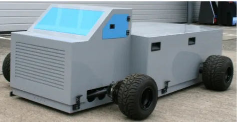
[image:3.595.313.551.454.577.2]The Driving Module (Figure 2) is the core element of the DCT as it is responsible for the reliable and precise guidance of the attached SCTC carrying the Soft Crash Target.
Figure 2. Driving module with enclosure
Each of the two DC motors drives one of the rear wheels as the DM features a split rear axle to allow for torque vectoring, increasing the DM’s manoeuvrability. Steering of the front wheels is achieved by a brushless DC servo motor. A set of disc brakes at the front wheels and both drive motors at the rear wheels provide enough braking performance in order to bring the DM to a quick and safe stop after a test scenario has been completed or to avoid reaching the collision area after disconnecting from the SCTC. The hydraulic brake system at the front wheels is actuated by means of a master brake cylinder. The master brake cylinder is either activated by the brushless DC brake motor or the spring-loaded emergency brake system. Both brake systems are connected to the master brake cylinder via a fixed linkage. They are not exclusive to each other and permanently run in parallel. The emergency brake however can at any time overpower the DM’s system brake. The system brake is actuated autonomously by the robot controller according to the space-time trajectory that has been set up and can also be activated manually by the operator using the brake pedal at the base station.
All components draw their power from two centrally placed battery packs in between the front and rear wheels of the kart chassis. The battery packs are easily accessed and exchanged reducing downtime to a minimum. The steering and brake motors as well as the emergency brake sit in front of the battery pack. The two drive motors as well as the robot and safety controller are mounted behind the battery pack. As a result the DM features a slightly tail-heavy weight distribution.
The DM has the SCTC attached to its front, rear or one of its sides by means of a magnetic spring-loaded coupling mechanism. To connect the DM and the SCTC, the coupling mechanism is pressed into a fitting on the SCTC where it is held in place by a permanent electromagnet. Once the decoupling event has been triggered, as per the pre-programmed trajectory, a current is applied to the magnet cancelling out the magnetic field. Due to the utilized spring, the coupling mechanism is pulled out of the fitting and the DM and SCTC are separated allowing the DM to leave the collision area.
3.2. Soft Crash Target Carrier (SCTC)
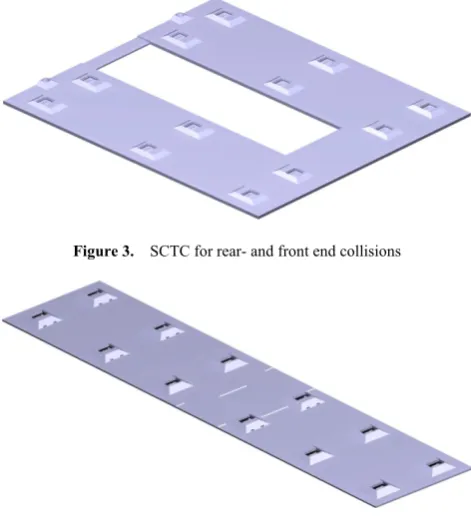
The Soft Crash Target Carrier features two identical flat platforms made from PVC (polyvinyl chloride) which are connected to each other via additional links. Each platform is fitted with six ball bearing mounted wheels. The wheels are connected to the platform through a spring steel wheel suspension. This allows the platform to hunker down when driven over by a VUT, reducing the load on the SCTC’s wheels by creating a direct load path from the VUT’s tyre to the ground. Under normal operating conditions the ground clearance is about 1 cm with the overrun height for the most part being equal to the material thickness of the platforms (1 cm) except for a small area around the six wheel assemblies.
To prevent any damage to the wheel assemblies due to the VUT driving over them, a small rugged enclosure made from PVC has been put in place around each wheel assembly. The enclosures are angled on each side to reduce the load into the suspension of the VUT even further. The overrun height in these areas increases to 3 cm.
[image:4.595.313.549.307.573.2]The platforms can easily be rearranged to suit different usage scenarios. For rear and front end scenarios the platforms are put next to each other, as seen in Figure. 3. An appropriate soft crash target for said scenarios is then mounted on the edge of the SCTC. For side crash scenarios the two platforms are mounted behind each other (Figure 4), resulting in a long, narrow SCTC allowing a full size side soft crash target to be fitted. Scenarios requiring a rear and side view of a soft crash target at the same time can be represented by combining the side configuration with parts of the rear configuration leading to an L-shaped platform structure.
Figure 3. SCTC for rear- and front end collisions
Figure 4. SCTC for side impact and sideswipes
Figure 5. Soft Crash Target Carrier (SCTC) V2
The construction of the SCTC V2 facilitates mounting, housing and protection for all the system components. These include a small single board computer, sensors, two brushless DC motors for the propulsion, one brushless linear DC motor for steering, batteries, power supplies and the steering system. A D-GPS receiver is used for precise positional control. The SCTC V2 is constructed from the same material as the previous version. The steering and the drive unit of the SCTC V2 are protected by angled PVC housings. While every effort has been made to keep the overrun height as low as possible, it nevertheless slightly increased to 5.3 cm to accommodate the additional components. However, tests have shown that the new height does not lead to any problems when run over by a standard height vehicle, i.e. the potential for contact between the structure of the vehicle under test (e.g. undercarriage or bumpers) and the SCTC V2 is still not existent. Similar to the non-steered and non-propelled version, the SCTC V2 employs a retractable wheel assembly that allows the structure to squat onto the road surface when driven over by the vehicle under test.
Similar to SCTC V1, the newly developed SCTC V2 is attached to the DM via a magnetic spring-loaded coupling mechanism. The DM is used to accelerate the SCTC V2 up to the desired target velocity of the scenario under consideration as well as keeping the velocity up to the beforehand calculated separation point. After separation from the DM, the actively guided SCTC takes over the velocity control according to the space-time trajectory and performs corrective steering measures. Also, the actively guided SCTC allows intersection scenarios with turning vehicles to be realized. The turning radius of the SCTC V2 has been designed in accordance with the German road traffic licensing regulation which defines that every car must have a turning radius of 12,5 m or less. The SCTC V2 has turning radius of 12 m in the side crash configuration and a turning radius of 10 m in the front- and read end configuration. The SCTC V2 is able to brake with up to 7 m/s². This is not achieved by additional mechanical brakes, but by using the already available brushless DC motors that are also used to propel the SCTC. Considering the air resistance of the side crash target (worst case scenario air
resistance wise) and the rolling resistance of the SCTC, around 9 kW need to be dissipated for an assumed braking manoeuvre starting at 60 km/h with a deceleration of 6 m/s². The needed braking power is well within the operating limits of the used brushless DC motors. Not needing additional mechanical brakes drastically simplifies the design of the SCTC V2.
3.3. Soft Crash Target (SCT)
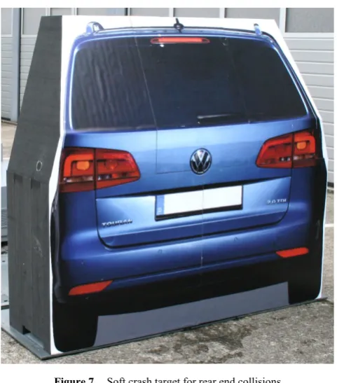
[image:5.595.312.550.293.399.2]The Soft Crash Target consists of several individual blocks of low density polyethylene (PE) foam which separate on impact to reduce stress on the VUT and the SCT itself. The blocks are interlocked among themselves and connected to the carrier by a tongue and groove mechanism (Figure 6) providing sufficient support for high velocity operations of the DCT.
Figure 6. Soft crash target side view with tongue and groove mechanism
Figure 7. Soft crash target for rear end collisions
[image:5.595.312.553.416.690.2]imprinting high quality images on a film attached to the individual blocks representing a certain view of a vehicle (rear, side, front or any combination of these), see Figure 7. Important features for the detection algorithms such as shadow underneath the imprinted vehicle as well as glossy wheel rims with a high contrast to the surrounding matt tyre have also been considered. To further improve the realism of the SCT, reflective stripes can be added on demand. The SCT is changed according to the driving scenario or function under test (e.g. crossing-paths, sideswipes, rear-end, front-end, convoy-driving, etc.). As has been outlined before, use cases requiring a side and rear view at the same time use an L-shaped Soft Crash Target. Due to the simple structure, the SCT can be reassembled by one person within two minutes. Depending on the number of collisions with the SCT as well as how hard the imprint on the SCT has been dragged on the ground after a collision, regular changes of the imprint might be necessary to ensure sufficient detection.
4. Method of Operation
4.1. Trajectory Planning
Before a test can be run, the appropriate space-time trajectories for the DCT and if applicable, the VUT have to be generated. The test runs can be reconstructed real world accident scenarios or hypothetical ones. In any case they need to be physics-based, i.e. the DCT and VUT have to be at certain waypoints with a certain velocity to fulfill the end condition (e.g. collision, near miss, beginning of the beam opening angle of a sensor, etc.) of the test run. The trajectories can have any shape, the DCT and VUT trajectory do not necessarily have to intersect and they can include variations in speed for both vehicles. Additionally, the trajectories also store information about discrete events that need to be triggered at specific waypoints along the trajectory. These can be messages to the driver of the VUT that a certain task is required (e.g. braking, steering), but also the point in time when the DM should disconnect from the SCTC is defined as such a discrete event.
4.2. Mode of Operations
The Dynamic Crash Target supports four different operating modes:
Hold Manual
Semi-Autonomous Fully-Autonomous
Whenever no tests are currently running, the DCT is in the hold mode. The hold mode keeps the DCT operational, i.e. positional, sensor and actuator data is still being transmitted to the base station although no test is currently running.
The manual mode allows the DCT to be remote controlled by an operator at the base station via steering wheel and
pedals for speed input. This mode is used for pre-positioning of the DCT prior to a test run so it can spline onto the pre-programmed trajectories and for returning the DCT to its origin or point of interest. It is also used for attaching the SCTC back to the DM after separation via the magnetic coupling as well as service and charging the batteries.
Within the Semi-Autonomous mode the operator controls the speed of the DCT by means of remote pedals while the path following is controlled autonomously. This mode is often used for splining onto the pre-programmed trajectory if the starting position is somewhere near the trajectory. It is also used to for bringing the DCT back to the starting position after a test run on a so called reverse trajectory that has been pre-programmed. Having a closed trajectory loop containing the test trajectory and the reverse trajectory allows for quick repetition of tests.
The Fully-Autonomous mode requires no input from the operator. The DCT is driven according to the speed and path information contained within the pre-programmed trajectory. The speed of the DCT is coordinated with the vehicle under test to allow the DCT, or more specifically the SCTC, to intersect at the required point of interest. Deviations in speed of the vehicle under test are taken into account and adjusted accordingly by corrective measures of the DCT. The operator can activate a sub-mode mid-test to deactivate speed corrective measures of the DCT to allow the DCT to pass through the point of interest at the speed contained within the trajectory, independent of the position or speed of the vehicle under test.
4.3. Testing with the DCT
After the initialisation procedures of the DCT have been completed, it is put into hold mode and connected to the SCTC. Once in hold mode, the previously created trajectory and selected test are downloaded onto the robot controller. For the DCT to travel along its path it needs to be within a certain start zone allowing it to spline onto the pre-defined trajectory. This is achieved by utilizing the manual control at the base station (steering wheel and pedals). The procedure for the VUT is quite similar. The DCT and, if applicable, VUT are then set to the Semi or Fully-Autonomous mode.
time-to-collision less than a threshold, ADAS warnings, separation command, etc.). The SCTC, being it the passive or actively guided version, continues to travel along the path up to the collision point or point of interest.
After a collision has taken place or the test run is finished, the SCT is reassembled (if needed) and the operator manually drives the DM near the SCTC so it can be reconnected for subsequent test runs. Afterwards the operator can either manually drive the DCT back to the start zone or use a pre-programmed reverse trajectory that is autonomously driven by the DCT. From this point on, the aforementioned process repeats.
4.4. Use Cases
[image:7.595.310.552.170.576.2]First and foremost, the DCT is used for the evaluation and validation of current and future ADAS. Application examples of some of the possible driving scenarios for current and future ADAS are shown in Figure 8.
Figure 8. Driving situations for current and future ADAS
Additionally, the usefulness of new sensor concepts and the combination of different sensor technologies via sensor fusion is another field of application. With the actively guided SCTC the DCT can furthermore be used for a preliminary performance assessment of ADAS in accordance with Euro NCAP (European New Car Assessment Program), NHTSA (National Highway Traffic Safety Administration) and IIHS (Insurance Institute for Highway Safety).
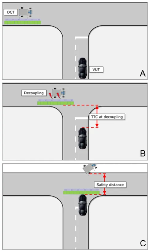
Figure 9 shows the process of a test with the DCT and a vehicle under test (VUT) for a cross traffic scenario.
Figure 9A shows the DCT and the VUT at their respective starting positions before the test of a cross traffic scenario. The Drive Module (DM) is attached to the Soft Crash Target Carrier (SCTC) in its side crash configuration and there is adequate distance between the VUT and DCT to allow for each of them to achieve their testing velocity according to the pre-programmed trajectory. Once the test starts, the VUT is driving towards the perpendicular to it moving DCT. At a pre-programmed trigger point, such as a certain time to collision (TTC), the DM detaches itself from the SCTC by releasing the magnetic coupling, see Figure 9B. The DM then starts evasive maneuvers to leave the possible harmful
collision area whereas the SCTC and VUT continue to travel forward. Depending on the system under test in the VUT and its functionality, a collision between the VUT and SCTC may take place or may be avoided. In any case, the DM with its costly and sensitive measurement equipment is far enough away from the collision area and no harm can be inflicted to either test personnel or equipment, see Figure 9C.
Figure 9. Process of testing with the DCT in a cross traffic scenario
[image:7.595.60.296.319.452.2]acceleration of the following vehicle occurs.
[image:8.595.312.552.112.352.2]The driver of the following vehicle has to react to the increasingly more critical becoming situation either by braking or performing an evasive maneuver. If the driver does not react at all, not quick or not sufficient enough, the situation quickly becomes uncontrollable, likely leading to a collision with the vehicle in front. Making use of the DCT as the second vehicle actually allows a collision to happen whereas intervening action, either by a safety concept or a co-driver, has to be taken in case of a real vehicle. Performing experimental studies with a large number of normally practiced drivers or a small sample of expert drivers varying the erroneous acceleration, can yield the controllability of said driving scenario. Using the collision velocity as a measure and correlating it with known accident severity at certain speeds, the severity of the aforementioned driving scenario can also be determined.
Figure 10. Example for a controllability study: Erroneous acceleration of the following vehicle
5. Summary and Conclusions
The developed Dynamic Crash Target (DCT) allows the assessment, evaluation and validation of current and future ADAS with minimal risk to the test personal and vehicles involved. It does so by utilizing a three-part structure consisting of a Driving Module, a Soft Crash Target Carrier and a Soft Crash Target that is suitable for the driving scenario and system under test. The DCT can be driven manually or fully autonomous utilizing a pre-programmed space-time-trajectory. The vehicle under test can be driven by a human driver or semi-/fully autonomous by means of respective driving robots or drive-by-wire. The DM disconnects from the SCTC just moments before a collision or a near miss is imminent and thus the sensitive and expensive measurement equipment is never at risk. For driving scenarios that require high positional accuracy and driving performance, an actively guided SCTC (V2) has been developed. The low overrun height of both the SCTC V1 and SCTC V2 allows running over it in a braked or unbraked condition without any damage to the VUT or the SCTC even at high velocities. In addition to the test of current and future ADAS, the DCT can also be used in controllability studies for homologation purposes according to ISO 26262.
[image:8.595.60.296.297.347.2]Appendix
Table 1. Performance Specification of the DCT Longitudinal acceleration (with
SCTC and SCT) +0.4g
Longitudinal deceleration under braking
(without SCTC and SCT) -0.8g Lateral acceleration
(with SCTC and SCT) ±0.4g DM top speed (alone) > 100 km/h
DCT top speed
(with SCTC and SCT) 80 km/h SCTC top speed
(actively propelled version) 65 km/h D-GPS positional accuracy 2 cm
Drive motor performance Two DC drive motors, totalling: 30 kW peak 9,5 kW continuous
Bus voltage 48 VCD
Turning radius
(without torque vectoring) < 6 m Battery charge time 60 min (full charge) Battery switch time 5 min SCT reassembly time 2 min
REFERENCES
[1] Pawellek, T., Henze, R.Küçükay, F. (2014). Testing and Optimization of ADAS for Longitudinal Guidance (ACC, AEB). International Conference – The Road to Automated Drive 2014. 30 June – 2 July. Stuttgart, Germany.
[2] Sandner, V. (2013). Development of a test target for AEB systems: development process of a device to test AEB systems for consumer tests. Proceedings of the 23rd International Technical Conference on the Enhanced Safety Vehicles (ESV). 27 May – 30 May. Soeul, South Korea. [3] Gietelink, O., Ploeg, J., De Schutter, B. Verhaegen, M. (2004).
VEHIL: A test facility for validation of fault management systems for advanced driver assistance systems. Proceedings of the 4th IFAC Symposium on Advances in Automotive Control. 19 – 23 April. Salerno, Italy.
[4] Hoffmann, J. (2008). Das Darmstädter Verfahren (EVITA) zum Testen und Bewerten von Frontalkollisions- gegenmaßnahmen. Fachgebiet Fahrzeugtechnik, TU Darmstadt, Dissertation.
[5] AEDesign (2015). AVCASS – Autonomous Vehicle for the Certification of Active Safety Systems. Available from: <http://www.aedesign.com.pk/AVCASS large.html>. [15.01.2015].
[6] Anthony Best Dynamics (2014). Guided Soft Target Vehicle. Outline Specification SP6011 – Issue 4. <http://www.abd.uk.com> [August 2014]