i
LIGHT SOLIDIFICATION OF KUALA PERLIS DREDGED MARINE SOIL VIA ADMIXTURES OF GGBS – CEMENT AND SAND:
1-D COMPRESSIBILITY STUDY
SUAATHI A/P KALIANNAN
A thesis submitted in
fulfillment of the requirement for the award of the Degree of Master of Engineering Technology
Faculty of Engineering Technology Universiti Tun Hussein Onn Malaysia
iii
DEDICATION
iv
ACKNOWLEDMENT
Firstly, I would like to express my deepest gratitude and appreciation to my supervisor, Assoc. Prof. Dr. Chan Chee Ming. Her guidance, encouragements, and understanding have truly provided a good foundation for this research. All the comments and suggestions given has help me in completing this research with excellence.
I am grateful to my beloved family members. I thank Lord, my father, mother and brother, who unceasingly providing all my needs, giving me their full support, care and love. Their encouragement and motivation had driven me to complete this work with more confidence and determination.
Besides, I would like to thank all my colleagues and RECESS technicians who have given me their cooperation in assisting me to complete the work. Their willingness in giving out their time and effort is highly appreciated.
All in all, this research project would not have been successfully completed without the help of all these parties and also the previous researchers whom have been acknowledged within the reference section.
v
ABSTRACT
vi
ABSTRAK
vii
CONTENT
TITLE i
DECLARATION ii
DEDICATION iii
ACKNOWLEDGEMENT iv
ABSTRACT v
CONTENTS vii
LIST OF TABLES xii
LIST OF FIGURES xiii
LIST OF SYMBOLS xvii
CHAPTER 1 INTRODUCTION
1.1 Research Background 1
1.2 Problem Statement 2
1.3 Research Objectives 5
1.4 Scope of Research 4
1.5 Significance of Research 4
1.6 Organisation of Thesis 5
CHAPTER 2 LITERATURE REVIEW
2.1 Introduction 6
2.2 Dredging 6
2.3 Types of Dredging Equipment 7
2.4 The Dredging Process 10
viii
2.6 Dredged Marine Soil (DMS) 13
2.7 DMS Management Framework 15
2.8 Development of DMS Management Framework 21 2.8.1 Basic steps in planning process 22 2.9 Preliminary DMS Management Framework 24
2.9.1 Transportation 26
2.9.2 Storage 28
2.9.3 Treatment 28
2.10 Beneficial Use of DMS 30
2.11 Solidification of DMS 31
2.12 Types of Solidifying Agent
2.12.1 Cement 31
2.12.2 Ground Granulated Blast Furnace Slag 34
2.12.3 Sand 35
2.13 Consolidation 37
2.14 Consolidation Parameters
2.14.1 Coefficient of consolidation (Cv) 38
2.14.2 Coefficient of volume compressibility (mv) 39
2.14.3 Permeability 40
CHAPTER 3 METHODOLOGY
3.1 Introduction 42
ix
3.3 Soil Sampling 44
3.3.1 Storage of Samples 44
3.4 Soil Classification 45
3.4.1 Moisture Content of Soil 44
3.4.2 Liquid Limit – Cone Penetration Method 46
3.4.3 Plastic Limit 46
3.4.4 Specific gravity 47
3.4.5 Dry Sieving Test 48
3.4.6 Sedimentation By The Hydrometer Method 48
3.4.7 Wet Sieving Test 49
3.4.8 X-Ray Fluorescence (XRF) Analysis 49 3.4.9 Loss on Ignition (LOI) 50
3.5 Preparation of Solidified Agents 52
3.6 Curing period 53
3.7 Test Specimen Details 53
3.8 One -Dimensional Consolidation Test 56
3.8.1 Preparation of Specimens 56
3.9 Typical plot of settlement curve 58
3.10 Physical and Chemical Properties 61
3.10.1 X-ray fluorescence (XRF) Analysis results 63
CHAPTER 4 DATA ANALYSIS AND DISCUSSION
x
4.2 Analysis of t50 and t90 64
4.3 Comparison of Compression Curves for Binders 67
4.4 Cement ratio effect 71
4.5 Compression curves for sand admixed DMS 72 4.6 Compression curves for binder + sand admixed DMS 74 4.7 Coefficient of volume compressibility (mv)
of DMS + Binders 76
4.8 Coefficient of consolidation (cv) of DMS + Binders 79
4.9 Coefficient of permeability (k) of DMS + Binders 81 4.10 Coefficient of volume compressibility (mv)
of DMS + Sand 83
4.11 Coefficient of consolidation (cv) of DMS + Sand 84
4.12 Coefficient of permeability (k) of DMS + Sand 86 4.13 Coefficient of volume compressibility (mv),
consolidation (Cv) and permeability (k) of
DMS + Binder + Sand 87
4.14 Relationship of coefficient of volume of
compressibility (mv) and Constrained modulus (Mo) 90
4.15 End of Primary Consolidation Time, teop of
DMS + Binders 96
xi
4.18 Relationship of k, mv and cv with e 104
4.19 Relationship of mv, cv and k 107
CHAPTER 5 CONCLUSIONS AND RECOMMENDATIONS 5.1 Introduction 110
5.2 Conclusions 110
5.2.1 Summarised Main Findings 111
5.3 Overall Conclusions 113
5.4 Recommendations 113
REFERENCES 114
xii
LIST OF TABLES
2.1 Types of dredgers (Bray & Cohen, 2010 and Vlasbom,2003) 7 2.2 Available criteria of dredging related rules in Malaysia 11 2.3 Comparisons of problems of dredging faced internationally 12
2.4 Definition of DMS (Owens, 2008) 13
2.5 Particle size distribution of DMS 14
2.6 Importance of Transportation 16
2.7 Importance of Storage 18
2.8 Importance of Treatment 19
2.9 Typical value of coefficient of consolidation 39 2.10 Typical value of coefficient of volume compressibility 40 2.11 Typical values of coefficient of permeability 41 3.1 Categories of clay according to value of liquid limit (Head, 1992) 46
3.2 Test specimen for binders + DMS 55
3.3 Test specimen for sand + DMS 55
3.4 Test specimen for binders + sand 55
3.5 Soil Classification 56
3.6 The XRF results for DMS at Kuala Perlis. 63
4.1 Compression Index (Cc) of DMS + Binders 67
xiii
LIST OF FIGURES
1.1 Ports in Malaysia (www.searates.com/maritime/malaysia, 2015) 1 1.2 Figure 1.2: Kuala Perlis jetty area (Souce: Google earth,
coordinate: 6° 24' 0" North, 100° 8' 0" East) 3 2.1 Basic steps in planning process (National Dredging Team, 1998) 21 2.2 Adaptation of Basic steps in planning process 23 2.3 DMS Management Framework for Artificial Land Creation 25 2.4 Pipelines (Source: www.usace.army.mil, 2012). 27 2.5 Barges (Source: www.norfolkdredging.com, 2012) 27 2.6 Hopper Dredger (Source: Kuala Perlis, 2014) 27 2.7 Truck (Source: www.aliexpress.com, 2014) 27 2.8 Conveyor belt (Source: http://www.multipino.com, 2013) 27
2.9 Ordinary Portland cement 33
2.10 Ground granulated blast furnace slag (GGBS) 34
2.11 Sand 36
2.12 Changes of fabric in the clay-sand mixture 36
3.1 Methodology flowchart 43
3.2 Clamshell Dredger (Source: Kuala Perlis dredging site, 2014) 44 3.3 The DMS were stored in the covered container 44
[image:12.595.112.488.247.753.2]xiv
3.5 Vacuum desiccators with protective cage 48
3.6 Schematic diagram of XRF Analysis (Verma, 2007) 50
3.7 Bruker S4 Pioneer 50
3.8 LOI test 51
3.9 Materials used as a solidifying agent 52
3.10 Procedure of Oedometer test 57
3.11 Settlement plot for 7C3G_10% at stress of 800 kPa 59 3.12 Settlement plot for 3C7G_20% at stress of 800 kPa 60 3.13 Particle size distribution of DMS and Sand 62 4.1 Settlement plot for 7C3G_30% at 12.5kpa 65 4.2 Settlement plot for 1C0G_20 % at 12.5kpa 66
4.3 Compression curves for 10 % binders 68
4.4 Compression curves for 20 % binders 69
4.5 Compression curves for 30 % binders 69
4.6 Compression curves for 3C7G of 10, 20 and 30 % binder 70
4.7 Cement dosage in the binder 71
4.8 Compression curves for Sand admixed DMS 73
xv
4.14 Coefficient of consolidation in DMS + Binder (10 %) 80 4.15 Coefficient of consolidation in DMS + Binder (20 %) 80 4.16 Coefficient of consolidation in DMS + Binder (30 %) 81 4.17 Coefficient of permeability in DMS + Binder (10 %) 82 4.18 Coefficient of permeability in DMS + Binder (20 %) 82 4.19 Coefficient of permeability in DMS + Binder (30 %) 83 4.20 Coefficient of volume compressibility in DMS + Sand 84 4.21 Coefficient of consolidation in DMS + Sand 85 4.22 Coefficient of Permeability in DMS + Sand 86 4.23 Coefficient of volume compressibility in DMS + Binder + Sand 88 4.24 Coefficient of consolidation in DMS + Binder + Sand 89 4.25 Coefficient of Permeability in DMS + Binder + Sand 89 4.26 Relationship of mv and Mo with σv' (DMS+binder 10%) 91
4.27 Relationship of mv and Mo with σv' (DMS+binder 20%) 92
4.28 Relationship of mv and Mo with σv' (DMS+binder 30%) 93
4.29 Relationship of mv and Mo with σv' (DMS+sand) 94
4.30 Relationship of mv and Mo with σv' (DMS+binder+sand) 95
xvi
4.35 End of primary consolidation time in DMS + Sand (FS) 100
4.36 Permeability of comparable specimens 102
4.37 Volume compressibility curves of comparable specimens 103
4.38 Clay-sand model 103
4.39 Process of clay particles sealing the sand 104 4.40 Relationship of permeability with void ratio of DMS+binder+sand 105 4.41 Relationship of volume compressibility with void ratio
of DMS+binder+sand 106
4.42 Relationship of coefficient of consolidation with void ratio of
DMS+binder+sand 107
4.43 (a) Plot of volume compressibility with permeability for
DMS+binder+sand 108
4.43 (b) Plot of volume compressibility with permeability for
DMS 108
4.44 (a) Plot of coefficient of consolidation with permeability for
DMS+binder+sand 109
4.44 (b) Plot of coefficient of consolidation with permeability for
xvii
LIST OF SYMBOLS AND ABBREVIATIONS
C - cement
C2S - Dicalcium silicate
C2SHx, C3S2Hx - hydrated calcium silicates
C3A - Tricalcium aluminate
C3AHx, C4AHx - hydrated calcium aluminates
C3S - Tricalcium silicate
C4AF - Tetracalcium alumino-ferrite
Ca(OH)2 - hydrated lime
Ca2+ - Calcium ion
CaO - Calcium Oxide
CO2 - Carbon dioxide
cv - coefficient of consolidation
DMS - Dredged marine sediments
e - void ratio
e.g. - for example
Fe2O3
Gs
- -
Iron Oxide Specific gravity
xviii
i.e. - in other words
K+ - Potassium ion
K2O - Potassium Oxide
k - Permeability
m - meter
Mg2+ - Magnesium Oxide
MgO - Magnesium Oxide
mm - milimeter
mv - coefficient of volume compressibility
Mo - Constrained modulus
Na2O - Sodium Oxide
NCL - normal consolidation line OPC - Ordinary Portland cement RECESS - Research Centre for Soft Soils
SiO2 - Silica
SO3 - Sulphur Trioxide
SO42+ - Sulfate ion
t - tonne
teop - End of primary consolidation time
xix
w - moisture content
Ws - dry weight
Ww - wet weight
XRF - X-ray Fluorescence
ε - Vertical strain
- density
CHAPTER 1
INTRODUCTION
1.1 Research Background
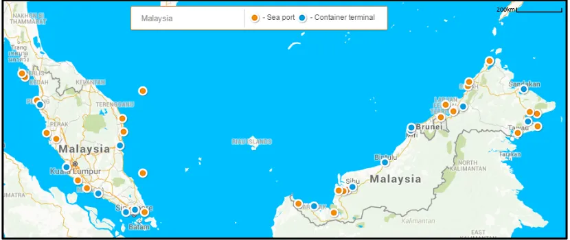
[image:19.595.114.529.459.634.2]Malaysia has 10 major ports and 59 minor ports to cater for commercial purposes as it is surrounded by international waters and strategically located along the primary shipping routes (Khalid, 2006).
Figure 1.1: Ports in Malaysia (www.searates.com/maritime/malaysia, 2015)
To maintain the waterways, dredging has to be carried out. 4 million m3 of sediments for maintenance dredging of ports and jetties are dislodged in the year 2013 (Chan, 2014). Significant quantities of dredged marine soil (DMS) have been
2
generated from the maintenance of channels depth, anchorages and for harbour development.
Disposing large quantities of dredged materials is often one of the greatest challenges faced in a dredging project. When these materials are treated as a waste, the selection of disposal destination often becomes controversial (International Association of Dredging Companies, IADC, 2009). This is because pollution and health risk can be caused if disposed either in land and water. In the case of Malaysia, the normal practice is to dispose the dredged materials in allocated offshore dumping sites.
However, the benefits of the dredging project can be enhanced through the use or re-use of the dredged material for a beneficial purpose (International Association of Dredging Companies, IADC, 2008 and Stollenwerk et al., 2012). In recent years, many researchers have demonstrated that these materials have added value and are not wastes (e.g. Makusa, 2012; Azhar et al., 2014; Chan et al., 2012). Efforts in finding uses, application for these materials and for coordinating the supply of these materials with a concurrent demand are now growing. These includes the construction of Haneda airport, Japan (International Association of Dredging Companies, IADC, 2009), land reclamation works in Chek lap kok Airport of Hong Kong and Arabian gulf off the coast Dubai (Randall et al., 2011). Some of the potential reuse options include beach replenishment with sand, use in buildings or coastal works and land reclamation (Cronin et al., 2006). Thus, this geo-waste should be reused as a soil for civil works.
1.2 Problem Statement
3
[image:21.595.115.528.380.570.2]Kuala Perlis jetty terminal is an attraction point for tourist as it is one of the main route to Langkawi. In order to maintain the waterway depth for the passerby ships, maintenance dredging is being done once a year. Once dredging is done, the DMS is being dumped in a permissible distance from the shore and pollutes the sea. Thus, this geowaste could be regenerated as a new resource to substitute soil for civil works such as for embankment and land reclamation. The geowaste usually clay, silt or sand, Clay is referred to as a cohesive soil which includes clayey silt, sandy clay, silty clay and organic clay. This type of soil has low strength and high compressibility. Compressibility of soils is an important engineering consideration. This is due to the fact that soils subjected to increased effective stress would decrease in volume hence resulting in surface settlement (Schroeder et al., 2004). Thus, the addition of cement or other binder and granular materials could improve the weak soil with reduced settlement. Therefore, this shows that solidification of this geowaste could be a beneficial reuse for application in land reclamation.
4
1.3 Research Objectives
The aim of this research is to examine the compressibility behaviour and relationship between the consolidation parameters of DMS for beneficial reuse purposes. The objectives to be achieved are:-
i. To determine 1-D compressibility characteristics of lightly solidified DMS from Kuala Perlis using GGBS-cement and sand admixtures.
ii. To identify the improved settlement and consolidation rate of the solidified DMS as mentioned in objective i.
iii. To establish the relationship between the 1-D compressibility parameters.
1.4 Scope of Research
The main test conducted was 1-Dimensional oedometer consolidation test. In order to solidify the soil, binding agents and a type granular material were used. They were cement, ground granulated blast furnace slag and sand. These materials were chosen because they are readily available in Malaysia. The test was conducted to identify the compressibility behaviour, rate of settlement with the time and also the relationship between the consolidation parameters. The soil sample was collected at Kuala Perlis. The entire laboratory test programs were conducted in Geotechnical Engineering Laboratory, Environmental Laboratory, Environmental Analytical Laboratory, and RECESS facilities. All the results were analyzed according to the relevant standard and specification.
1.5 Significance of Research
5
(Murray et al., 2008). Waste and pollution can be reduced and new productive way of reusing DMS can be created.
1.6 Organization of Thesis
Chapter 1: Introduction
This chapter discusses the background of this research, current situation and problem statement of the study. There are also objectives, scope and its significance of
research.
Chapter 2: Literature Review
This chapter discusses the elaboration, information and previous studies by other researchers which are related to this study. It contains important information of the sources. It gives a new interpretation of old material or combine new with old interpretations mainly about reusing dredged marine soil and guidelines to manage the dredged material after retrieval.
Chapter 3: Methodology
This chapter illustrates the flow and method of research starting from planning to implementations that have been carried out as well as related standards and guidelines on the laboratory works.
Chapter 4: Result Analysis
This chapter contains the overall result of this study. All the results obtained were discussed and analysed to show the new discovery of the research.
Chapter 5: Conclusions and Recommendations
Pag
6
CHAPTER 2
LITERATURE REVIEW
2.1 Introduction
Dredging is the relocation of underwater sediments and soils for the construction and maintenance of waterways, harbours and ports. Excavation, transport and disposal of sediments are the three main stages of dredging activities (Manap and Voulvolis, 2015). Dredging activities generates large volume of dredged marine sediment (DMS). DMS can be a valuable resource although most of it currently being disposed back into the sea due to economic, logistic and environmental constraints (CEDA, 2010).
2.2 Dredging
7
dredging is the dredging carried out in a new location and materials that has never been dredged out. Maintenance dredging is conducted where channels or constructions works has to be at their desired dimensions with a time frame (USACE, 2004) whereas remedial dredging is done to improve the quality, human health and environmental protection purposes (Bray and Cohen, 2010).
2.3 Types of dredging equipment
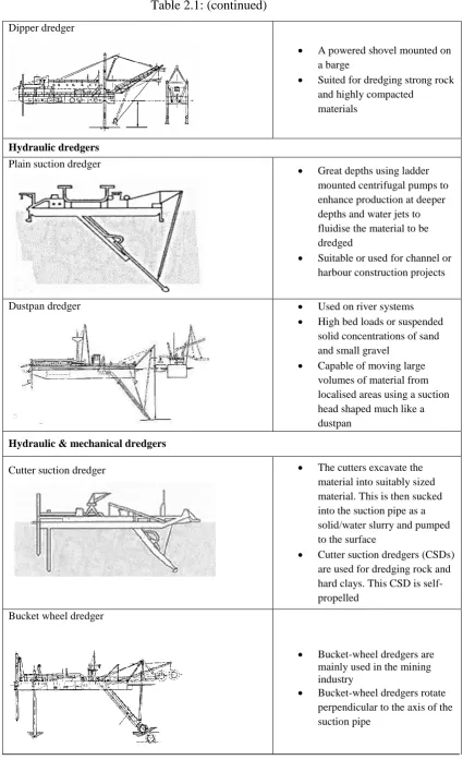
[image:25.595.109.534.444.760.2]There are few categories for describing types of dredgers. The types of dredgers are described by four classifications which are Mechanical dredgers, hydraulic dredgers, mechanical/hydraulic dredgers and hydrodynamic dredgers referring to Table 2.1. Production rates for dredgers vary widely depending on the circumstances, the material to be dredged and the transport and disposal methods applied. Other factors, such as weather and sea state, ship traffic, depth and thickness of material being removed, also affect dredging production rates (IADC, 2010).
Table 2.1 : Types of dredgers (Bray and Cohen, 2010 and Vlasbom, 2003)
Types of dredgers Description
Mechanical dredger
Grab/Clamshell dredger
Clamshell dredgers can be used in sands, some types of clay, gravel, cobbles and occasionally broken rock Dredge in fairly deep waters
and able to do precise spot dredging
Backhoe dredger
Barge-mounted for dredging, generally non-self-propelled and can have a moderate production rate
Hydraulically operated rams for movement, positioning and excavating
8
Table 2.1: (continued) Dipper dredger
A powered shovel mounted on a barge
Suited for dredging strong rock and highly compacted
materials
Hydraulic dredgers Plain suction dredger
Great depths using ladder mounted centrifugal pumps to enhance production at deeper depths and water jets to fluidise the material to be dredged
Suitable or used for channel or harbour construction projects
Dustpan dredger Used on river systems
High bed loads or suspended solid concentrations of sand and small gravel
Capable of moving large volumes of material from localised areas using a suction head shaped much like a dustpan
Hydraulic & mechanical dredgers
Cutter suction dredger The cutters excavate the
material into suitably sized material. This is then sucked into the suction pipe as a solid/water slurry and pumped to the surface
Cutter suction dredgers (CSDs) are used for dredging rock and hard clays. This CSD is self-propelled
Bucket wheel dredger
Bucket-wheel dredgers are mainly used in the mining industry
[image:26.595.106.532.74.772.2]9
Table 2.1: (continued)
Trailing suction hopper dredger Self-propelled ships with
hoppers or dredged material storage internal to the hull They dredge whilst underway,
travelling at low speeds. Flexible in terms of the
material to be dredged, placement alternatives, and the ability to work in protected and unprotected waters
Hydrodynamic dredgers
Water injection dredger
For maintenance dredging Uses water pressure to fluidise
the bottom material to be removed, creating dense fluid slurry
[image:27.595.109.534.73.478.2]10
2.4 The Dredging Process
The dredging process consists of the following four elements (USEPA, 2012 Vlasblom, 2003, Eisma, 2005 & PIANC, 2002):-
i) Excavation
This process involves the removal of sediments which consist of soils and rocks from the water body. A dredger is normally used to excavate the material either mechanically, hydraulically or by combination of both (see Table 2.1).
ii) Transportation of excavated materials
This process is about transporting the dredged materials to a storage area or disposal site. There are 2 types of transportation which are via water and land. It is generally achieved by one of the following methods:- - Self-contained hopper dredger
- Barges - Pipelines - Trucks
- Conveyor belt iii) Storage
Storage comes before the treatment process. Dredged materials can be stored for disposal or reuse but depends on quantity and the place of storage.
iv) Reuse or disposal of dredged materials
11
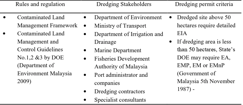
Table 2.2: Available criteria of dredging related rules in Malaysia
Rules and regulation Dredging Stakeholders Dredging permit criteria
Contaminated Land Management Framework Contaminated Land
Management and Control Guidelines No.1,2 &3 by DOE (Department of Environment Malaysia 2009)
Department of Environment Ministry of Transport Department of Irrigation and
Drainage
Marine Department Fisheries Development
Authority of Malaysia Port administrator and
companies
Dredging contractors Specialist consultants
Dredged site above 50 hectares require detailed EIA
If dredging area is less than 50 hectares, State’s DOE may require EA, EMP, EM or EMnP (Government of Malaysia 5th November 1987) -
2.5 Problems related to dredging
The cost of dredging varies according to the technology and equipment used, estimated volume, type of dredged material, distance from excavation to disposal site, time and distance of mobilization and demobilization, and disposal method. The high cost has always been the main problem for port operators, who are responsible for dredging and maintaining deep channels, but also need to spend funds to expand or build new terminals in order to cater for growing trade activities (Anderson and Barkdoll, 2010; Williams, 2008). Table 2.3 shows the comparison of problems faced
Table 2.3 Comparisons of problems of dredging faced internationaly (Manap, 2013)
Criteria The US The UK France Malaysia
Dredging problems
Economic and environmental problems:
- Trends in the shipping industry toward larger vessels requiring deeper draughts
- The result of years of dismissing environmental problems as irrelevant
- High cost of sediment remediation
Managerial problem:
-Confliction between stakeholders from federal, state and local political leadership during dredging
Environmental problem: - Loss of natural habitat
- The deteriorating water quality - Polluted dredged material - Beneficial use of dredged material
- Conflicts on defining what constitutes waste to describe dredged sediments
Managerial problem: - Potential friction between EU Directives and international conventions
- Other Directives on environmental protection, including Habitats and Birds Directives and Waste Framework Directive, lead to delays or cancellation of projects and to increase costs
Environmental problem: - Harbour sites are located in sheltered zones where tides, streams, swell, and wind cause the trapping of sediments that becomes an obstacle for the access of ships to the harbour infrastructures .
Social problem:
- Dredging involves many stakeholders including the community and each stakeholder has a view and some interests can diverge
- The late involvement of environmental protection is responsible for blockings, loss of money and loss of time
- No public inquiry procedure while applications are being considered
Social and economic problem: - Public participation
- Economic vs the Environment
Managerial and environmental problem: - Conflict of power distribution (State vs Federal) that cause delays
- No mandatory action for monitoring - No incentives for mitigation measures - Difficult to enforce EIA 1987 Order - Lack of cumulative impact analysis - Illegal sand dredging - Environment aspect was not included during pre-planning stage
13
2.6 Dredged Marine Soil (DMS)
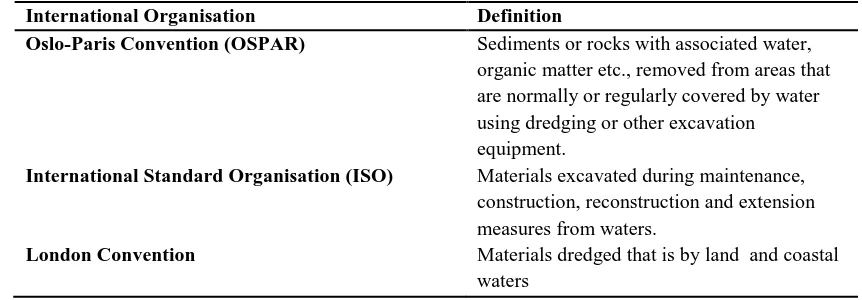
[image:33.595.101.532.288.438.2]Dredging can be described as underwater excavation of soils. It is necessary to maintain existing waterways, ports and water channels. The need of increase in waterway depths might be due to the increased demand for transporting people, equipment, materials and commodities by water. Besides that, dredging process is also used in flood control measures to maintain or improve the river or channels flow capacities. Table 2.4 shows some of the international definition of DMS.
Table 2.4: Definition of DMS (Owens, 2008)
International Organisation Definition
Oslo-Paris Convention (OSPAR) Sediments or rocks with associated water,
organic matter etc., removed from areas that are normally or regularly covered by water using dredging or other excavation equipment.
International Standard Organisation (ISO) Materials excavated during maintenance,
construction, reconstruction and extension measures from waters.
London Convention Materials dredged that is by land and coastal
waters
The soil excavated from the waterways, whether from the sea, river or port is known as dredged soil. Mostly, such dredged materials consist of sands, silts, clay and other material from underwater (Table 2.5). In Malaysia, the dredged soils have yet to be recycled and reused, but mainly disposed in designated open water, upland or onshore. However, for soils which contain contaminants, the placement options should be considered in terms of environmental sensitivity and responsibility (IADC, 2012).
14
[image:34.595.110.529.256.375.2]the wet soil to dry and stiffen it chemically. The use of improved soil (a mixture of dredged soil and converter slag) for land reclamation was practised in Japan (Matsumoto et al., 2014). Besides, treated soil has also been used for land reclamation in the Central Japan International Port and in the Port of Brisbane, Australia (Ganesalingam et al., 2011). This is an example of evidence that dredged materials can be treated to improve its suitability, either by improving its environmental properties or providing economic benefits (IADC, 2012).
Table 2.5: Particle size distribution of DMS
Reference Dredged Area Clay Silt Sand
Azhar et al., 2014 Marina, Melaka 59 % 16 % 20 %
Azhar et al., 2014 Tok Bali, Kelantan 75 % 19 % 4 %
Ganesalingam et al., 2011 Port of Brisbane 41% 38 % 5 %
Vinothkumar and Arumairaj,
2013 Coimbatore, India 56.68 % 14.17 % 29.15 %
Wang et al., 2013 Dunkirk Harbour,
15
2.7 DMS Management Framework
20 Table 2.6 Importance of Transportation
Mode of transportation
Advantages Disadvantages Comments References
Pipelines Less impact to
surrounding infrastructure and environment More cost effective both hydraulic and
mechanical dredging approaches
Closed circuit system
Leakage if not connected properly
Pipelines are the most reliable mode of
transportation to be used for direct usage or disposal of DMS. It can transport the DMS easily without polluting the environment and also any
infrastructures. While transporting process is going on, it will not disturb any passerby ships.
Erftemeijer & Lewis, 2006 Eisma, 2005 Vlasblom, 2003 IADC, 2014 USEPA, 2012 PIANC, 2002
Barges Self-
unloading
Used when need to be discharged within the water body
Equipped with doors or valves
Can be used with mechanical dredges
Can be unloaded in sea only
Stationary Risk of spillage
Barges are an open container to fill the DMS by using mechanical dredge equipment to lift the DMS from the water and place it into the barge. As for the self- unloading it can be only used for disposal but for non self –unloading barge, it can be towed by boat or ship to the shore and then transfer it to a truck to store it for reusing purpose.
Vlasblom,2003 Eisma,2005 USEPA,2012 PIANC,2002 Non self- unloading
Can be unloaded in sea or land
Can be used with mechanical dredges
20
Hopper dredges Can move about freely
Can dredge any kind of material
Can work in any calm or turbulent water Can work in both deep
or shallow areas
Not particularly suited to removing thin layers of (contaminated) sediment.
Hopper dredger is involved since the dredging process itself and is attached pumps to suck the DMS and is not dependent to the anchor and can move about. So after dredging, this dredger can move to the disposal site to dump the DMS or if to reuse the DMS, it can be transported using pipelines. Cutterhead dredger and other hydraulic dredges has the same function
IADC, 2014 Vlasblom, 2003 USEPA, 2012
Truck Loaded mechanically at
any density
Destination is flexible
Need more trucks considering the amount of DMS Spillage Noise
Truck is the road transport to move DMS from after collecting from the water to the storage or landfill and so on.
Eisma, 2005 Hayes, 2004 USEPA, 2012
Conveyor belt Continuously able to
transfer large amount Environmental effect is
quite low
High cost Fixed alignment
This method is least used because of the high cost and not really flexible. In most cases, material dredged mechanically will be assist by this conveyor belt
20 Table 2.7 Importance of Storage
Mode of Storage Description Comments References
Temporary Storage
Less than a year
Quantity of DMS to be stored must not exceed the quantity of material that can managed at the site. Minimise the amount of material
returned by spillage, erosion or other discharged to waters of the state.
Can be stored for reusing depends on when and where.
Storage area has been minimized as it takes up space and a lot of cost. Thus application for beneficial reuse is done for example: after dredging , while its being transported through pipeline, there’s a treatment plant build so that the DMS will be treated and straight away being transferred to onsite applications . It will be cost effective if it is a mega project.
Stollenwerk et al., 2012 USACE,2009
Welp et al., 2002 HTAC, 2007
Long-term Storage
More than one year, constitutes disposal
Must be located entirely above the high water table.
20 Table 2.8 Importance of Treatment
Method Description Advantages Disadvantages References
Preloading Conventional
preloading Placement of load prior to the real construction load in order to drain the water out vertically
Basic dewatering process slower Stapelfeldt, 2006
Das, 2011
Vacuum preloading
Surcharge load is replace by atmospheric pressure. This is to accelerate the consolidation. Horizontal drains are connected to a vacuum pump
no extra fill material construction time shorter environment friendly no risk of slope instability
Might have leakage
Stapelfeldt, 2006 Chai, 2005
Vertical drain Sand drain Filling sand into a hole in the soft ground
Accelerates consolidation Shorten the length of the
drainage path (spacing) Accelerate the dissipation of pore water pressure
Indraratna, 2000 Stapelfeldt, 2006 Das, 2008 Fabric encased
sand drain
Sand filling in a filter jacket
Prefabricated vertical drain
Synthetic filter jacket surrounding a plastic core
Sand compaction
Compacted sand/gravel column
Geotextiles Flexible textile fabrics of
controlled permeability used to provide filtration, separation or reinforcement in soil, rock and waste material.
Kamble Zunjarrao B, 2014 Tack.WY, 2007
Morgan et al., 2009 Schaefer et al., 1997
Stabilisation Mechanical
stabilisation
Altering the physical nature of native soil by either vibration or
20 compaction or by incorporating
other physical properties such as barriers and nailing
Makusa, 2012
Chemical
stabilisation Stabilised with cementitious materials (cement, lime, fly ash, bitumen or combination of these). The stabilized soil materials have a higher strength, lower
permeability and lower compressibility than the native soil
Will have a filler or cmentitious effect on the soil.
Used according to the soil type
Makusa, 2012 Sharma et al., 2012 Kołodziejczyk et al., 2012) Jong & Chan, 2013
Vibroflotation Vibro
Compaction This method allows granular soils to be compacted. This method is only used to compact sandy soils
Economy
High performance Settlement control Hydraulically effective
Das, 2011 Rodriguez, 2015 http://www.menard.pl/
http://www.vibroflotation-ng.com/ Vibro
Replacement
The technique is used to replace poor or inadequate soil material by flushing out the soil with air or water and replacing it with granular soil. This can be used in various soil types such as clay and sandy soils.
Vibro Displacement
21
2.8 Development of DMS management framework
The development of the framework was based on the Local Planning Groups and Development of Dredged Material Management Plans Guidance (National Dredging Team USA, 1998) and adapted from the Environmental Management Framework development by Shahri (2016). Figure 2.1 shows the flow of planning process and further refined by comparing the plan with the existing established framework. There are 3 stages in developing a framework which are as follows (Shahri, 2016):-
i. Collected and comparison of all established DMS frameworks. ii. Selection of components to be compatible with Malaysian’s needs.
[image:41.595.139.477.245.579.2]iii. Develop the management framework by adapting the components selected.
Figure 2.1: Basic steps in planning process (National Dredging Team, 1998)
Specify problems and opportunities
Describe both the existing conditions and those conditions most likely to prevail without a plan
Formulate alternative plans
Evaluate the effectiveness of the plans
Compare the alternative plan
22
2.8.1 Basic Steps in Planning Process (National Dredging Team, 1998)
An effective dredged material management plan will require close coordination and planning at all governmental levels and with all pertinent aspects of the private sector. National Dredging Team (1998) has proposed the basic step of planning on decision making of a plan selection. The basic process is composed of six major planning steps. The process assures that awareness of the basic assumptions employed, the data and information analysed, the areas of risk and uncertainty, the reasons and rationales used, and the significant implications of each alternative to the selected plan, or any of its components. The recommendations should identify all agreements and procedural requirements necessary to provide, at a minimum, 20 years of dredged material management. Following are the steps in planning process which begins with specific problems and opportunities.
Step 1 is to develop a list of statements that express the understanding and concerns of Local Planning Group members regarding existing and future problems and opportunities related to dredged material management for their planning area.
Step 2 describes both the existing conditions and those conditions most likely to prevail without a plan. This clearly shows all relevant dredged material management information for the planning area (e.g., dredging quantities and quality of material, economics, disposal management activities, etc.). The potential for solving problems and realizing opportunities is determined during this step too.
Step 3 is the formulation of alternative plans. To formulate alternative plans in a systematic manner and ensure that all reasonable alternatives are evaluated. Usually, a number of alternative plans are identified early in the planning process and become more refined through additional development and subsequent iterations.
Step 4 is about evaluating the effects of plans. Evaluate the effects of each alternative plan by determining the difference between the conditions that will prevail without a plan in place and with each alternative plan in place.
23
Step 6 is selecting a plan. After consideration of the various plans, their effects, and public comments, the Planning Group will select an alternative that will be their recommended plan.
[image:43.595.165.469.341.582.2]Based on the gathered information of DMS Management in Malaysia, the necessary steps in this planning process were adopted in creating the DMS Management Framework. First, the problems were identified. A proper framework in handling DMS which covers the flow of handling the DMS starting from retrieval up to reusing. The framework would contribute towards reusing the DMS in land reclamation with specific criteria such as settlement limitation, strength and bearing capacity. The disposal will be the last option. Thus the DMS management framework was developed after considerations of the problems and effects of the DMS. The steps in developing the framework is as shown below in Figure 2.2.
Figure 2.2: Adaptation of Basic steps in planning process
Specify problems in handling DMS
Describe both the existing DMS management conditions
All the established DMS frameworks were collected and compared
All the components in the frameworks were evaluated
The componenents were applied according to Malaysia's need
24
2.9 Preliminary DMS Management Framework
114
REFERENCES
Apitz, S. E., Davis, J. W., Finkelstein, K., Hohreiter, D. W., Hoke, R., Richard, H.& Moore, D. (2005). Assessing and Managing Contaminated Sediments : Part I , Developing an Effective Investigation and Risk Evaluation Strategy Review, 1(1), 2–8.
Anderson, M.J. & Barkdoll, B.D.( 2010), Incorporation of air emissions in dredging method selection. J. Waterw. Port Coast. Ocean Eng. 136, 191e199
Azhar, A., Chan, C-M., & Abdkarim, A. T. (2014). Solidification Potential of Fine-Grained Dredged Marine Soils : Water-Binder Ratio Effects, 4, 48–53. doi:10.5923/c.jce.201402.07
Barnett, S.J., Soutsos, M.N, Bungey, J.H. & Millard, S.G. (2005). The effect of the level of cement replacement with ground granulated blastfurnace slag on the strength development and adiabatic temperature rise of concrete mixtures, in: R.K. Dhir (Ed.), Proceedings of Global Construction: Ultimate Concrete Opportunities, Event 1: Cement Combinations for Durable Concrete, Dundee, UK, (July), pp. 165–172
Bell, F.G. (2007). Engineering Geology. Elsevier Science https:// books. google. com. my/books ?id=Izm6IUVDBc ,pp 176-231
115
Bergado, D.T., Anderson, L.R., Miura, N. & Balasubramaniam, A.S. (1996). Soft Ground Improvement In Lowland And Other Environments. New York: ASCE Press.
Bray,N. & Cohen,M. (2010), Dredging For Development.
Butt, T. E., Lockley, E. & Oduyemi, K. O. K. (2008). Risk assessment of landfill disposal sites--State of the art. Waste Management (New York, N.Y.), 28(6), 952–64. doi:10.1016/j.wasman.2007.05.012
CEDA. (2009). “Dredging and Environment: Moving Sedimenets in Natural System,” CEDA information paper.
Chan, C-M., Mizutani, T. & Kikuchi, Y. (2012). Solidification of Dredged Marine Clay for Sustainable Civil Engineering Applications : A Laboratory Study, 27–33.
Chan, C-M. (2014). On the Reuse of Dredged Marine Sediments: No Dumping, Reuse Please. Proc. of the Intl. Conf. on Advances in Civil, Structural, Environmental & Bio-Technology -- CSEB 2014
Chai, J.C. & Miura, N. (2005). “Cement/lime mixing ground improvement
Chew, S. H., Kamruzzaman, H. M., & Lee, F. H. (2004). Physicochemical and Engineering Behavior of Cement Treated Clays. Journal of Geotechnical and Geoenvironmental Engineering, 130(7), 696–706. doi:10.1061/(ASCE)1090-0241(2004)130:7(696)
Connor, T.P. (1990). Comparative criteria: land application of sewage sludge and ocean disposal of dredged material. Mar. Pollut. Bull. 36, 181e184.
116
Choa, V., Karunaratne, G. P., Ramaswamy, S. D., Vijiaratnam, A., & Lee, S. L. (1979). ‘‘Pilot test for soil stabilization at Changi Airport.’’ Proc., 6th Asian Reg. Conf. Soil Mech. and Found. Eng., Singapore, 141–144.
Cronin, M., Mcgovern, E., Mcmahon, T. & Boelens, R. (2006). Guidelines for the assessment of dredge material for disposal in irish waters, (24).
Das, B. (2008) Fundamental of Geotechnical Engineering. Third edition. Thomson.pp 186-231
Dhakal, S. (2012). Stabilization of Very Weak Subgrade Soil with Cementitious
Stabilizers. Vasa, (December). Retrieved from
http://medcontent.metapress.com/index/A65RM03P4874243N.pdf\nhttp://etd .lsu.edu/docs/available/etd-08132012-143116/
Dinesh, S. V. (2005). Consolidation of Soils. Encyclopedia of Hydrological Sciences, 1–41. doi:10.1061/9780784413265.026
Eberemu, A. O., Omajali, D. I. & Abdulhamid, Z. (2015). Effect of Compactive Effort and Curing Period on the Compressibility Characteristics of Tropical Black Clay Treated with Rice Husk Ash. Geotechnical and Geological Engineering, 34(1), 313–322. doi:10.1007/s10706-015-9946-9
Eisma, D. (2005). In: Eisma, D. (Ed.), Dredging in Coastal Waters.
Erftemeijer, P. L. & Lewis, R. R. (2006). Environmental impacts of dredging on seagrasses: A review. Marine Pollution Bulletin, 52, 1553–1572. doi:10.1016/j.marpolbul.2006.09.006
EuroSoilStab. (2002). Development of Design and Construction Methods to Stabilize Soft Organic Soils (Design Guide Soft Soil Stabilization). Brussels: CT97-0351.
117
Feng, T. W., Lee, J.Y. & Lee, Y. J. (2001). Consolidation Behaviour of A Soft Mud Treated With Small Cement Content. Journal of Engineering Geology (59): Elsevier Ltd., pp. 327-335.
Force, J. (2010). Guide for Applying the Risk Management Framework to Federal Information Systems. NIST Special Publication. Retrieved from http://citeseerx.ist.psu.edu/viewdoc/download?rep=rep1&type=pdf&doi=10.1 .1.214.9383
Ganesalingam, D., Sivakugan, N., Ameratunga, J., & Schweitzer, G. (2013). Land reclamation on soft clays at Port of Brisbane. In: Proceedings of the 18th International Conference on Soil Mechanics and Geotechnical Engineering: challenges and innovations in geotechnics (1), pp. 2941-2944. 2-6 September 2013, Paris, France.
Grub, D., Chrysochoou, M. & Smith, C.J. (2008). “Dredged Material Stabilization : The Role Of Mellowing On Cured Properties,” ASCE GeoCongress, Vol 1
Grubb, D. G., Asce, M., Gallagher, P. M., Asce, A. M., Wartman, J., Liu, Y., & Iii, M. C. (2006). Laboratory Evaluation of Crushed Glass – Dredged Material Blends, (May), 562–576.
Grubb, D. G., Chrysochoou, M., Smith, C. J., and Malasavage, N. E. ?2010a?. “Stabilized dredged material. I: A parametric study.” J. Geo- tech. Geoenviron. Eng., 136?8?, 1011–1024.
Ha, W. & Velu, S. (2006). Studies on the corrosion resistance of reinforced steel in concrete with ground granulated blast-furnace slag-An overview. Journal of Hazardous Materials, 138(2), 226–233. doi:10.1016/j.jhazmat.2006.07.022
118
Head, K. H. (1982). Manual of Soil Laboratory Testing Volume 2: Permeability,
Head, K. H. (1992). Manual of Soil Laboratory Testing Volume 2: Permeability, Shear Strength and Compressibility Tests. London: PENTECH PRESS
Higgins, D. (2005). Soil stabilisation with ground granulated blastfurnace slag. UK Cementitious Slag Makers Association (CSMA), (September), 1–15. Retrieved from http://www.ukcsma.co.uk/files/csma report_on_soil_ stabilisation.pdf
Holtz, R. D. & Kovacs, W. D. (1981). An Introduction to Geotechnical Engineering, Prentice- Hall Inc., Englewood Cliffs, N.J.
Horpibulsuk, S., Phojan, W., Suddeepong, A., Chinkulkijniwat, A., & Liu, M. D. (2012). Strength development in blended cement admixed saline clay. Applied Clay Science, 55, 44–52. doi:10.1016/j.clay.2011.10.003
Huat, B.B.K., Kazemian, S. & Prasad, A. (2011). “State of An Art Review of Peat: General Perspective,” International Journal of Physical Sciences Vol. 6(8), pp.1988-1996
IADC. (2008). “Environmental Impact Assessments”, Facts about - An information update from the IADC – Number 1 - 2008, International Association of Dredging Companies (IADC).
IADC. (2009). “Dredged material as a resource”, Facts about - An information update from the IADC – Number 1 - 2008, International Association of Dredging Companies (IADC).
119
Indraratna, B. (2000). Issmge touring workshop lecture notes part i basics of soft clay improvement using vertical drain.s Use of Vertical drain in Soft Clay Improvement Types of vertical drains.
International Assoiciation of Dredging Companies (IADC). (2010). Dredging for development.
International Assoiciation of Dredging Companies (IADC). (2012). Selecting a destination for dredged material.
Jong, S. & Chan, C-M. (2013). The Fundamental Compressibility Characteristics of Solidified Dredged Marine Soil, 597–603.
Kamaruzzaman, A. H. M., Chew, S. H. &Lee, F. H. (1998). Engineering behaviour of cement treated Singapore marine clay. Department of Civil Engineering, National University of Singapore, Paper 1190.
Kamble , Z. B. (2014) Geotextile: Soil Improvement Techniques D.K.T.E.S. Textile & Engineering Institute ,Ichalkaranji, India
Kapsimalis, V., Panagiotopoulos, I., Kanellopoulus, T., Hatzianestis, I., Antoniou, P. & Anagnostou, C. (2010). “A multi-criteria approach for the dumping of dredged material in the Thermaikos Gulf, Northen Greece”. Environmental Management, 91, pp. 2455-2465.
Karunarate, G. P., Young, K. Y., Tan, T. S., Tan, S. A., Liang, K. M., Lee, S. L. & Vijiaratnam, A. (1990). ‘‘Layered clay–sand scheme reclamation at Changi South Bay.’’ Proc., 10th Southeast Asian Geotechnical Conf., Southeast Asian Society of Soil Mechanics and Foundation Engineering, 1.1, 71–76.
120
Khalid, N. (2006). Pelabuhan pelabuhan-pelabuhan pelabuhan komersil di malaysia., from http://www.mima.gov.my/v2/data/pdf/presentation/115.LKIM Talk (20 Feb 06).pdf
Kim, O. S. & Park, D. B. (2008). Laboratory Measurements of Stiffness of Soft Clay using Bender Elements. The 14th World …, 1–8. Retrieved from ftp://ftp.ecn.purdue.edu/spujol/Andres/files/04-01-0148.PDF
Kitazume, M. & Terashi, M. (2013). The Deep Mixing Method, CRC Press, 21 Feb 2013 - Technology & Engineering - 410 pages
Kołodziejczyk, Baran, J. D., Larsson, W. P. O., Ahuja, R. B. & Larsson, A. (2012). On the stability of single-walled carbon nanotubes and their binding strengths. Theoretical Chemistry Accounts, 131(9), 1-8. 10.1007/s00214-012-1270-3
Lambe, T.W. & Whitman, R.V. (1969), Soil Mechanics, vol. 10 in Geotechnical Engineering, John Wiley and Sons.
Lee, S. L., Karunaratne, G. P., Young, K. Y. & Ganeshan, V. (1987). ‘‘Layered clay–sand scheme of land reclamation.’’ J. Geotech. Eng., 113~9, 984–995.
Leotsinidis, M. & Sazakli, E. (2008).“Evaluating contamination of dredges and disposal criteria in Greek coastal areas”. Chemosphere, 72, pp. 811-818.
Lin, T. B. (2011). Revitalisation of Organic and Peat Soils. Chemistry (Civil), 59.Retrieved from http://onlinelibrary.wiley.com/doi /10.1002/cbdv .200490 137 /abstract
Lo, R., Gnanendran, T., Zhang, R. & Manivannana, G. (2008). Long-term performance of a wide embankment on soft clay improved with prefabricated vertical drains. Canadian Geotechnical Journal, 45(8): 1073-1091, 10.1139/T08-037
121
Long, M. M. & O’Riordan, N. J. (2001). “Field Behaviour of Very Soft Clays at the Athlone Embankments”, Geotechnique Vol. 51, No. 4, Pp 293-309
Long, P. V., Bergado, D. T., Nguyen, L. V., & Balasubramaniam, a. S. (2013). Design and performance of soft ground improvement using PVD with and without vacuum consolidation. Geotechnical Engineering.
Lorenzo, G. A. & Bergado, D. T. (2006). Fundamental Characteristics of Cement-Admixed Clay in Deep Mixing. Journal of Materials in Civil Engineering, Vol. 18, No. 2: ASCE, pp. 161-174.
Louafi, B. (2012). Sand: An Additive for Stabilzation of Swelling Clay Soils. International Journal of Geosciences, 03(September), 719–725. doi:10.4236/ijg.2012.34072
Makusa, G. P. (2012). Soil stabilization methods and materials, 38. Retrieved from http://pure.ltu.se/portal/files/42050076/Soil_stabilization_methods_and_mate rials.pdf.
Manap, N. (2013). Risk-Based Decision Making Framework for the Integrated Environmental Management of. London.
Manap, N. & Voulvoulis, N. (2014). Environmental management for dredging sediments - The requirement of developing nations. Journal of Environmental Management, 147, 338–348. doi:10.1016/j.jenvman.2014.09.024
Manap, N. & Voulvoulis, N. (2015). Environmental management for dredging sediments - The requirement of developing nations. Journal of Environmental Management, 147, 338–348. doi:10.1016/j.jenvman.2014.09.024
122
Mcreery, I. & Zepeda, Y.(2014) Vibroflotation. Power point presentation for the Web-based Class Project on Ground Improvement). Open file (http://www.geoengineer.org/images/students/videos/Vibroflotation_Final_Pr esentation.pptx)Mesri, G. & Godlewski, P.M. (1977), 'Time and stress-compressibility interrelationship', Journal of the Geotechnical Engineering Division, vol. 103, no. 5, pp. 417-430
Miura, N., Horpibulsuk, S. & Nagaraj, T.S.( 2001). Engineering behavior of ce- ment stabilised clay at high water content. Soils and Foundations, Vol. 41, No. 5, pp. 33-45.
Morgan, R.P. (2009) Soil Erosion and Conservation. Wiley.9781405144674. https://books.google.com.my/books?id=j8C8fFiPNOk
Murray, L. (n.d.).(2008) Dredged material as a resource, 3–10.
Nagaraj, T. S. & Miura, N. (2001). Soft Clay Behaviour Analysis and Assessment. Netherlands: A.A Balkema.
National Dredging Team. (1998). Local Planning Groups & Development of Dredged Material Management PLans.
NOAA, (National Oceanic and Atmospheric Administration), 2000. National Coastal Program Dredging Policies: An Analysis of State, Territory,&Commonwealth Policies Related to Dredging&Dredged Material Management Volume I of II. OCRM/CPD Coastal Manage- ment Program Policy Series Technical Document 00-02, p. 46.
Osborne, G. J. (1999). Durability of Portland blast-furnace slag cement concrete. Cement and Concrete Composites, 21(1), 11–21. doi:10.1016/S0958-9465(98)00032-8
123
Owens, P.N. (2008). Sustainable management of sediment resources: sediment management at the river basin scale. Elsevier, Amster- dam, p 264
Paikowsky, S. (2013).Fundamentals of consolidation, 80–81. doi:10.1146/annurev.cellbio.20.010403.095114
PIANC. (2002). Environmental guidelines for aquatic, near shore and upland confined disposal facilities for contaminated dredged material. Report of Working Group 5
PIANC. (2009), Environmental Commission, Envicom Annual Report.
Puppala, A. J., Intharasombat, N., & Vempati, R. K. (2003). “Experimen- tal studies on ettringite-induced heaving in soils.” J. Geotech. Geoenviron Eng., 131(3), 325–337.
Rahman, M. M., Rabbi, A. T. M. Z. & Siddique, A. (2011). Strength and Deformation Characteristics of Cement, 21–31.
Randall, R.E., Drake, A.C., & Cenac, W.A. (2011). “Improvements for dredging and dredged material handling,” Proceedings of the Western Dredging Association (WEDA XXXI) Technical Conference and Texas A&M University (TAMU 42) Dredging Seminar, Nashville, Tennessee, June 5-8, 2011.
Reeves, G.M., Sims, I., Cripps, J.C. & Geological Society of London. (2006). Clay Materials Used in Construction. Engineering geology special publication .Geological Society Road construction on soft ground”. Ground Improvement – Case Histories, Ed. B.Indraratna, and J. Chu, Elsevier, pp. 279-304
124
Rogers, C.D.F. & Glendinning, S. (1996). Modification of clay soils using lime. In C. a. Rogers (Ed.), Proceeding of the Seminar held at Loughborough University on Lime Stabilization (pp. 99-114). London: Thomas Telford.
Salman, F., Sabre, D. K. & Al-saoudi, N. K. S. (2011). Compressibility characteristics of saline soils treated with cement. International Journal of the Physical Science, 6(33), 7614–7628. doi:10.5897/IJPS11.492
Santagata, M., Bobet, A., Johnston, C.T. & Hwang, J. (2008). One- dimensional compression behaviour of a soil with high organic matter content. J Geotech Geoenviron Eng 134(1):1–12
Santoso, Zhang, R. J. M., Tan, T. S., & Phoon, K. K. (2013). Strength of High Water-Content Marine Clay Stabilized by Low Amount of Cement. Journal of Geotechnical and Geoenvironmental Engineering, 139(12), 2170–2181. doi:10.1061/(ASCE)GT.1943-5606.0000951
Schaefer, V. R., Abramson, L. W., Drumheller, J. C., & Sharp, K. D., eds. (1997). ‘‘Ground improvement, ground reinforcement and ground treatment: Developments 1987 to 1997.’’ASCE Geotech. Special Publication, GSP, 69
Schroeder, C. & Charlier, R. (2004). Chemo–mechanical interactions in clay: a correlation between clay mineralogy and Atterberg limits. Appl. Clay Sci. 26 (1–4), 351–358.
Shahri, Z. (2016). Development of an environmental management framework for sustainable reuse of Malaysian dredged marine sediments. Universiti Tun Hussein Onn Malaysia.
.
125
Soleimanbeigi, A., Edil, T., & Benson, C. (2015). "Effect of Temperature on Geotechnical Properties of Recycled Asphalt Shingle Mixtures." J. Geotech. Geoenviron. Eng., 10.1061/(ASCE)GT.1943-5606.0001216, 04014097
Sridharan, A., Sivapulliah, P.V. & Stalin, V.K. (1994). Effect of short duration of load increment on the compressibility of soils. Geotech Test J, ASTM 17:488-496
Stapelfeldt, T. (2006) Preloading and vertical drains, Helsinki University of Technology,.
Stollenwerk, J., Smith, J., Ballavance, B., Rantala, J., Thompson, D., Mc Donald, S. & Schnik, E. (2012). “Managing Dredged Materials in the State of Minnesota”, Minnesota, United States of America. Minnesota Pollution Control Agency).
Sulaiman. O., Hamid.S. & Kader.A. (2011). Sustainable Maintenance of Navigation Channel: The Case of Port Tanjung Pelepas (PTP) Port. Asian Social Science ISSN 1911-2017
Suzuki, S. & Yamada, M. (1990). ‘‘Construction of an artificial island for the Kansai Intl. Airport,’’ Proc., 1989 Sem. on Coastal Dev., IEM and Kosai Club, Malaysia, 511–520.
Symens, P., Natuurpunt, N. G. O. & Stordiau, M. (2007). Dialogue instead of confrontation “ Nature and Dredging industry ,” (March).
Stapelfeldt. (2006). “Preloading and vertical drains”,Helsinki University of Technology.
126
Umehara, Y., Matsumoto,K. & Ishii, I. (1983) Soils Division Soil Dynamics Laboratory, PARI Report 022-01-02.
USACE. (2009)., U.S. Army corps of engineers new dredging engineer manual “dredging and dredged material placement.” Dredging, Key Technologies for Global Prosperity, (601), 1741–1749.
USACE. (2006). U.S. Army Corps of Engineers Port of New York and New Jersey feasibility analysis for a dredged material public processing facility; economic modeling summary report. USACE, New York, NY.
USACE/EPA. (2004) "Evaluating Environmental Effects of Dredged Material Management Alternatives - A Technical Framework," EPA842-B-92-008, U.S. Environmental Protection Agency and U.S. Army Corps of Engineers, Washington, D.C. http://el.erdc.usace.army.mil/dots/pdfs/epa/tech-frame-rev04.pdf
USEPA. (2012),US Environmental Protection Agency, -last update, Marine sediment
screening benchmark. Available:
http://www.epa.gov/reg3hwmd/risk/eco/btag/sbv/marsed/screenbench.htm20
Vallejo, L. E. & Mawby, R. (2000). Porosity influence on the shear strength of granular material-clay mixtures. Engineering Geology, 58(2), 125–136. doi:10.1016/S0013-7952(00)00051-X
Verma. (2007),Fluorescence, X., & Emission, P. X. (n.d.). X-ray Fluorescence ( XRF ) and Particle-Induced X-ray Emission ( PIXE ).
Vinothkumar, R. & Arumairaj, P. D. (2013). Green Stabilization of Coimbatore Clay, 2(11), 234–240.
127
Wang, D., Abriak, N. E., & Zentar, R. (2013). Strength and deformation properties of Dunkirk marine sediments solidified with cement, lime and fly ash. Engineering Geology, 166, 90–99. doi:10.1016/j.enggeo.2013.09.007
Watabe, Y., Yamada, K. & Saitoh, K. (2011). Hydraulic conductivity and compressibility of mixtures of Nagoya clay with sand or bentonite. Géotechnique, 61(3), 211–219. doi:10.1680/geot.8.P.087
Watabe, Y., Tsuchida, T., Furuno, T. & Yuasa, H. (2000). “Mechanical characteristics of a cement treated dredged soil utilized for waste rec- lamation land fill.” Coastal geotechnical engineering in practice,A. Nakasa and T. Tsuchida, eds., Balkema, Rotterdam, Netherlands, 739–745
Welp, T., Palermo, M., Landin, M., Davis, J. & Prickett, T. (2002). U.S. Army corps of engineers new dredging engineer manual “dredging and dredged material placement.” Dredging, Key Technologies for Global Prosperity, (601), 1741– 1749.
Wild, S., Kinuthia, J. M., Jones, G. I. & Higgins, D. D. (1998). Effects of partial substitution of lime with ground granulated blast furnace slag (GGBS) on the strength properties of lime-stabilised sulphate-bearing clay soils. Engineering Geology, 51, 37–53. doi:10.1016/S0013-7952(98)00039-8
Williams, C. (2008). Saint John hopes new research study will help manage dredging. Can. Can. Sail. 14