ENHANCED SHEAR RESISTANCE OF RAILTRACKS WITH BALLAST-RUBBER COMPOSITES: A LABORATORY STUDY
SITI FARHANAH BINTI S.M JOHAN
A dissertation project submitted in partial fulfilment of the requirement for the award of the degree in Master of Science in Railway Engineering
CENTRE FOR GRADUATE STUDIES UNIVERSITI TUN HUSSEIN ONN MALAYSIA
v ABSTRACT
vi
(dry, acid and oil). At ε = 5%, CP (D) already governed the τave with 170 kPa than
vii ABSTRAK
viii
τave dengan 170 kPa daripada yang lain. Di samping itu, sudut geseran untuk semua
ix
CONTENTS
ACKNOWLEDGEMENTS iv
ABSTRACT v-vi
ABSTRAK vii-viii
LIST OF TABLES xii
LIST OF FIGURES xiii-xv
LIST OF EQUATIONS xvi
LIST OF SYMBOLS xvii
LIST OF APPENDICES xviii-xix
CHAPTER 1 INTRODUCTION
1.1 General 1-6
1.2 Problem Statement 6-7
1.3 Scope of Study 8
1.4 Aim and Objectives 9
1.5 Significance of Study 9
1.6 Organisation of the Dissertation 10
1.7 Summary 10
CHAPTER 2 LITERATURE REVIEW
2.1 Introduction 11
2.2 Rail track
2.2.1 Track Components 11-13
2.2.2 Track Forces 13-14
2.2.3 Track Maintenance 14-15
2.3 Ballast
2.3.1 Ballast Properties 16
2.3.2 Functions of Ballast 17
2.3.3 Ballast Specification and Testing 17-18
2.3.4 Ballast Degradation and Fouling 18-19
2.4 Particle Breakage on Aggregates 19-21
2.5 Ballast Contamination 22-23
x
2.5.2 Lubricant oil effect 24-25
2.6 Rubber Tyres 25-26
2.6.1 Rubber tubes 27-28
2.6.2 Shredded Tyres 29
2.6.3 Strip rubber 30
2.6.4 Crumb rubber 30-31
2.7 Shear stress-strain relationship
2.7.1 Shear stress 31
2.7.2 Shear strain 31-32
2.7.3 Stress-strain relationship for aggregates 32-33
2.8 Shear strength of granular materials 33-34
2.9 Shear strength for granular-rubber mixtures 34-35
2.10 Summary 35-36
CHAPTER 3 RESEARCH METHODOLOGY
3.1 Introduction 37-38
3.2 Raw materials
3.2.1 Ballast aggregates 39
3.2.2 Rubber tube 40
3.2.3 Hydrochloric acid (HCL) 41-42
3.2.4 Lubricant oil 42-43
3.3 Physical properties tests
3.3.1 Particle size distribution 43-45
3.3.2 Specific gravity 45
3.3.3 Particle shape 46-47
3.3.4 Aggregates impact value 47-48
3.4 Methodology
3.4.1 Preparation of aggregates 48-49
3.4.2 Preparation of rubber elements 50-52
3.4.3 Direct shear test 53-57
xi CHAPTER 4 RESULTS AND DISCUSSIONS
4.1 Introduction 59
4.2 Physical properties of material 60
4.2.1 Particle size distribution 60-62
4.2.2 Specific gravity 62
4.2.3 Aggregates shape (flakiness & elongation index) 63
4.2.4 Aggregates impact value (AIV) 63-64
4.3 Particle breakage 64-65
4.4 Direct shear test
4.4.1 Comparison between new and used rubber tube 65-71
4.4.2 Comparisons between all configurations for dry 71-81 specimens
4.4.3 Comparisons between all configurations for acid 82-90 specimens
4.4.4 Comparisons between all configurations for oil 91-99 specimens
4.4.5 The effect of moisture and contamination 100-101
4.5 Summary 102
CHAPTER 5 CONCLUSIONS AND RECOMMENDATION
5.1 Conclusion 103-104
5.2 Recommendations 104
REFERENCES APPENDICES VITA
xii LIST OF TABLES
2.1 The specification for ballast particle size distributions 18
3.1 Properties of HCL 39
3.2 Details of configurations 49
4.1 Observation data from dry sieving 57
4.2 Result of specific gravity 58
4.3 Summary of flakiness and elongation index 59
4.4 Summary of Aggregates Impact Value (AIV) 60
4.5 Summary of data for CS (D), NRT (D) and URT (D) specimens 70
4.6 Summary of ɛ =5% corresponding τave for dry specimens 73
4.7 Summary of data for dry specimens in all configurations 81
4.8 Summary of ɛ =5% corresponding τave for acid specimens 83
4.9 Summary of data for acid specimens in all configurations 90
4.10 Summary of ɛ =5% corresponding τave for oil specimens 92
4.11 Summary of data for oil specimens in all configurations 99
4.12 Summary of failure envelope for all configurations 101
xiii LIST OF FIGURES
1.1 ETS KTM at KL Sentral Station 2
1.2 KLIA Express at Salak Tinggi Station 2
1.3 KL Monorail at Bukit Nanas Station 3
1.4 LRT Rapid KL at Kelana Jaya Station 3
1.5 Typical infrastructure for ballasted track 4
1.6 Rail track Infrastructure 4
1.7 Rail track infrastructure 5
1.8 Tracks fouls due to ballast degradation and contamination 6
2.1 Typical of railway track components 12
2.2 Principle of track structure for longitudinal structure 12
2.3 (a) Layout of track forces 14
2.3(b) Layout of track forces 14
2.4 Stone blowing wagon 15
2.5 Fouling ballast 19
2.6 Ballast breakage index (BBI) calculation method 21
2.7 Shape of ballast particle changes after the force contact 21
2.8 Ballast contamination due to clay pumping in Ashfield,
New South Wales, Australia 23
2.9 Ballast contamination due to coal contamination in
Rockhampton, Queensland, Australia 23
2.10 Ballast gravels contaminated by lubricant oil 25
2.11(a) Structure of tyres 25
2.11(b) Component of tyre 25
2.12 Structural comparison of tube and tubeless 28
2.13 Rubber inner tube 28
2.14 Rubber shreds 29
2.15 Strip rubbers 30
2.16 Crumb rubber 31
xiv
2.18 Shear plane for granular particles in shear box 34
3.1 Methodology flow chart 36
3.2 Aggregates for direct shear test (6.3 mm) 37
3.3 Rubber tube 38
3.4(a) Hydrochloric acid (HCL) 40
3.4(b) Apparatus and chemical for diluting concentrated HCL 40
3.5 Acid preparation 40
3.6 Mechanical sieve machine 43
3.7 Aggregate impact test apparatus 46
3.8 Specimens of aggregates (gravels) 47
3.9 Configurations of rubber tube 48
3.10 Illustration for ST with gravels in shear box 49
3.11 Illustration for SH with gravels in shear box 50
3.12 Illustration for CP with gravels in shear box 50
3.13 Mohr-Coulomb failure envelope 52
3.14 Direct shear machine and instruments 52
3.15 Rubber inclusions in various configurations 53
4.1 Particle size distribution of ballast aggregates used in DST 62
4.2(a) Stress-strain curves 67
4.2(b) Vertical-horizontal displacement of dry specimens for
NRT (D) and URT (D) 67 4.3 (a) Volumetric strain,
ɛ
vol - shear strain,ɛ
of dry specimens forNRT (D) 68
4.3 (b) Volumetric strain,
ɛ
vol - shear strain,ɛ
of dry specimens forURT (D) 68
4.4 (a) Specific volumes, v-shear strain,
ɛ
of dry specimens forNRT (D) 69
4.4 (b) Specific volume, v-shear strain,
ɛ
of dry specimens forURT (D) 69
4.5 Failure envelopes for CS (D), NRT (D) and URT (D) specimens 70
4.6 Sketches of specimens based on results from Table 4.6 72
xv
4.8 Sketches of the aggregates rolls over during shearing 74
4.9 (a) Stress – strain, (b) Vertical-horizontal displacement for CS (D) 74
4.10 (a) Stress – strain, (b) Vertical-horizontal displacement for ST(V)_D 75
4.11 (a) Stress – strain, (b) Vertical-horizontal displacement for ST(H)_D 75
4.12 (a) Stress – strain, (b) Vertical-horizontal displacement for SH(C)_D 76
4.13 (a) Stress – strain, (b) Vertical-horizontal displacement for SH(F)_D 76
4.14 (a) Stress – strain, (b) Vertical-horizontal displacement for CP_D 77
4.15 Volumetric strain-shear strain for dry specimens in all configurations 78
4.16 Specific volume, v for dry specimens in all configurations 79
4.17 Failure envelope for dry specimens in all configurations 80
4.18 Sketches of specimens based on results from Table 4.8 82
4.19 (a) Stress – strain plot, (b) Vertical-horizontal displacement for CS (A) 84
4.20 (a) Stress – strain plot, (b) Vertical-horizontal displacement for ST (V) 85
4.21 (a) Stress – strain plot, (b) Vertical-horizontal displacement for ST (H)_A 85
4.22 (a) Stress – strain plot, (b) Vertical-horizontal displacement for SH (C)_A 86
4.23 (a) Stress – strain plot, (b) Vertical-horizontal displacement for SH (F)_A 86
4.24 (a) Stress – strain plot, (b) Vertical-horizontal displacement for CP_A 87
4.25 Volumetric strain-shear strain for acid specimens in all configurations 88
4.26 Specific volume (v)-shear strain for acid specimens in all configurations 89
4.27 Failure envelope for acid specimens in all configurations 90
4.28 Sketches of specimens based on results from Table 4.10 93
4.29 (a) Stress-strain plot, (b) Vertical-horizontal displacement for CS_O 93
4.30 (a) Stress – strain plot, (b) Vertical-horizontal displacement for ST(V)_O 94
4.31 (a) Stress – strain plot, (b) Vertical-horizontal displacement for ST(H)_O 94
4.32 (a) Stress – strain plot, (b) Vertical-horizontal displacement for SH(C)_O 95
4.33 (a) Stress – strain plot, (b) Vertical-horizontal displacement for SH(F)_O 95
4.34 (a) Stress – strain plot, (b) Vertical-horizontal displacements for CP_O 96
4.35 Volumetric strain-shear strain for oil specimens in all configurations 97
4.36 Specific volume (v)-shear strain for oil specimens in all configurations 98
xvi LIST OF EQUATIONS
2.1 Ballast Breakage Index (BBI) 20
2.2 Shear Strength 33
3.1 Molarity of Chemicals 39
3.2 Uniformly Coefficient 42
3.3 Coefficient of Curvature 42
3.4 Mass Passing 42
3.5 Cumulative Percentage Passing 42
3.6 Specific Gravity 43
3.7 Flakiness Index 44
3.8 Elongation Index 45
3.9 Aggregates Impact Value 45
3.10 Shear Failure 51
3.11 Shear Stress 52
4.1 Young’s Modulus 62
4.2 Poisson’s Ratio 63
4.3 Volumetric strain, ɛvol 64
4.4 Shear strain, ɣ 64
xvii LIST OF SYMBOLS
LRT Light Rail Transit
ERL Express Rail Link
KTM Keretapi Tanah Melayu
KL Kuala Lumpur
ROW Right of Way
KLIA Kuala Lumpur International Airport
BS British Standard
AREMA American Railway Engineering and Maintenance
ASTM American Standard Testing Method
PSD Particle Size Distribution
BBI Ballast Breakage Index
pH Water Properties
HCL Hydrochloric Acid
Cu Uniformly Coefficient
Cc Coefficient of Curvature
Gs Specific Gravity
τ Shear Stress
ɣ Shear Strain
ɛ Strain
ϕ Friction Angle
σ Total Stress
∆h Horizontal Displacement
∆v Vertical Displacement
CS Control Samples
ST Strips
SH Shreds
CP Circular Patch
kPa KiloPascal
R2 Regression
xviii LIST OF APPENDICES
A 1-1 Graph for shear stress-strain for dry specimens
(All configurations) (used tube rubber)
A1-2 Graph for shear stress-strain for acid specimens
(All configurations) (used tube rubber)
A 1-3 Graph for shear stress-strain for oil specimens
(All configurations) (used tube rubber)
B 1-1 Graph of failure envelope for dry specimens
(All configurations) (used tube rubber)
B 1-2 Graph of failure envelope for acid specimens
(All configurations) (used tube rubber)
B 1-3 Graph of failure envelope for oil specimens
(All configurations) (used tube rubber)
C 1-1 Graph of volumetric strain-shear strain for dry specimens
(All configurations) (used tube rubber)
C 1-2 Graph of specific volume-shear strain for dry specimens
(All configurations) (used tube rubber)
C 1-3 Data of volumetric strain and specific strain for dry specimens
(All configurations) (used tube rubber)
D 1-1 Graph of volumetric strain-shear strain for acid specimens
(All configurations) (used tube rubber)
D 1-2 Graph of specific volume-shear strain for acid specimens
(All configurations) (used tube rubber)
D 1-3 Data of volumetric strain and specific strain for acid specimens
(All configurations) (used tube rubber)
E1-1 Graph of volumetric strain-shear strain for oil specimens
(All configurations) (used tube rubber)
E 1-2 Graph of specific volume-shear strain for oil specimens
(All configurations) (used tube rubber)
E 1-3 Data of volumetric strain and specific strain for oil specimens
xix
F 1-1 Data from direct shear test for dry specimens
(All configurations) (used tube rubber)
F 1-2 Data from direct shear test for acid specimens
(All configurations) (used tube rubber)
F1-3 Data from direct shear test for oil specimens
CHAPTER 1
INTRODUCTION
1.1 General
Railway line in Malaysia has been upgraded either in their system or infrastructure in order to parallel with the country development. Based on Lowtan (2004), there are several railway transport services in Malaysia such as heavy rail, express rail link (ERL), light rail transit (LRT) and monorail shown in Figure 1.1, 1.2, 1.3 and 1.4.
2
Figure 1.1: ETS KTM at KL Sentral Station (www.ktmb.com.my, 2015)
[image:18.595.170.476.359.589.2]3
Figure 1.3: KL Monorail at Bukit Nanas Station (Molon A., 2015)
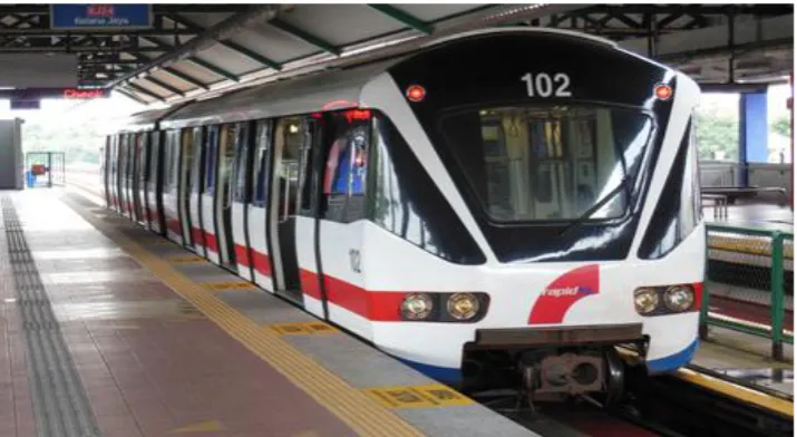
Figure 1.4: LRT Rapid KL at Kelana Jaya Station (Schwandal R., 2007)
[image:19.595.140.498.356.552.2]4
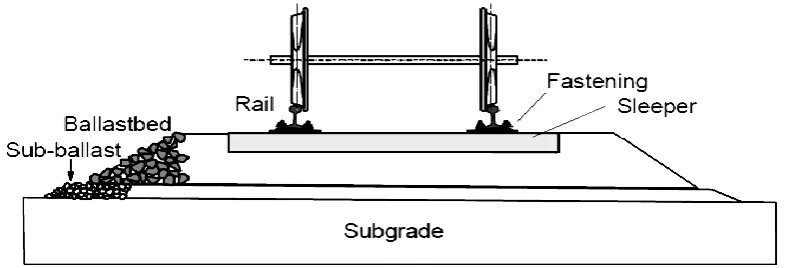
Figure 1.5: Typical infrastructure for ballasted track (Dahlberg, 2004)
[image:20.595.126.506.355.578.2]5
Figure 1.7: Rail track infrastructure (Station in KTM Gemas, 2013)
The term „ballast‟ used in railway engineering refers to the coarse aggregates above the subballast layer and subgrade. Studies carried out by Bhanitiz (2007) and Indraratna et al. (2001) reported on the behaviour of ballast deformation and breakage under static and dynamic loading. Khabbaz and Indraratna (2009) also found ballast to break down under the cyclic load from heavy trains as shown in Figure 1.8.
As summarised by Selig and Waters (1994), vertical and horizontal movements caused by traffic loads are attributed mainly to the deformation and densification of the ballast. Rail track performance depends on the ballast as the main material and leads to poor ride quality, requiring either speed restrictions or maintenance to realign the tracks (Anderson and Key, 2000).
6
Figure 1.8: Tracks fouls due to ballast degradation and contamination (ARTC, 2015)
1.2 Problem statement
In railway engineering, ballast play a crucial part in transmitting and distributing the wheel load to the rail track foundation as well as support the rails and sleepers (Indraratna et al., 2007). Ballast are highly susceptible to subsistence due to both vibration transmitted by the passing trains, as well as the breakage of the ballasts themselves with repeated impact. Based on conventional triaxial tests, Janardhanam and Desai (1983) concluded that the particle size of ballast significantly affect the overall resilient modulus, volumetric and shear behaviour. It follows that track settlement is very much dependent on the ballast quality and its response to traffic load.
Tennakoon et al. (2014) stated that contamination on ballast layer influence
7 gradation, presence of water or ballast moisture, dynamic loading pattern and the frequency.
Ballast is able to allow the track misalignment caused by from the lateral movement from the passing trains on curved track (Lam and Wang, 2001). In addition, weather and water also could cause damage and crushing of ballast by axle weight. The damage on ballast will lead to tracks “pumping” with the train‟s passing, which eventually causes damage to the rail or sleepers (Railway Technical, 2014). Track “pumping” is a continuous loop of ballast and subgrade movement which creates on up -down motion. This affects the comfort of passengers on board as well as imposing additional wear on the rolling stock (Esveld, 2001). Fouling is the proven ballast when it starts to damage, contamination, gradation changes and performance reduction to suffer form. This condition affects the ballast size distribution under the sleepers in certain areas along the rail track, resulting in uneven support of the rail tracks (Siddique and Naik, 2004).
Degradation of ballast also contributes to increase frequency of maintenance and rehabilitation cost too. It would be desirable if measures could be taken to minimize the wear and tear effect of the rail traffic, consequently prolonging the life span of the ballast. This because the wear and tear on the ballast could increase the maintenance cost by realign the rail, replacement of tracks. Khabbaz and Indraratna (2009) highlighted that the main causes of ballast degradation include excessive dynamic loading, vibration, temperature, moisture fluctuation and impact load from severe braking.
8 the tyres do not decompose and it is susceptible to fire hazards (Vinot and Singh, 2013).
1.2 Scope of study
This study is an exploratory work on the ballast-rubber tube composites which involves measurements with the direct shear test. The rubber inclusions are incorporated in the specimen in various configurations. The use of new inner tube as the rubber elements was to ensure the consistency of the specimen tested.
Rail track ballast regularly exposed to the weather and oil contamination. Oil contamination could happen due to the fuel leak and friction from wheel braking. Simulations of the ballast with these conditions were achieved by submerging the ballast with water, acid and lubricant oil for two weeks (14 days). A total of 132 specimens were tested:
i) Control sample (dry, wet, acid and lubricant oil)
ii) Dry aggregates + rubber tube (new and used)
iii) Wet aggregates + rubber tube (new and used)
iv) Hydrochloric acid aggregates + rubber tube (new and used)
v) Lubricant oil aggregates + rubber tube (new and used)
9 1.4 Aim and objectives
The ultimate goal of this study is to verify that rubber inclusion could be more effectively improve the shear resistance in ballast layer with various configurations. The objectives for this research work are:
a) To determine the shear resistance of ballast aggregates with rubber inclusions
in various configurations through direct shear test.
b) To identify the effect of simulated exposure to moisture, acid and oil
contamination on the composite material (ballast-rubber mix).
1.5 Significance of study
The importance of this study is to determine the potential of rubber inclusions in increasing the shear resistance of ballast aggregates in several predetermined configurations. By having the rubber inclusion in the ballast layer, shear resistance could be increased, consequently reducing the wear and tear for better and longer performance.
10 1.6 Thesis outline
Outline of this dissertation is summarized as follows. Chapter 1 presents the problem statement, objectives and scope of the study. Chapter 2 presents the literature review on the project, which included the background and significance of the ballast aggregates as the part of railway track components and the properties of materials. It also includes reviews on the rubber inclusion with granitic aggregates and granular materials by using the standard direct shear box.
Chapter 3 presents details of the measurements and tests for collecting the laboratory test results. Chapter 4 analyses and the results mainly from shear box test. The discussions include assessment from the results obtained. Chapter 5 presents the conclusions and recommendation for future work.
1.7 Summary
CHAPTER 2
LITERATURE REVIEW
2.1 Introduction
This chapter presents a literature review related to ballast and rubber elements. This literature review focuses on the following sections:-
a. Ballast and the rail track environment
b. Particle breakage and the associated with the ballast degradation
c. Ballast contamination
d. Rubber elements and its related functions
e. Shear strength associated with granular materials and rubber mixtures
2.2 Rail track
2.2.1 Track components
12
Figure 2.1: Typical of railway track components (Esveld, 2001)
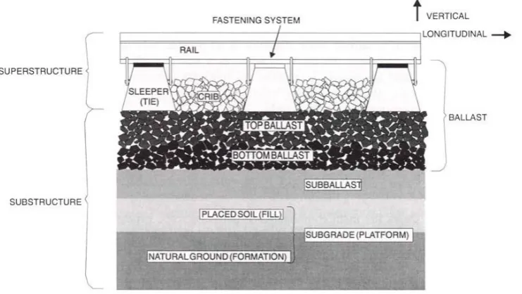
Figure 2.2: Principle of track structure for longitudinal structure(Esveld, 2001)
The rails made from the steel girders that carried the axle load of train (Bindra, 1976). Therefore, the material for rails should be required in qualities of strength, fatigue endurance, wear and the resistance in corrosion (Bonnett, 2005). The functions of rails were to distribute the wheel load from train and transfer it to the sleepers system then to the substructure system. Fastening system for rails was between rails and sleepers in order to resists the forces from vertical, lateral, longitudinal and overturning movements of the rails (Wee, 2004).
[image:28.595.116.511.306.440.2]13 depth (Wan Azlan, 2012). According to Bhanitiz (2007), subgrade was the track foundation which from the existing natural soil and also similar with other foundation behaviour that has excessive settlement should be avoided. Li and Selig (1995) mentioned that the excessive track settlement is generally due to the accumulated plastic deformation of ballasts and substructures layers. However, this gradual accumulation of permanent strains with traffic loads is often overlooked as dynamic records often show negligible elastic deformation of the track support system, where only static measurements reveal the accrued plastic strains (Yoo and Selig, 1979). Furthermore, Dwyer-Joyce et al. (2003) simulated rail-wheel contact with ballast and found that crushed ballast do not only indent and roughen the metal, but inadvertently increase the traction level and reduce the residual fatigue life of the contact.
2.2.2 Track forces
According to Bhanitiz (2007), the railway track has some forces such as vertical, lateral and longitudinal directions act on the track structure due to the movement traffic and the changing temperature. The acceleration and braking from the trains had created the longitudinal forces and gave the thermal expansion or contraction of the rails.
14
Figure 2.3 (a): Layout of track forces (Bhanitiz, 2007)
Figure 2.3(b): Layout of track forces (Bhanitiz, 2007)
2.2.3 Track maintenance
The railway track should have some maintenance in order to provide good performance and comfort to the train passengers. The track ballast in railway system exists for more than 150 years in the railway industry and it has become the basic thing in track design (Edwards, 1990).Therefore, the maintenance usually takes plan in one to three years.
[image:30.595.126.497.73.282.2] [image:30.595.113.488.328.478.2]15 Maintenance techniques had reached the high standard of development with adoption of mechanization in most of the operations (Edwards, 1990).The maintenance for the railway track have two methods such as tamping and stoneblowing, as shown in Figure 2.4. The frequency of maintenance the track based on the frequency of train runs in a year. It depends on the defects on the rail track and the foundation. Due to the new technology, the defects or deformation on the track can be detect by using the track circuit which transfer the information to the control room operators to make the action.
[image:31.595.120.511.441.672.2]According to Khabbaz and Indraratna (2009), there are two types of track such as slab track and ballasted track. For slab track, it can be more effective in the cost when the life-cycle maintenance were considered. Slab track also could provide some advantages such as free of maintenance, less traffic disruption and no dust emission. However, this type of track may not be favourable due to the high cost in construction. As such, ballast track is still widely used due to its effectiveness, efficiency and relatively easy maintenance.
16 2.3 Ballast
2.3.1 Ballast properties
In railway track components, ballast is the most important for the track that placed on top of the track subgrade in order to support the weight of track structure and the dynamic loading from passing trains. Usually ballast providing tensionless elastic support, a free-draining coarse aggregate layer typically composed of crushed stones, gravel and crushed gravel (Wan Azlan, 2012).
According to Pires and Dumont (2013), the depth of ballast structure in rail track is 300-500 mm. Ballast should in angular shape of gravel that has granular fractions between 22 mm and 63 mm. Materials for the ballast mostly include dolomite, rheolite, gneiss, basalt, granite and quartzite which is composed of medium to coarse gravel sized aggregates (Indraratna et al., 2007). Ballast is made up of stones from granites or a similar that should be rough in shape to improve the locking of stones. In Malaysia, granite is commonly used as track ballast, as can be seen at KTM and ERL operations.
17
2.3.2 Functions of ballast
Based on Selig and Waters (1994), Mundrey (2000), Esveld (2001), Dahlberg (2003), Kaewunruen and Remennikov (2008), the fundamental functions for ballast in railway track engineering can be summarised as follows:-
(a) Provides and resists vertical, lateral and longitudinal forces stability to track. (b) Distributes the load from sleepers in order to resist the subgrade from high
stresses so that there will not have permanent settlement occur on track.
(c) Ballast also could absorb the shock from dynamic loading by providing
resilience bed for sleeper.
(d) Facilitate water drainage flow from track structure.
(e) It also gives easy maintenance surfacing and lining operations.
(f) Protects formation against rains and winds.
(g) Protect the sleepers form capillary moisture of structure.
(h) It can slow the vegetation growth and the fouling effect can be resist from surface-deposited materials.
(i) Reduce bearing stresses from the sleepers to acceptable stress levels for underlying layers
(j) Allow optimum global and local settlement
2.3.3 Ballast Specification and Testing
All the specification and types of testing that need to conduct should be referring to the standard. In Malaysia, standards used British Standard (BS), United States (AREMA) or Japanese Standard. The standard usage is based on client demand and suitable for this country. In this case, ballast specification and testing by referring to British Standard and American Standard Testing method (ASTM).
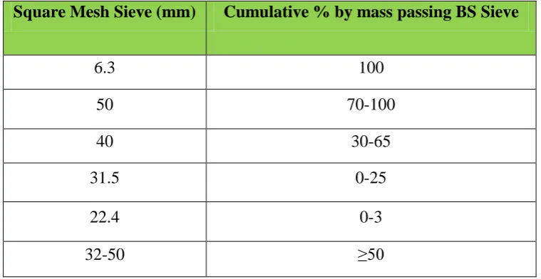
18 ballast track specification which are ballast grading, Los Angeles Abrasion (LAA), micro-Deval attrition (MDA), flakiness index and elongation. The particle size distribution for ballast is shown in Table 2.1.
Table 2.1: The specification for ballast particle size distributions
2.3.4 Ballast degradation and fouling
Ballast could be damaged because of the cementation with the accumulation of fines which occur from the tamping action and other loads. This could reduce the ballast size in certain area under sleepers and along the railway track. It also could result in uneven support of the railway (Lam and Wang, 2011).
According to Khabbaz and Indraratna (2009), the degradation on ballast can occurs because of the excessive dynamic loading and vibration, temperature and moisture fluctuation and also impact load on ballast due to severe braking. Three ways in ballast particles to degradation as following:-
(a) Small-scale asperities by grinding off (abrasion).
(b) Fracture or split of individual particles.
(c) The fragments and angular projection by breaking of that influence the initial
settlement.
Square Mesh Sieve (mm) Cumulative % by mass passing BS Sieve
6.3 100
50 70-100
40 30-65
31.5 0-25
22.4 0-3
19 When ballast start damaged, contaminated, gradation changes and performance reduce then this process called as fouling. The effect for the fouling ballast depends on the types of the material, the degree it fouling and water contents (Wee, 2004).
[image:35.595.128.487.331.460.2]Drainage is one of the main purposes in railway ballasted track by providing the large voids and storage of fouling materials. This could be happen because when the fouling degree increases, large voids will fill in with slowly by the fouling materials and the permeability of ballast become decrease such in Figure 2.5. Therefore, this will create pore water pressure and the fouling materials mix with the water (Wee, 2004).
Figure 2.5: Fouling ballast (Indraratna et al. 2014)
2.4 Particle breakage on aggregates
According to Bhanitiz (2007), particle breakage in an aggregate probably increases when the macroscopic stress been applied, the increasing in particle size and the reduction in number of contacts with other particles. When there has effect on the sizes, the particle become larger and the strength will reduced.
20 break easily. Based on conventional triaxial test, Janardhanam and Desai (1983) concluded that the particle size of ballast significantly affect the overall resilient modulus, volumetric and shear behaviour. It follows that track settlement is very much dependent on the ballast quality and its response to traffic load.
There has an alternative that introduced by Indraratna et al. (2005), about the ballast breakage index (BBI) based on particle size distribution (PSD) curves. BBI is calculating on the basics changes in fraction passing a range of sieve as shows in Figure 2.6. The increasing in degree of breakage could cause the PSD curve to shift further towards the smaller particles size region on the PSD conventional plot. At area A between the initial and final, PSD increases results in a greater BBI value. If BBI has a lower limit of 0, means that there has no breakage happen then the limit must be upper limit of 1. BBI can be calculated with the Equation 2.1 by referring to the linear particle size axis. Figure 2.7shows when the ballast reaction or condition after received some contact forces to the ballast surface.
Where,
A = area
B = the potential breakage or area between the arbitrary boundary of maximum breakage and the final PSD.
A
21
Figure 2.6: Ballast breakage index (BBI) calculation method (Indraratna et al. 2005)
[image:37.595.139.476.475.618.2]22 2.5 Ballast contamination
Contamination on ballast which cause by subgrade pumping and other lubricant for example coal is one of major problem for track deterioration in many countries over the world. Tennakoon et al. (2014) stated that any lubricant may induce load bearing capacity or shear strength on ballast layer reducing and impede the drainage of track. Ballast contamination could effect on the ballast layer and also transfer the pollutants into the soil or underground water.
Ballast gravels were also constantly exposed to the other pollutants such as acid rain because it lay on top of the rail track. Figure 2.8 and 2.9 shows the picture of ballast contamination due to clay pumping and coal contamination. Other than that, the contamination frequently happened due to the leaking from fuel tank, grease dropping and heavy metals which produced from the train. It could occur from the contact between wheel and rail or wheel and brake pad when braking (Cho et al. 2008).
23
Figure 2.8: Ballast contamination due to clay pumping in Ashfield, New South Wales, Australia (Tennakoon et al., 2014)
Figure 2.9: Ballast contamination due to coal contamination in Rockhampton, Queensland, Australia (Tennakoon et al., 2014)
2.5.1 Acid rain effect
[image:39.595.116.515.354.534.2]24 (1990) had mentioned the contamination of toxic gasses into the main cause of acid rain especially in urban and industrial areas.
Acid rain can be any other form precipitation that will create it become acidic. Means that, acid rain consists of hydrogen ions but in a low pH. Based on United States Environmental Protection Agency (2012), acid rain primarily emissions of sulphur dioxide (SO2) and nitrogen oxides (NOx). It occurs when the gasses reacts in the atmosphere with water, oxygen and other chemicals to form various acidic compounds. The strongest compounds in rainwater were hydrochloric acid (HCI), HNO, H2SOl bisulphite and ammonia (NH, HSO,).
2.5.2 Lubricant oil effect
As mentioned before, ballast could be contaminated by grease and lubricant oil due to the wheel braking and fuel leaking from the train as in Figure 2.10. This contamination could affect the ballast to become fouling and damage. Lubrication oil or lube oil is the most commonly widely used because of the possible applications. There have two basic categories of lube oil which are mineral and synthetic. Naturally for mineral oils are refined from petroleum or crude oil. The synthetic oils were manufactured from hydrocarbon or ester oil.
105
REFERENCES
Anderson, W.F. and Key, A.J. (2000), “Model testing of two-layer railway track ballast”, ASCE J. of Geotechnical and Geoenvironmental Engineering, 126(4), 317-323.
American Railway Engineering and Maintenance-of-Way-Association (AREMA) (2010), “Ballast specification,”
Bhanitiz, A. (2007), “A Laboratory Study of Railway Ballast Behaviour Under
Traffic Loading and Tamping Maintenance,” The University of Nottingham:
Thesis of PHD.
Bindra, S.P & Bindra, K. (1976), “Elements of Bridges, Tunnel and Railway Engineering,” Published by Dhanpat Rai & Sons.
Bonnett, C.F. (2005), “Practical Railway Engineering 2nd
Edition,” Published by
Imperial College Press, ISBN 1-86094-515-5
British Standards Institution. (1990), “Methods of tests for soils for civil engineering purposes,” Part 7, BSI, London.
British Standard: BS EN 13450 (2013), “Aggregates for railway ballast”.
British Standard: BS EN 933-1 (2012), “Determination of particle size distributions-Sieving methods”.
106
Cerato, A.B. and Luteneggar, A.J. (2006), “Specimen size and scale effects of direct shear box tests of sands,” ASTM Geotechnical Testing Journal, 29(6), 1-9.
Cho, Y., Park, D.S., Lee, J.Y., Jung, W.S., Kim, H.M. and Lim, J.L. (2008), “Dry Cleaning of Railroad Ballast Gravels by Blasting with Thermossetting Plastic Resin Powder,” Korea Railroad Research Inst. Uiwang Korea.
Dahlberg, T. (2004), “Railway Track Settlement-A Literature Review,” Report for EU Project SUPERTRACK, Linkӧping University of Sweden.
Das, B.M. (2010),”Principles of Geotechnical Engineering, 7th Ed.,”Cengage
Learning, ISBN-13: 9780495411321
Dwyer-Joyce, R.S., Lewis, R., Gao, N. and Grieve, D.G. (2003), “Wear and fatigue of railway track caused by contamination, sanding and surface damage,”
Proc. of 6th International Conf. on Contact Mechanics and Wear of
Rail/Wheel Systems, Gothenberg, Sweden.
Edincliler, A, Baykal, G. And Saygili, A. (2010), “Influence of different processing techniques on Mechanical Properties of used tires in embankment
construction,” Waste management, Vol. (30), pp. 1073-1080.
Edwards, J.T (1990), “Civil Engineering for Underground Rail Transport,”
Butterworth & Co. Published, ISBN 0-408-04343-1.
Eisenmann, J. (1995), “Ballastless track as an alternative to ballasted track,” Rail International, 11, 19-28.
Esveld, C. (2001), “Modern railway track 2nd Ed.,” TuDelft University of
107 Garber and Hoel (2010), “),”Traffic and Highway Engineering. 4th Edition, Cengage
Learning, USA
Huat, B. B., Aziz, A. A., & Chuan, L. W. (2008), “Application of scrap tires as earth reinforcement for repair of tropical residual soil slope,” Electronic Journal
of Geotechnical Engineering, 13, 1-9.
Indraratna, B, Salim W, Ionescu D, Christie D. (2001), “Stress-strain and
degradation behaviour of railway ballast under static and dynamic loading,
based on large-scale triaxial testing,” In: Proceedings, 15th International
Conference of Soil Mechanics and Geotechnical Engineering; 2001; Istanbul: 2093–2096
Indraratna, B., Lackenby, J. And Christie, D.(2005),”Effect of confining pressure on the degradation of ballast under cyclic loading,” Geotechnique, 55(4),
325-328
Indraratna,B., Shahin,M.A., Salim,W. (2007), “Stabilisation of Granular Media and Formation Soil Using Geosynthetics With Special Reference to Railway
Engineering,” Faculty of Engineering, University of Wollongong, Australia.
Indraratna, B.,Thakur , P.K. and Vinod, J.S. (2010),”Experimental and Numerical Study of Railway Ballast Behaviour under Cyclic Loading,” Int J. Geomechanics, 10(4), 136-144
Indraratna,B., Ngo, N.T., Rujikiatkamjorn, C. & Vinod, J.S. (2014), “Behaviour of Fresh and Fouled Railway Ballast Subjected to Direct Shear Testing:
Discrete Element Simulation,” Int. Journal of Geomechanics, Vol. 14, pp
34-44.
108
Kawewunruen, S. and Remennikov, A. (2008), “Dynamic Properties of Railway
Track and its Components: a-state-of-the-art review,” Faculty of
Engineering, University of Wollongong, Australia.
Kim, D. And Ha, S. (2014), “Effects of Particle Size on the Shear Behavior of Coarse Grained Soils Reinforced with Geogrid,” Journal of Materials, ISSN
1996-1944.
Kim, Y.T. and Ahn, J. (2011), “Rubber Effects on Geotechnical Properties of Composite Geomaterials”, Proceedings of Twentyfirst Int. Offshore and
Polar Eng. Conference.
Khabbaz, H. & Indraratna B. (2009), “Development of a Smart Tool for Capturing Novel Advancement in Ballasted Rail Track Substructure,” Conference Paper
Published in 8th International Congress on Civil Engineering.
Lam, H.F. and Wang M.T. (2011), “Railway Ballast Diagnose Through Impact
Hammer,” Procedia Engineering 14:185-194
Li, D. and Selig, E.T. (1995): Evaluation of railway subgrade problems, Transportation Research Record, 1489, 77-125
Lowtan, D.M., (2004), “Rail System in Malaysia,” Final Internal Report, Massachusetts Institute of Technology.
Mundrey, J. (2000),”Railway Track Engineering, 3rd Ed.,”Mc Graw-Hill Education.
Nordberg, G.F., Goyer, R.A. and Clarkson, T.W. (1985), “Impact of effects of acid peripitation on toxidity metals,” Environmental Health Perspectives,
109 Olson, R.E. (1989): Direct shear testing, Advanced Geotechnical Laboratory, Dept.
of Construction Engineering, Chaoyang University of Technology.
Pamukcu, S. and Akbulut, S. (2006): Thermoelastic enhancement of damping of
sand using synthetic ground rubber, ASCE J. of Geotechnical and
Geoenvironmental Engineering, 132(4), 501-510.
Panjamani, A. and Manohar, D.R. (2013), “Shear Strength Characteristics and Static Response of Sand-Tire Crumb Mixtures for Seismix Isolation.” The
University of Hong Kong
Pires, J. and Dumont, A.G. (2013),”Railway Embankment Reinforcement Methods-Methods Review,”.
Powrie, W. (1997), “Soil Mechanics: Concepts and Applications,” E & FN SPON, U.K, ISBN 0419197206.
Rubber Manufacturing’s Association (2006), Washington, DC.
Selig,E.T. and Waters,J.M., (1994), “Track Geotechnology and Substructure Management,” Thomas Telford, London
Siddique, R., & Naik, T. R. (2004), “Properties of concrete containing scrap-tire rubber–an overview,” Waste management, 24(6), 563-569.
Sideris, K.K., Manita, P. And Sideris, K. (2003), “ Estimation of ultimate modulus of elasticity and Poisson ratio of normal concrete”, Cement and Composites,
Vol. 26 pp. 623-631
110 Tennakoon, N., Indraratna, B and Rujikiatkamjorn, C. (2014), “Effect of Ballast Contamination on the Behaviour of Track Substructure,” Uni. Of Wollongong, Australia
Vinot, V. and Singh, B. (2013), “Shredded Tyre-Sand as Fill Material for Embankment Application,” Journal of Environment Research and Development, Vol.7, No.4A
Wan Azlan (2012) Numerical analysis on static load capacity of prestressed concrete sleepers under hypothetical bearing pressure distribution. Masters
thesis, Universiti Teknologi Malaysia, Faculty of Civil Engineering
Wee, L.L. (2004),“Mechanics of Railway Ballast Behaviour,” The University of Nottingham, PHD Thesis.
Xiao, M., Ledezma, M. and Hartman, C. (2013), “ Shear Resistance of Tire-Derived Aggregates using Large-Scale Direct Shear Tests,” ASCE.
Yanagida, T., Matchett, A.J. and Coulthard, J.M. (2002), “Damping and elastic properties of binary powder mixtures,” Powder Technology, 127, 107-115.
Yoo, T. and Selig, E.Y. (1979), “Field observations of ballast and subgrade deformations of track,” Transportation Research Record, 733, 6-12.