International Journal of Emerging Technology and Advanced Engineering
Website: www.ijetae.com (ISSN 2250-2459,ISO 9001:2008 Certified Journal, Volume 2, Issue 12, December 2012)
719
Retinal Image Analysis using Ripplet-I Transform and
Segmentation using Morphological Gradient
M.Jenifer Silvia
1, S.Poovizhi
21Assistant Professor,R.M.K. College of Engineering and Technology 2Assistant Professor,R.M.K. College of Engineering and Technology
[email protected], [email protected]
ABSTRACT— The network of the retinal blood vessels is distinctive for each individual. These Blood vessels when segmented can be used for medical applications. Retinal image enhancement is needed before starting vessel detection. It is greatly required to extract certain features that may help in diagnosis and treatment of some diseases such as diabetes. Applications may also include ocular fundas operation as well in human recognition. Intrinsic characteristics of the retinal images make the vessel detection process difficult. Here we propose an algorithm to detect these vessels effectively. The Ripplet I transform has the efficiency in representing edges and textures and it also can be used to capture the 2D singularities along a family of curves in images. Thus applying this transform to enhance the retinal image edges prepares the image for the segmentation part. The segmentation of the image is done using morphological operators. Reconstruction is done using morphological operators which is been used to extract the connected components of an image. Thus resulting in the segmented blood vessels which is been used in medical applications.
Keywords - Image Enhancement, Ripplet transform, Curvelet Transform, Nonlinear approximation, Image segmentation, Morphological gradient, Morphological Reconstruction.
I.INTRODUCTION
Retinal microvasculature is been used to predict diabetic eye disease. Fundas imaging plays an important role in medical diagnosis of primary levels of diabetes and blood pressure as well as cardiovascular disease [1]. The detection and measurement of blood vessels can be used to quantify the severity of the disease. Retinal blood vessel has been shown to change in diameter, branching angles or tortuosity, as a result of diseases such as hypertension, diabetes mellitus or retinopathy of prematurity [2]. Other indirect applications include automatic generation of retinal maps for the treatment of age-related macular degeneration, extraction of characteristic points of retinal vasculature for temporal or multimodal image registration, retinal image mosaic synthesis, identification of the optic disc position and localization of the fovea. The network of retinal vessel is distinctive enough to each individual and thus can be used for biometric identification.
Important structures of human retina used for many applications are vessels, fovea and optical disk. Detection of these structures manually becomes time consuming and also it depends on the expertise of the user. The retinal images are degraded due to imaging conditions that makes the segmentation of the blood vessels difficult. This is because of the uneven background illumination raises the intensity levels in the regions near the optic disk (OD), but the brightness is reduced gradually and the contrast is diminished when the distance to the OD is increased. These are due to the various acquisition processes. In other words, arteries have higher contrast than veins and also thick vessels display a higher contrast with the background than the thin vessels. Thus enhancement is needed before starting vessel detection. Some of the corrupting sources are related to the acquisition process and kind of imagery and others are intrinsic features that make the segmentation difficult [3]. Therefore we propose a method to enhance the blood vessels of the retina so that the segmentation process is made simpler and faster.
International Journal of Emerging Technology and Advanced Engineering
Website: www.ijetae.com (ISSN 2250-2459,ISO 9001:2008 Certified Journal, Volume 2, Issue 12, December 2012)
720
This uses the concept of marker and the mask thus in the segmented image the connected points to the gradient output image is been got.
II. LITERATURE REVIEW
Due to the variations in the intensities of the image the segmentation process becomes difficult thus the image is been enhanced before this process. In most of the cases of image processing Fourier transform is been used. However, Fourier transform provides an efficient representation for smooth images but it is not suitable for images that contain edges. Edges or boundaries of objects cause discontinuities or singularities in image intensity. Wavelet transform is able to efficiently represent a function with 1D singularities [5]. However, it is unable to resolve two-dimensional (2D) singularities along arbitrarily shaped curves since typical 2D wavelet transform is just a tensor product of two 1D wavelet transforms, which resolve 1D horizontal and vertical singularities, respectively. To overcome the limitation of wavelet, ridgelet transform [6] was introduced. Ridgelet transform can resolve 1D singularities along an arbitrary direction. It also provides information about orientation of linear edges in images and it is based on Radon transform [7], which is capable of extracting lines of arbitrary orientation. But ridgelet transform is not able to resolve 2D singularities, Candes and Donoho proposed the first generation curvelet transform based on multi-scale ridgelet [8].Then they proposed the second generation curvelet transform. Curvelet transform can resolve 2D singularities along smooth curves. Curvelet transform uses a parabolic scaling law to achieve anisotropic directionality. But it was not clear why parabolic scaling was chosen for curvelet to achieve anisotropic directionality. And thus generalized Ripplet transform type I was introduced. The purpose of image segmentation is to decompose an image domain into a number of disjoint regions so that the features within each region have visual similarity, strong statistical correlation and reasonably good homogeneity. Mathematical morphology is a well-known technique in which the shape oriented approach treats the image as a set and the kernel of operation, commonly known as structuring element (SE). Morphological operations, like dilation,erosion, opening, closing, top-hat transformation etc. can used for extracting, modifying, manipulating the features present in the image based on their shapes. The shape and the size of the SE play important role in detecting or extracting features of given shape and size from the image [9].The directional gradient is been used so as to segment the enhanced image.
The process of reconstructing uses a binary morphological reconstruction method called the double threshold operator which consist of two ranges of gray values one being include in the other. The image obtained with a narrow threshold range is the marker image and is been used as the seed for reconstruction using the wide range thresholded image the mask image[10].Using the marker and the mask image the new reconstructed image can be got which holds the connected components of the segmented image.
III.IMAGE ENHANCEMENT
The difficuly in image capture of the ocular fundas is image quality. Due to the imaging conditions the segmentation process becomes difficult and thus the image is to be enhanced before the process of segmentation. Image enhancement involves the development or improvement of an image so that the result is been made more the further process i.e.,segmentation. The process might involve improving the contrast or brightening the image.
A. Ripplet I Transform
To generalize the scaling law of the Curvelet transform a new transform called Ripplet transform was introduced. The Ripplet transform has the following capabilities: Multi-resolution, Good localization, High Directionality, general scaling and support, anisotropy, fast coefficient decay. Ripplet transform can represent images more efficiently than DCT and Discrete wavelet transform (DWT) when the compression ratio is high.
B. Concept of Ripplets
Curvelet transform uses a parabolic scaling law to achieve anisotropic directionality. The anisotropic property of Curvelet transforms guarantees resolving 2D singularities along C2 curves. But, it is not clear why
parabolic scaling was chosen for Curvelet to achieve anisotropic directionality. To address this, Jun Xu, Lei Yang and Dapeng Wu proposed a new transform called Ripplet transformType I (Ripplet-I), which generalizes the scaling law. Ripplet-I transform generalizes Curvelet transform by adding two parameters, i.e., support c and degree d. These new parameters, i.e., support c and degree
International Journal of Emerging Technology and Advanced Engineering
Website: www.ijetae.com (ISSN 2250-2459,ISO 9001:2008 Certified Journal, Volume 2, Issue 12, December 2012)
721 ̂ ⃗⃗ ( ) ⃗⃗ ( ( ⃗ ) (1)
Where ⃗⃗ ( ) is the ripplet element function and R=* + is the rotation matrix. We define the element function of ripplet in frequency domain as
̂ ( ) √ ( ) (
) (2)
where ̂ ( ) are the Fourier transform of ⃗⃗ ( ), W(r)
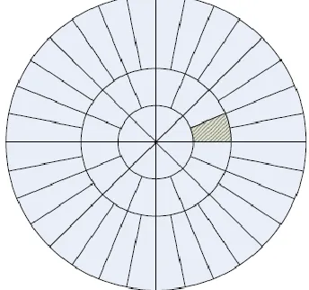
[image:3.612.81.253.307.468.2]is the „radial window‟ on [1/2,2] and V(x) is the „angular window‟ on [-1, 1]. These two windows partition the polar frequency domain into „wedges‟ as shown in Fig. 1.
Fig. 1 The tiling of polar frequency domain. The shadowed ‘wedge’ corresponds to the frequency transform of the element function.
The set of functions*̂ ⃗⃗ } is defined as Ripplet
functions or ripplets for short, because in spatial domain these functions have ripple- like shapes. c determines the support of ripplets and d is defined as the degree of ripplets. Fig. 2shows ripplets with different c and different d in spatial domain. From Fig. 2, we can see that ripplet functions decay very fast outside the effective region, which is an ellipse with the major axis pointing in the direction of the ripplet. The major axis is defined as the effective length and the minor axis, which is orthogonal to the major axis, is the effective width. The values of c and d will actually affect the effective length and width of ripplets in spatial domain. The effective region has the following properties for its length and width: width ≈c x lengthd.
For fixed d, the larger c is, the shorter the width is and the longer the length is. When c is fixed and d gets larger, the width gets shorter and the length is elongated.
The customizable effective region tuned by support c and degree d bespeaks the most distinctive property of ripplets – the general scaling. For c = 1, d = 1, both axis directions are scaled in the same way. So ripplet with d = 1 will not have the anisotropic behavior. For d > 1, the anisotropic property is reserved for ripplet transform. For d = 2, ripplets have parabolic scaling; for d = 3, ripplets have cubic scaling; and so forth. Therefore, the anisotropy provides ripplets the capability of capturing singularities along arbitrary curves. The ripplets as the generalization of curvelet have almost all the properties of curvelet except the parabolic scaling. Ripplets can get multi-resolution analysis of data. For each scale, ripplets have different compact supports such that ripplets can localize the singularities more accurately. Ripplets are also highly directional to capture the orientations of singularities.
(a) (b)
[image:3.612.324.534.326.574.2](c) (d)
Fig. 2 Ripplets in spatial domain with different degrees and supports, which are all located in the center,i.e.,b = 0.(a) a = 3, θ = 3 π /16, c = 1, d = 2, called curvelet particularly.(b) a = 3, θ = 3 π /16, c = 1.5, d = 2.
(c) a = 4, θ = 3 π /16, c = 1, d = 4. (d) a = 4, θ = 3 π /16, c = 1.5, d = 4.
C. Discrete Ripplet Transform (DRT)
International Journal of Emerging Technology and Advanced Engineering
Website: www.ijetae.com (ISSN 2250-2459,ISO 9001:2008 Certified Journal, Volume 2, Issue 12, December 2012)
722
a, ⃗ and are substituted with discrete parameters aj, ⃗ k
and l, which satisfy that a j=2-j; ⃗ k=[c. 2-j. k1, 2-j/d .k2]T and l=
.2-[j(1-1/d)].l, where k=[k
1, k2]T, (.)T denotes the
transpose of a vector and j,k1,k2, l . The degree of ripplets
can take value from R. Since any real number can be approximated by rational numbers, we can represent d with d=n/m, n,m .Usually, we prefer n,m N and n,m are both primes.
The „wedge‟ corresponding to the ripplet function in the frequency domain is
( ) * ⌊ ( )⌋ +,
(3)
The parameter c controls the number of directions in the high-pass bands. d controls how the number of directions changes across bands. For fixed c, d helps to control the resolution in directions at each high-pass band. Given d, c controls the number of directions at all high-pass bands. c and d determine the final number of directions at each band together.
The discrete ripplet transform of an M X N image (n1,n2)
will be in the form of
⃗ ∑ ∑ (
) ̅̅̅̅̅̅̅̅̅̅̅̅̅̅̅̅ ⃗ ( )
( )
where ⃗ are the ripplet coefficients.
The image can be reconstructed through inverse discrete Ripplet Transform
̃( ) ∑ ∑ ∑ ⃗ ⃗ ⃗ ( ), (5)
Ripplets provide a new tight frame with sparse representations for images with discontinuities along Cd
curves.
Nonlinear approximation (NLA) of images is adopted as a common comparison approach to quantify the performance of sparse representation of transforms. Considering we have ortho-normal basis and the corresponding coefficients. Then the coefficients are sorted in descending order with respect to the magnitude. The nonlinear approximation is obtained using n-largest coefficients. Since ripplet transform provides a tight frame, the concentration of ripplet coefficients will lead to more accurate approximation in NLA. The faster the coefficients decay, the more compact energy will be allocated to the fewer large coefficients.
To measure the quality of reconstructed images peak signal-to-noise ratio (PSNR) versus number of retained coefficients is been used.
PSNR=10 ( ), (6)
Where fmax is the maximum value of image intensities and
mse is the mean square error between the reconstructed image and the original image.
IV.IMAGE SEGMENTATION
The enhanced image undergoes the process of segmentation done using morphological operators. The segmentation is the process of partitioning the image into multiple segments. It is to simplify the representation of the image. The enhanced image is been segmented using morphological gradient operators.
A. Morphological operators
The fundamental operators in morphology are dilation, erosion, opening and closing. Choosing the SE is important in morphological image processing because the size, shape and the direction of the SE determines the final result. To detect the complex edges we need advanced SEs. The basis is gathering several SEs in one square window. In other words, decomposing an SE produces the si. Thus, SE is
capable of detecting different edges with different direction, efficiently. For the segmentation process we use morphological gradient. This is the difference between the dilation and erosion of the given image. The areas with the steepest bright to dark or dark-to-bright transitions are been highlighted using these operations.
The edge of image I, which is denoted by Ed(I), is defined
as the difference set of the dilation domain of I and the domain of I. This is also known as dilation residue edge detector:
Ed(I)=(I B)-I (7)
Accordingly, the edge of image I, which is denoted by Ee(I), can also be defined as the difference set of the domain of I and the erosion domain of I . This is also known as erosion residue edge detector:
Ee(I)=I-(I ΘB) (8)
The dilation and erosion often are used to compute the morphological gradient of image I, denoted by E (I):
International Journal of Emerging Technology and Advanced Engineering
Website: www.ijetae.com (ISSN 2250-2459,ISO 9001:2008 Certified Journal, Volume 2, Issue 12, December 2012)
723
The morphological gradient highlights sharp gray-level transition in the input image, and therefore, it is often used as edge detector [12].
B. Image reconstruction
The morphological operator is been used to reconstruct the vessel segments. A correct selection of the marker and mask images allows the generation of binary images. Reconstructing the mask image (I) from marker image (J) is the union of connected components of the mask image which contain at least a pixel of marker image.
( ) ⋃
( )
The ultimate erosion which have to be connected into a single marker can be arbitrarily far away from each other. The correct method in reconstructing the distance function dist(I) from dist(I)-I. The maxima of the resulting function provide a correct marking of the object thus getting a correct segmented image [13].
V.EXPERIMENTAL RESULTS
A. Database
The input image is been got from the DRIVE database which contains 40 color images of retina, with 565 584 pixels and 8 bits per color channel, represented in TIFF format. The images are originally captured using Canon CR5 nonmydriatic 3 charge coupled device (CCD) cameras at 45 field of view (FOV) and were initially saved in JPEG format. The 40 images were divided into a training set and a test set both containing 20 images. The database also contains masks with the delimitation of a FOV of approximately 540 pixels in diameter for each image, and binary images with the results of manual segmentation. In training set a single manual segmentation and in the test set has 2 manual segmentation are available.
B. Implementation
The proposed method is been implemented using MATLAB version 10.The green channel is been selected from the database since the blood vessels in the green channel image have the highest contrast with the background. The blue channel tends to be empty and the red channel tends to be saturated. The green channel image is suitable for images of DRIVE database.
This image is been applied as the input image to which the Discrete Ripplet transform (DRT) is been applied and to that again the Inverse Discrete Ripplet transform is been applied to get the reconstructed image. By varying the values of the parameters c and d the enhanced image is obtained. The process of DRT is done with a non linear approximation (NLA).The final image that is been got is the enhanced image. The PSNR value of the image is been calculated to measure the quality of the enhanced image and for the image 01 of the DRIVE database which was considered as input it was found to be 40.93db. The segmentation is done using the morphological gradient which involves the directional gradient operators taken in four principal directions horizontal, vertical, diagonal (45 ,135 ), and using the difference between the dilation and erosion operators the segmented image is been got. The segmented image undergoes reconstruction so as to extract the connected components of the image. The concept of 8 connected neighborhood is been used. The set of connected components is found and thus resulting in the reconstructed image.
(a)
International Journal of Emerging Technology and Advanced Engineering
Website: www.ijetae.com (ISSN 2250-2459,ISO 9001:2008 Certified Journal, Volume 2, Issue 12, December 2012)
724
(c)
(d)
Fig.3. (a) The input image from the DRIVE database, (b) The image after enhancement, (c) The segmented image, (d) Image after
reconstruction.
VI.CONCLUSION AND FUTURE WORK
The image that is got from the DRIVE database is been enhanced using the Discrete Ripplet transform I, certain characteristics of retinal images make the vessel detection more difficult, thus by performing enhancement before segmentation make the image suitable for the segmentation process. The enhanced image undergoes the process of segmentation done using morphological operators. Morphological reconstruction is done to the segmented image so as to get the connected components of the image thus getting the reconstructed image.
REFERENCES
[1] S. Dua, N. Kandiraju, and H.W. Thompson, “Design and implementation of a unique blood-vessel detection algorithm towards early diagnosis of diabetic retinopathy,” in Proc. IEEE Int. Conf. in Inf. Technol., Coding Comput., pp. 26–31,2005.
[2] M. E. Martinez-Perez, A. D. Hughes, S. A. Thom, A. A. Bharath, and K. H. Parker, “Segmentation of blood vessels from red-free and fluorescein retinal images,” Med. Image Anal., vol. 11, pp. 47– 61,2007.
[3] M.S.Miri and A.Mahloojifar, “Retinal image analysis using curvelet transform and multistructure elements morphology by reconstruction,” in IEEE Trans. On Biomedical Engg,Vol.58,No.5,pp.1183-1192,2011.
[4] J.Xu,L.Yang,D.Wu, “Ripplet: Anew transform for image Processing”.J.Vis Commun Image R.21,pp.627-639,2010.
[5] I. Daubechies, Ten Lectures on Wavelets, SIAM, Philadephia, PA, 1992.
[6] M. Do, M. Vetterli, The finite Ridgelet transform for image representation, IEEE Transactions on Image Processing 12 (1), 16– 28,2003.
[7] S.R. Deans, The Radon Transform and Some of Its Applications, Wiley, New York, 1983.
[8] J.L. Starck, E.J. Candes, D.L. Donoho, The curvelet transform for image denoising, IEEE Transactions on Image Processing 11, 670– 684,2002.
[9] Susanta Mukhopadhyay and Bhabatosh Chanda, “Multiscale Morphological Segmentation of Gray-Scale Images”, IEEE Transactions on Image Processing, Vol. 12, No. 5,pp.533-549, May 2003.
[10] P. Soille, Morphological Image Analysis: Principles and Applications, 2nd ed. Berlin, Germany: Springer-Verlag, 2003, pp. 199–201.
[11] Xu, J. and Wu, D., “Ripplet transform for feature extraction,” in [Proceedings of SPIE Defense Security Symposium 2008], 6970, 69700X–69700X–10,March 2008.
[12] Y. Zhao, W. Gui, and Zh. Chen, “Edge detection based on multi-structure elements morphology,” Proc. 6th World Congr. Intell. Control Autom., pp. 9795–9798, 2006.