International Journal of Emerging Technology and Advanced Engineering
Website: www.ijetae.com (ISSN 2250-2459, ISO 9001:2008 Certified Journal, Volume 2, Issue 12, December 2012)
765
An Efficient 32-Bit Online Error Detection & Correction
Scheme for Embedded Memory
P. K. Dehury
1, T. R. Lenka
21Department of Electronics and Communication Engineering, School of Electrical Sciences,
National Institute of Science and Technology, Palur Hills, Berhampur, Odisha, 761008, India
2National Institute of Technology, Silchar, Assam, India
E-mail: [email protected]
1& [email protected]
2Abstract— As technology scales, VLSI performance has experienced an exponential growth. As feature sizes shrink, however, we will face new challenges such as soft errors (single-event upsets) to maintain the reliability of circuits. Recent studies have tried to address soft errors with error detection and correction techniques such as error correcting codes and redundant execution. However, these techniques come at a cost of additional storage or lower performance. Soft errors are a major reliability concern for today’s nanometre technologies. The errors in register files in Application Specific Integrated Circuits (ASIC) can quickly spread to various parts of the system and result in data corruption which may go unnoticed. For example, Single Error Correction (SEC) Hamming code and Triple Modular Redundancy (TMR) provide a high-level mitigation solution for soft errors. We here studied commonly used algorithm in the industry i.e. hamming code which is used to correct one bit error. However, with recent technology soft error correction needs to be more practicable and efficient and keeping in view of that developed a new algorithm. We have successfully designed, synthesized both the algorithm. After comparing various reports we found that our algorithm is more efficient than hamming code algorithm. Simulation results show that the proposed architecture design based on the our developed new algorithm has low area overhead, 93.5% improvement & It is also observed that the power dissipation is low i.e. 98.9% improvement as compared to the hamming code technique approach.
Keywords—Error correction code (ECC), Error detection and correction (EDAC), single error correction(SEC) single event correction (SEU), soft error, online, single event upset (SEU).
I. INTRODUCTION
In the early days of computers, ―glitches‖ were an accepted way of life. Since then, as computers have become more reliable (and more relied upon), glitches are no longer acceptable – yet they still occur. One of the most intractable sources of glitches has been the transient ―bit-flip‖, or soft memory error: a random event that corrupts the value stored in a memory cell without damaging the cell itself.
International Journal of Emerging Technology and Advanced Engineering
Website: www.ijetae.com (ISSN 2250-2459, ISO 9001:2008 Certified Journal, Volume 2, Issue 12, December 2012)
766 Although the overall area of the register files is small, they are the most frequently accessed part of any memory system. Any error in the register file can quickly spread throughout the system and result in silent data corruption. Although research in the computer engineering community has focused on mitigating soft errors from main memory, regular cache structures -and storage elements in the data path, there is little published data available about SEU protection of register files. Recently a high level architectural study in proposed a solution to mitigate SEU from the register files by using register duplication from the unused registers in combination with Error Correcting Codes (ECC). In this paper we have proposed a new methodology for the design of encoder and decoder for error detection & correction for embedded memory. The proposed scheme used a new methodology for encoding & decoding technique which is better than the hamming code technique.
This paper is organized as follows. In Section II, the literature review is described. Section III, the system architecture is described. The design implementation of proposed architecture based on hamming code & new approach is explained in Section IV. Simulation results & schematic view are described in Section V. Finally, it is concluded in Section VI.
II. LITERATURE REVIEW
Whenever data is stored or transmitted, there is some chance that one or more bits will ―flip‖ that is, will change to an incorrect value. Such incorrect values are called errors; they may be due to a soft error permanent fault (broken hardware) or a transient condition. Transient or soft errors often occur when storing data in DRAM or transmitting a packet across a network connection. As transistors shrink, errors are becoming much more common; in a modern chip the devices are so small that cosmic rays or alpha particles can change the value of bits that are stored in SRAM or registers, or are simply moving across the die.
To counteract this problem and ensure reliable operation, error correcting codes (ECC) are used. Extra bits are stored alongside the data bits to provide redundant information which are related to data or stored bits through some algorithm so that enough bits of carefully chosen redundant information, we can detect or correct the most probable classes of errors. The chosen algorithm should use the optimum number of extra bits as this bits cost some additional circuit to the original hardware.
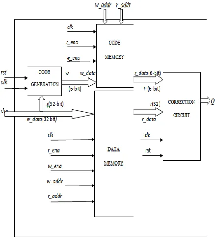
III. SYSTEM ARCHITECTURE 1) Encoder
Encoder is the part of architecture which encodes the message bits with some additional bits i.e. parity bits. It’s input are the message bits from the memory bits which is of 16 bit in our project and produces output which has additional bits requirement which varies based on algorithm requires additional memory to store the same.
2) Decoder
Decoder’s input is encoded message which as stored in the memory detects any error and corrects them with the help of the parity bits. If the data bits are regularly decoded to check any error in the system then there will be less chance of the glitches due to soft error.
3) Memory
It is a structure made of various transistors and victim of soft error which requires some additional bits to store the parity bits in addition to message bits to correct any error occurred.
[image:2.612.334.553.401.653.2].
Fig. 1:Proposed structure of Advance Error Correction cobased Online Error detection and correction scheme for SRAM.
International Journal of Emerging Technology and Advanced Engineering
Website: www.ijetae.com (ISSN 2250-2459, ISO 9001:2008 Certified Journal, Volume 2, Issue 12, December 2012)
767
Signals Description
clk Clock
rst Reset. The negative edge of reset of resets all the output to zero.
din Message Bits. It is a 32 bit message bits which will encoded and decoded at once.
r_ena Read Enable bit. If it is high then read operation is done in memory.
w_ena Write Enable bit. If it is high then write operation is done in memory.
w_addr Address bits. It is a 8 bits which will give the address of memory.
r_addr Address bits. It is a 8 bits which will give the address of memory.
Q Output .It is the output of decoder which produces corrected output if there is any error.
IV. IMPLEMENTATION
Basic idea is to break 32 bit data to ensure more efficiency. As we know more the parity bits, more will be the error detecting capacity. In our design we have used the Cadence NC-Verilog tool. We have written all our codes in verilog language. The NC-Verilog Simulator is the industry’s premier Verilog simulator, delivering high performance and capacity with transaction/signal viewing and integrated coverage analysis. The NC-Verilog Simulator is fully compatible with the Cadence Incisive™ Unified Simulator, providing an easy upgrade path to comprehensive digital verification from system design to system design-in for nanometer-scale ICs [7, 8].
A. Implementation of the proposed architecture Using Hamming code algorithm
Hamming’s development [Ham] is a very direct construction of a code that permits correcting single-bit errors [9]. He assumes that the data to be transmitted consists of a certain number of information bits u, and he adds to these a number of check bits p such that if a block is received that has at most one bit in error, then p identifies the bit that is in error (which may be one of the check bits).
Specifically, in Hamming’s code p is interpreted as an integer which is 0 if no error occurred, and otherwise is the 1-origined index of the bit that is in error. Let k be the number of information bits, and m the number of check bits used. Because the m check bits must check themselves as well as the information bits, the value of p, interpreted as an integer, must range from 0 to m + k , which
m+k+1distinct values. Because m bits can distinguish 2m cases, we must have
2m ≥ m+k+1
k Number of ―information‖ or ―message‖ bits.
m Number of parity-check bits
n Code length, n = m + k.
u Information bit vector, u0, u1, … uk–1.
p Parity check bit vector, p0, p1, …, pm–1.
s Syndrome vector, s0, s1, …, sm–1.
This is known as the Hamming rule. It applies to any bits in a manner described below. Putting the check bits in power-of-two positions (1, 2, 4, 8, 16, 32 …) has the single error correcting binary FEC block code in which all of the transmitted bits must be checked. The check bits will be interspersed among the information advantage that they are independent. That is again can compute each check bit independently of the others.
Putting the check bits in power-of-two positions (1, 2, 4, 8 …) has the advantage that they are independent. That is, the sender can compute p0 independently of p1, p2 … and, more generally, it can compute each check bit independently of the others. As an example, let us develop a single error correcting code for k = 4. 2m possible values
of the m check bits are used, so it is particularly efficient. A code with this property is called a perfect code. This code is called the (7, 4) Hamming code, which signifies that the code length is 7 and the number of information bits is 4. The positions of the check bits pi and the information bits
ui are shown below.
TABLEII
EXAMPLE OF (7,4)HAMMING CODE
p0 p1 u3 p2 u2 u1 u0
International Journal of Emerging Technology and Advanced Engineering
Website: www.ijetae.com (ISSN 2250-2459, ISO 9001:2008 Certified Journal, Volume 2, Issue 12, December 2012)
768 In this work I have done for (38, 32) Hamming code which signifies that the code length is 38 and the number of information bits is 32. The code generation circuit converts the input (32bit) data to output (6bit) data, as given below:-
p[0] is used to detect any change in position R(1,3,5…31)(the Odd position).
p[1] is used to detect any change in position of R(2-3,6-7,….30-31)( positions xxx1x).
p[2] is used to detect any change in position R(4-7,12-15, 20-23,28-31) ( positions xx1xx)..
p[3] is used to detect any change in position R(8-15,24-31) ( positions x1xxx).
p[4] position is used to detect any change in position of R(16-311) ( positions 1xxxx).
p[5] position is used to detect any change in position of R(16-311) ( positions 1xxxx).
B. Implementation of the proposed architecture using our new developed algorithm.
This algorithm is based on the logic that if the message bits are combined in an unique way such that the parity bits formed again forms a unique combination of the parity bits to represent the change in any message bit. At first we tried a combination such that for each message bits there is a unique combination of parity bits by hit and trial and settle for following table. After finding out the table the process is to add the message bits to the corresponding parity bits as shown in Table 3.
V. RESULTS ANALYSIS
The SimVision analysis environment is a unified graphical debug environment for Cadence simulators [7]. The SimVision environment features advanced debug and analysis tools and innovative high-level design and visualization capabilities. The SimControl window, which lets us directly interact with the simulator. We can single step, trace signals, set breakpoints, and observe signals to verify our designs.
A. Verification Process
1) Using Hamming code Technique.
Figure 2 presents the Ncverilog Simvision output of Hamming code technique algorithm with testbench used here is parameterized one. The results shown in the simvision waveform confers the theoretical anticipated results.
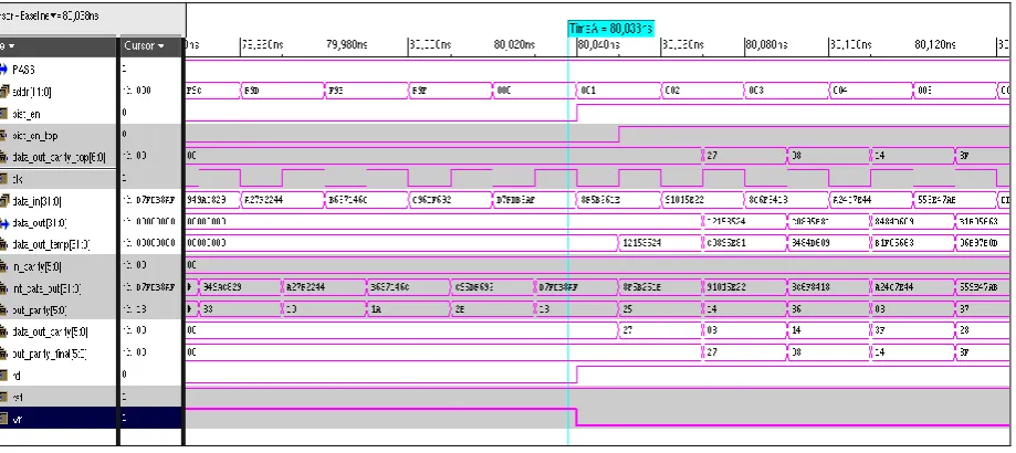
2) Our developed New Algorithm
Figure 3 presents the Ncverilog Simvision output New proposed algorithm with testbench used here is parameterized one. The results shown in the simvision waveform confers the theoretical anticipated results.
TABLEIII FONT SIZES FOR PAPERS
Message bit ( R ) Parity bit ( W )
R(0) p(0)
R(1) p(1)
R(2) p(2)
R(3) p(3)
R(4) p(4)
R(5) p(5)
R(6) p(0)p(1)
R(7) p(0) p(2)
R(8) p(0) p(3)
R(9) p(0) p(4)
R(10) p(0) p(5)
R(11) p(1)p(2)
R(12) p(1)p(3)
R(13) p(1)p(4)
R(14) p(1)p(5)
R(15) p(2)p(3)
R(16) p(2)p(4)
R(17) p(2)p(5)
R(18) p(3)p(4)
R(19) p(3)p(5)
R(20) p(4)p(5)
R(21) p(0)p(1)p(2)
R(22) p(0)p(1)p(3)
R(23) p(0)p(1)p(4)
R(24) p(0)p(1)p(5)
R(25) p(1)p(2)p(3)
R(26) p(1)p(2)p(4)
R(27) p(1)p(2)p(5)
R(28) p(2)p(3)p(4)
R(29) p(2)p(3)p(5)
R(30) p(3)p(4)p(5)
International Journal of Emerging Technology and Advanced Engineering
Website: www.ijetae.com (ISSN 2250-2459, ISO 9001:2008 Certified Journal, Volume 2, Issue 12, December 2012)
[image:5.595.74.534.148.353.2]769
Fig. 2 A Behavioural simulation of proposed structure of Advance Error Correction code based Online Error detection and correction scheme for Eembedded memory using Hamming code algorithm.
B. Synthesis Process
Synthesis in general is a process in which a technological independent code will get converted into the technological dependent code which produces netlist, timing etc files. Cadence Encounter RTL is a top down approach base tool which is used to test a RTL code is synthesizable or not. It tells about the amount of power consumption, approximate area and the speed of the synthesizable form of a RTL code. By combining multi-objective optimization with support for advanced
low-power techniques, Encounter RTL Compiler is the industry’s leading synthesis technology for reducing chip power consumption while meeting frequency goals [7].The libraries used in our synthesis process are:
i. scmetro_cmos10lp_rvt_ss_1p08v_125c.lib.gz ii. pllclk_slow.lib.gz
iii. rom_via_metro_ss_1p08v_1p08v_125c_syn.li b.gz
iv. sram_sp_metro_ss_1p08v_1p08v_125c_syn.li b.gz
[image:5.595.72.541.561.726.2]International Journal of Emerging Technology and Advanced Engineering
Website: www.ijetae.com (ISSN 2250-2459, ISO 9001:2008 Certified Journal, Volume 2, Issue 12, December 2012)
770
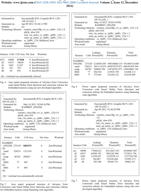
================================================== Generated by: Encounter(R) RTL Compiler RC9.1.203 - v09.10-s242_1
Generated on: Apr 09 2012 01:46:11 PM Module: ecc
Technology libraries: scmetro_cmos10lp_rvt_ss_1p08v_125c 1.0 pllclk_slow 010
rom_via_metro_ss_1p08v_1p08v_125c 1.1 sram_sp_metro_ss_1p08v_1p08v_125c 1.1 Operating conditions: ss_1p08v_125c (balanced_tree)
Wireload mode: segmented Area mode: timing library
==================================================
Instance Cells Cell Area Net Area Wireload --- ECC 18098 117048 0 ZeroWireload (S) d2 14357 94650 0 ZeroWireload (S) d1 3445 21187 0 ZeroWireload (S) d3 252 957 0 ZeroWireload (S) d0 44 254 0 ZeroWireload (S)
(S) = wireload was automatically selected
Fig. 4 Area report proposed structure of Advance Error Correction code based Online Error detection and correction scheme for Embedded memory using our new developed algorithm.
============================================== =
Generated by: Encounter(R) RTL Compiler RC9.1.203 - v09.10-s242_1
Generated on: May 16 2012 02:04:36 PM Module: RAMBIST_ONLINE Technology libraries:
scmetro_cmos10lp_rvt_ss_1p08v_125c1.0 pllclk_slow 010
rom_via_metro_ss_1p08v_1p08v_125c 1.1 sram_sp_metro_ss_1p08v_1p08v_125c 1.1 Operating conditions: ss_1p08v_125c (balanced_tree) Wireload mode: segmented
Area mode: timing library
==============================================
Instance Cells Cell Area Net Area Wireload ---
RAMBIST
_ONLINE 273145 1803475 0 ZeroWireload (S)
ramd 226231 1513143 0 ZeroWireload (S)
ramp 46745 289267 0 ZeroWireload (S)
HM2 77 495 0 ZeroWireload (S)
HM1 77 495 0 ZeroWireload (S)
[image:6.595.71.545.116.761.2](S) = wireload was automatically selected
Fig. 5 Area report proposed structure of Advance Error Correction code based Online Error detection and correction scheme for Embedded memory using Hamming code algorithm.
=============================================== Generated by: Encounter(R) RTL Compiler RC9.1.203 - v09.10-s242_1
Generated on: May 16 2012 02:05:34 PM Module: RAMBIST_ONLINE
Technology libraries: scmetro_cmos10lp_rvt_ss_1p08v_125c 1.0 pllclk_slow 010
rom_via_metro_ss_1p08v_1p08v_125c 1.1 sram_sp_metro_ss_1p08v_1p08v_125c 1.1 Operating conditions: ss_1p08v_125c (balanced_tree) Wireload mode: segmented
Area mode: timing library
==============================================
Leakage Dynamic Total Instance Cells Power(nW) Power(nW) Power(nW) ---
RAMBIST_
ONLINE 273145 1216030.294 950188684.315 951404714.608 ramd 226231 1031115.674 695074279.871 696105395.544 ramp 46745 184093.784 154726707.971 154910801.756 HM2 77 384.543 215923.570 216308.113 HM1 77 372.683 216184.122 216556.805
Fig. 6 Power report proposed structure of Advance Error Correction code based Online Error detection and correction scheme for Embedded memory using Hamming code algorithm.
=============================================== Generated by: Encounter(R) RTL Compiler RC9.1.203 – v09.10-s242_1
Generated on: Apr 09 2012 01:46:29 PM Module: ecc
Technology libraries: scmetro_cmos10lp_rvt_ss_1p08v_125c 1.0
pllclk_slow 010
rom_via_metro_ss_1p08v_1p08v_125c 1.1 sram_sp_metro_ss_1p08v_1p08v_125c 1.1 Operating conditions: ss_1p08v_125c (balanced_tree)
Wireload mode: segmented Area mode: timing library
===============================================
Leakage Dynamic Total Instance Cells Power(nW) Power(nW) Power(nW) ---
ecc 18098 77640.632 10112027.255 10189667.887 d2 14357 64388.782 7061242.948 7125631.730 d1 3445 12194.457 2125550.311 2137744.768 d3 252 764.807 125226.464 125991.271 d0 44 292.586 69169.725 69462.311
International Journal of Emerging Technology and Advanced Engineering
Website: www.ijetae.com (ISSN 2250-2459, ISO 9001:2008 Certified Journal, Volume 2, Issue 12, December 2012)
771 TABLE IV
Summary of comparison of area and power in both the techniques
Specification Hamming code
Our developed new algorithm
Improvement
Cell Area 1803475 117048 93.5%
Power (nw) 951404714.7 10189667.9 98.9%
VI. CONCLUSIONS
In this paper an efficient online error detection and correction scheme for embedded memory is discussed and implemented using Cadence tool. A comparison has been done between new proposed algorithm and Hamming code algorithm. The synthesis report which we obtained from the simulation results have been used the same library constraints and clock frequency (6000ps clock period) and of 180nm CMOS technology. On analysing the synthesis reports on both the algorithms for proposed architecture with same constraints, we found that the proposed new algorithm requires 93.5% less area and 98.9% less power in comparison to the Hamming code algorithm.
ACKNOWLEDGMENT
The authors acknowledge the TIFAC-CORE on
―3G/4G Communication Technologies‖ at National
Institute of Science and Technology for carrying out the research work.
REFERENCES
[1] S. Hellebrand, H. J. Wunderlich,A.Ivaniuk, Y. Klimets, and V. N. Yarmolik, ―Error detecting refreshment for embedded DRAMs,‖ Proc. VLSI TestSymp., 1999, pp. 384–390. [2] H. Lee, J. Sung, and E. Kim, ―Reducing Power in Error
Correcting code Using Genetic Algorithm,‖ Proc. Int. Conf. Computer Information and Systems Science and Engineering,
2007, pp. 179-182.
[3] M. Isaka and M. Fossorier, ―High-Rate Serially Concatenated Coding with Extended Hamming Codes,‖
IEEE CommunicationLetters, Feb. 2005, pp. 160-162. [4] M.Y. Hsiao, ―A Class of Optimal Minimum Odd-Weight
Column SECDED Codes,‖ IBM J. Res. Develop., vol. 14, July 1970, pp. 395-401.
[5] Michael L. Bushnell, Vishwani D. Agrawal, ―Essentials of Electronic Testing for Digital, Memory and Mixed-Signal VLSI Circuits‖, Kluwer Academic Publishers, 2000. [6] J. F. Li, ―Transparent test methodologies for random access
memories with/without ECC,‖ IEEE Trans. on Computer-Aided Design of IntegratedCircuits and Systems, vol. 26, no. 10, pp. 1888–1893, Oct.2007.
[7] Cadence user guide Manuals