© 2016, IRJET | Impact Factor value: 4.45 | ISO 9001:2008 Certified Journal | Page 2292
EXPERIMENTAL STUDY ON LOAD SETTLEMENT BEHAVIORS OF MICRO
PILE UNDER VERTICAL LOADING
Prof
.HARISH C
1, MANJUNATHA .M
21 Assistant, professor, Department of Civil Engineering, EWIT, Bengaluru, Karnataka, India
2 M.Tech Student, Department of Civil Engineering, EWIT,Bengaluru , Karnataka ,India
---***---Abstract - The micro piles are the one which are similar
to piles but their diameter is less than 300 mm .The group micro pile is high performances, drilling and grouting the pile. It is used to resist the horizontal force that is acting additional to the vertical loading to the earth structures. The black cotton soil is swell or shrinking as the water content changes. The pile is transfer of the load below the stratum. The Micro piles have a smaller diameter than conventional pile. This pile composed of a central steel reinforcement circumferential by grout that fastens the pile with the soil.
The experimental model study of single and group pile with different spacing between the piles with four numbers of piles in a group. The piles were installed in black cotton soil and subjected to vertical loading. The Group efficiency of micro pile group having 2.0cm diameter spacing at 1 times the Diameter, 2 times the Diameter and 3 times the Diameter of group micro pile was determined. The group efficiency was commenced to be increasing with spacing from 1D to 2D. The pile group efficiency increases with increase in spacing. The group efficiency decreases as the length of the pile increases.
Key Words: diameter, micro pile L/d ratio 40%, 60%&80%.
1.0INTRODUCTION
The micro piles are the one which are similar to piles but their diameter is less than 300 mm. These micro piles are having the central steel reinforcement. The central reinforcement was covered by mortar. The concreting was carried out by pressure grouting. The
grouting pressure will be in the range of 0.8 Mpa to 1 Mpa. To study the load settlement behavior of the micro piles, model studies were carried out on single micro piles and group of micro piles of different length. The study was also carried out for the group of micro piles placed at different spacing.
1.1 REQUIREMENTS OF PILE FOUNDATION
The pile foundation is required to reduce differential settlement.
The pile foundation of some structures as transmission off –shore platforms are subjected to uplift.
In case black cotton soil is swell or shrinking as the water content changes. The pile is transfer of the load below the stratum.
The collapsible soils as loess a breakdown and sudden decrease in void ratio and increase in the water content.
It is used to resist the horizontal force that is acting additional to the vertical loading to the earth structures.
2. CLAYEY SOIL
© 2016, IRJET | Impact Factor value: 4.45 | ISO 9001:2008 Certified Journal | Page 2293 obtained by open dugout from the draft of 1.5 meter
[image:2.595.68.254.161.461.2]underneath the consistent ground surface.
Table -1: Property clayey soil of soil
PROPERTY VALUES
Specific Gravity 2.72
Water content 28%
Liquid Limit 62.85%
Plastic Limit 21.18%
Plasticity index 41.67%
MDD 15.2 KN/m3
OMC 27.2%
Undrained cohesion 11.348 KN/m2
free swell index 45.47%
The clay soil will obtain air dried and pulverized systemically. The black cotton soil should be passing 4.75 mm Indian standard sieve using for the practice and all the test are determined as per is code 2720 standard . The properties of expansive clay shown in above table.
2.1 EXPERIMENTAL PROCEDURE
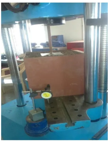
Test was conducted in square test tank. It was built up of mild steel plate obtain size 300×300×300 mm and the thickness 3mm. The test tank size was decided by the footing size. The width of footing was 120×120×6 mm thick. The model footing made up of mild steel plate. The air desiccated to the soil was composite to the optimum water content 27.2%. And the soil was
permeated to the square test tank in three covering and tamping was made to achieve the required density.
[image:2.595.338.528.366.613.2]The micro pile was casted in UPVC pipes. The micro piles were made by mixing the cement & sand at equal proportion of 1:1. By keeping the reinforcement at the centre of UPVC pipe. Micro pile was cured for days. The model test was carried out on these micro piles for different L/d ratio. The test tank was filled with black cotton soil, micro piles were inserted within the soil at spacing. The footing was placed over the inserted micro piles and the load was applied over the footing plate through the loading jack. The same procedure was repeated for L/d ratios.
Fig 1.0 Experimental setup with a square tank and dial gauge
2.2 RESULTS AND DISCUSSION
2.2.1 SINGLE MICRO PILE
© 2016, IRJET | Impact Factor value: 4.45 | ISO 9001:2008 Certified Journal | Page 2294 length and spacing (1D, 2D 3D) conditions. The load
[image:3.595.36.290.189.338.2]settlement behavior was observed for the entire single micro pile test. The settlement was observed upto 25mm.
Fig 1.1 Load -settlement plotting on L/d ratio
2.2.2 ULTIMATE LOAD CAPACITY
[image:3.595.311.565.197.347.2]From the graph it is clear that, for different L/d ratios of single micro pile the load carrying capacity increases in a linear manner
Fig 1.2 Load in KN v/s spacing
2.2.3 MICRO PILE GROUPS
To study the group efficiency of the micro piles, tests were conducted for the different L/d ratios and spacings of micro piles
.
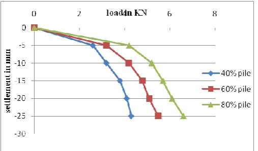
[image:3.595.37.567.382.711.2]Fig 1.3 Load -settlement plotting on L/d ratio with 1D spacing.
Fig 1.4 Load -settlement plotting on L/d ratiowith 2D spacing
.
[image:3.595.312.560.396.522.2]© 2016, IRJET | Impact Factor value: 4.45 | ISO 9001:2008 Certified Journal | Page 2295 2.2.4 ULTIMATE LOAD CAPACITY
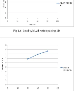
[image:4.595.304.568.56.263.2]The group micro pile on the different Length and spacing for the ultimate load capacity increases with the increase in Length 40%,60%&80% and spacing (1D,2D&3D) the plotting the graph load v/s spacing
Fig 1.6 Load v/s L/d ratio spacing 1D
[image:4.595.35.291.226.393.2]Fig 1.7 Load v/s L/d ratio spacing 2D
Fig 1.8 Load v/s L/d ratio spacing 3D
3.0 GROUP EFFICIENCY
The pile batch efficiency is specifying into the ratio definite group accommodation into the value of the characteristic pile expanse. The group efficiency depends mainly on the spacing between piles, type of soil in which the pile are installed and the manner of pile installation that is driven, bored, cast in –situ etc...
The pile group efficiency, for the piles under vertical loading is calculated from the formula given below.
η = (Qg/nQs) ×100 Where:
η= group pile of the efficiency
Qg = group pile under vertical capacity Qs= single pile under vertical capacity n = pile numbers
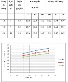
[image:4.595.36.293.302.612.2]© 2016, IRJET | Impact Factor value: 4.45 | ISO 9001:2008 Certified Journal | Page 2296 Table-2 Group micro pile efficiency for different
spacing
Leng th (cm)
L/d rati
o
Single pile (qu)kN
Group pile
(qu) kN
Group efficiency
1D 2D 3D 1D 2D 3D
12 6 4.3 10.8 12.3 13.2 0.62 0.72 0.79
18 9 5.5 11.7 13.5 15.3 0.55 0.64 0.71
24 12 6.6 13.6 15.8 16.7 0.5 0.57 0.63
Fig 1.9 Group efficiency v/s spacing
4.0 CONCLUSIONS
The test was conducted in a square tank. From the load v/s settlement graphs ultimate bearing sufficiency of the group piles were determined from the group efficiency v/s spacing plots the group efficiency of the piles were determined.
The pile group efficiency increases with increase in spacing.
The group efficiency decreases as the length of the pile increases.
To installation of the group micro piles in the weak soil is one of the methods of ground improvement technique.
REFERENCES
[1] Bordolo Sanandam (2014). “A Model Study of
Micro pile Group Efficiency under Axial Loading Condition.” International Journal of Civil Engineering Research ISSN 2278-3652 Volume 5, pp. 323-332
[2] Sonu Mathew.and Swapna Thomas. -(2014).ʺ A
Model Study on Effect of Group Efficiency of Micro pile under Axial” Loading International Journal of Engineering Research & Technology; Vol. 3 Issue 11,
[3] Young-Eun Jang.(2014). ʺDevelopment on the
Micro pile for Applying to Artificial Ground above Railroad Site”. advanced Science and Technology, Vol.55 pp.43-46
[4] Hoyoung Seo, M.ASCE& Monica Prezzi.(2013).ʺ
Instrumented Static Load Test on Rock-Socketed
Micropile.”J. Geotech. Geoenviron. Eng.
2013.139:2037-2047
[5] Morteza Esmaeili (2013). ʺExperimental and
Numerical Study of Micropiles to Reinforce High Railway Embankments.” Int. J. Geomech. 2013.13:729-744.
[6] Núria M. Pinyol& Eduardo E, (2012). ʺDesign of
Micro piles for Tunnel Face Reinforcement: Undrained Upper Bound Solution,” J. Geotech. Geoenviron. Eng. 2012.138:89-99.
[7] Miss.Y.D.Honrao, Prof. A. K. Gupta & Prof. D. B.
Desai. Micro-piles, IOSR Journal of Mechanical and Civil Engineering. ISSN: 2278-1684, PP: 48-50.
[8] Miss.Y.D.Honrao, Prof. A. K. Gupta & Prof. D. B.
[image:5.595.31.301.148.474.2]