© 2016, IRJET | Impact Factor value: 4.45 | ISO 9001:2008 Certified Journal
| Page 2010
Performance and Analysis of Vertical Axis Wind Turbine by Using
Composite Material Blades
B. Naveen Krishna
1, M. Lava Kumar
21
PG Student, Mechanical Engineering, G. Pulla Reddy Engineering College (Autonomous), Kurnool, A.P, India.
2
Assistant Professor, Mechanical Engineering, G. Pulla Reddy Engineering College (Autonomous), Kurnool, A.P,
India.
---***---Abstract –
In today’s life demand of electricity is increasing
all over the world. The production of electricity is less when compared to consumption. By renewable sources we can produce energy which is available in huge amount and can be replaced. Renewable sources are necessary because to reach the demand of energy, increasing cost of fossil fuels used for various purposes and the main thing is environmental pollution. Thus renewable sources are the new techniques that can produce electricity and also it does not cause any environmental effects to human life and surroundings.
Compared to other renewable sources like solar energy, biomass energy, ocean energy, and geothermal energy, wind energy is most important energy source that can easily produce electricity because the source is available all over the world. Now a day’s wind turbine technology is increasing gradually all over the world. By law of momentum theory energy is produced, the produce energy can be stored in the battery can be used for different purposes.
This project describes about the design and fabrication of H shape vertical axis wind turbine by using composite materials as turbine blades that is polyester epoxy fiber. Performance test is carried on vertical axis wind turbine and it is compared with the computer simulation.
Keywords- Vertical axis wind turbine, polyester fiber blades,
aluminum blades, power coefficient, torque coefficient, flow velocities in CFD analysis.
1. INTRODUCTION
Wind is naturally available as a free and clean source of energy on the earth. Wind turbine is a rotary device that extracts energy from wind. Wind is shown as one of the important renewable energy source. The working principle is rotary blades of wind turbine converts wind energy in to mechanical energy. This is just like the airfoil blades of airplane. Blades change according to the direction of wind. The design of blades should be done carefully because to extract power and convert it into torque to drive the electric machine.
Here the blades are manufactured by using composite material. By definition, composite are materials, which comprise of two or all the more synthetically disparate constituents with various properties. Because of their prevalent mechanical properties, higher quality and lower weight, when contrasted with numerous metals and compounds, and in addition the likelihood of fitting the microstructures, composites found a wide applications in auxiliary, common and mechanical building, car industry and also vitality applications.
Why does composite material assume the key part in the wind vitality advancement? The objective of fossil fuel independency in closest decades implies that the renewable vitality segment must be radically expanded.EU set an objective to get 20% of its vitality requirements for renewable by 2020. Keeping in mind the end goal to supply 20% of power for renewable sources to 2020, the EU seaward wind vitality limit ought to be extended by two requests of extent. The high volumes of wind vitality era, important to accomplish this objective, required the establishment and utilization of change extensive wind turbines (8-10MW and higher) remaining in wind homesteads of a few hundred MW. For this situation, the potential expense of repair and substitution of harmed wind turbine may be colossal
In perspective of this necessity, just material with the high quality, weariness resistance and solidness i.e., composites, - can be utilized as a part of wind turbine edges. No different materials, - neither metals, nor combinations, nor wood, - can fulfill this rundown of prerequisites completely.
2. COMPOSITE MATERIAL
© 2016, IRJET | Impact Factor value: 4.45 | ISO 9001:2008 Certified Journal
| Page 2011
polypropylene (PP), There is a noteworthy refinementamongst thermosetting and thermoplastic gums for composites. Thermoset polymers are the network of choice for most assistant composite materials. The single most prominent purpose of enthusiasm of thermo set polymers is that they have a low thickness and can thusly be brought into fibers at low weights. Impregnation of the strands is trailed by substance curing to give a solid structure, which should usually be possible isothermally.
Table 1: Types of Resins Thermosetting
resins Thermoplastic resins Epoxy Polypropylene (PP) Unsaturated
polyester (UP) polyesters (PET, PBT) Thermoplastic Vinyl ester Polyether sulphide (PES)
Polyurethane (PUR) Polyphenylene sulphide (PPS)
Phenolic resin Polyether imide (PEI)
Acrylic resin Polyether ether ketone (PEEK)
Thermoplastic polymers tend to have melt viscosities some place around 500 and 1000 times that of thermosets, which requires higher weights, causes planning challenges and incorporates cost. On the other hand, ideal position of thermoplastics is that the trim should be possible non-isothermally, i.e. a hot melt into a cold mold, in order to fulfill snappy procedure lengths. Thermoplastic composite polymers can in like manner be speedily reused. Dense, more than 90% of polymers used as a piece of composites are thermo sets, with thermoplastic composites still a claim to fame market, principally in view of the difficulties in get ready. The fibers are typically glass, carbon (graphite) or aramid (trade name Kevlar). The fiber stronghold can take any structure: a mat of short cut fibers, a woven fabric, a unidirectional course of action of strands, a turn, a weave
3. MATERIALS USED FOR BLADES
Polyesters are the most extensively used gum systems, particularly in the marine business. By far the bigger piece of dinghies, yachts and workboats worked in composites make usage of this sap system. Polyester saps, for instance, these are of the "unsaturated" sort. Unsaturated polyester gum is a thermo set, prepared for being cured from a liquid or solid state when subject to the right conditions. It is consistent to insinuate unsaturated polyester saps as 'polyester gums', or basically as 'polyesters'. There are two guideline sorts of polyester tar used as standard overlaying systems as a part of the composites business. Orthophthalic polyester gum is the standard money related sap used by various people. Isophthalic polyester sap is in the blink of an
eye transforming into the favored material in business wanders, for instance, marine where its unrivaled water resistance is appealing.
[image:2.595.332.535.147.257.2]
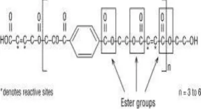
Figure 1: Structure Of Polyester Resin
The figure exhibits the appreciated compound structure of normal polyester. Note the positions of the ester bundles (CO - O - C) and the responsive destinations (C* = C*) inside the nuclear chain. A maker may supply the tar in its key structure or with any of the above included substances viably included. Tars can be characterized to the breaks down requirements arranged only for the development of the force going before frivolity. As has been determined, adequately given time an unsaturated polyester sap will set without any other person's information. This rate of polymerization is excessively direct for down, making it impossible to earth purposes and along these lines impulses and reviving operators are used to fulfill the polymerization of the gum inside a useful day and age. Driving forces are added to the gum structure right away before use to begin the polymerization reaction. The impulse does not participate in the substance reaction yet rather just starts the technique. An animating operator is added to the catalyzed pitch to engage the reaction to proceed at workshop temperature and/or at a more critical rate. Since animating operators have little effect on the tar without a catalyst they are as a less than dependable rule added to the tar by the polyester producer to make a 'pre-enlivened' sap.
3.2. Epoxy:
[image:2.595.55.270.217.390.2]© 2016, IRJET | Impact Factor value: 4.45 | ISO 9001:2008 Certified Journal
| Page 2012
4. MAKING OF BLADES AND DESIGN
DETAILS OF EXPERIMENTAL SETUP
4.1. Design Setup:
Turbine blades are made of polyester epoxy. The epoxy used here is low grade poly vinyl alcohol .The resign material is polyester. For designing blade we have done a carpentry work and then prepared a mould (casting process).
Centre shaft is made of stainless steel.
Ball bearings.
Generator.
4.2. Making of Blades:
4.2.1. Rough Engineering Drawing
:
Firstly we designed an engineering drawing with certain dimensions as per the design parameters of NACA and blades are designed in Q blade software.
TABLE 2: Blade Parameters Blade parameters Dimensions
Chord length 100mm
Circum length 150mm
Height of blade 600 mm
Thickness of blade 3mm
No of blades 2
4.2.2. Pre-form Making
:
Build up a pre-structure in wood or POP on any of alternate metals by cutting the profile in CNC machines. By making this pre-structure design we can undoubtedly make an example which is of reproduction of a completed item this aides in making the work simple and basic yet ought to be done with gifted work. Once in the wake of finishing the pre-structure item we can facilitate continue to Mold making here we can proceed for the further procedure.
4.2.3. Mould making
:
Once a wooden example is made we continue to shape making. In mold making we need to finish the wax on the wooden example where we coat a wax finish for simple evacuation of examples. Next we need to do cotton rubbing for clearing dust stockpiling on the wooden example. Apply PVA (Poly vinyl Alcohol) which is a fluid shape this fills in as a discharging operator. There after we have to apply gel coat
2 times with Resin (cobalt). This further continues by applying glass fabric with tar (cosmetics methyl, ethyl, cornerstone, peroxide) completing with water paper.
4.2.4. Component Casting
:
Rehashing mold making by the required measurements and apply the same procedure like need to finish the wax on the wooden example where we coat a wax finish for simple expulsion of examples. Next we need to do cotton rubbing for clearing dust stockpiling on the wooden example. Apply PVA (Poly vinyl Alcohol) which is a fluid frame this fills in as a discharging specialist. Develop a pre-form in wood or POP on any of the other metals by cutting the profile in CNC machines. By making this pre-form pattern we can easily make a pattern which is of replica of an finished product this helps in making the work easy and simple but should be carried out with skilled labor. Once after completing the pre-form product we can further proceed to Mould making here we can go ahead for the further process.
And the below two figures shown are one is fiber pattern where the polyester and epoxy are laid in it and fiber mould is made in airfoil shape. The airfoil shape is done with wood that is carpentry work. The airfoil shape done by wood is taken and mould work is prepared for it. Then the mould is formed we will coat on with glass fiber and epoxy we will dry it and the shape is formed.
Figure 2 fiber pattern Figure 3 Wood patterns made for fiber Blades
There after we need to apply gel coat 2 times with Resin (cobalt). This further proceeds by applying glass cloth with resin (makeup methyl, ethylene, keystone, peroxide) finishing with water paper. A finished product is ready and pattern is used for multiple design blades.
4.2.5. Final Finished Blade:
© 2016, IRJET | Impact Factor value: 4.45 | ISO 9001:2008 Certified Journal
| Page 2013
Figure 4 Polyester blades4.3. Supply of Wind from Wind Tunnel:
Here we use the wind tunnel for supplying the forced air because the atmospheric wind is less at our surroundings so we preferred wind tunnel and wind tunnel parameters are,
1. The blower consist of an fan of diameter = 400mm 2. The nozzle of the wind tunnel = 300mm
3. The motor is of = 3hp 4. The rpm of motor = 1500rpm
Figure 5 wind Tunnel and Wind Turbine Blades
4.4. Final Experimental Setup:
[image:4.595.55.553.43.837.2]Here we used stainless steel as a centre shaft and used three 6304zz ball bearings for connecting shaft and blades to rotate freely. And a DC motor at the bottom of the shaft connected to series of led lights.
Figure 6 Experimental Setup
5. CALCULATIONS AND ANALYSIS
5.1. Calculations:
The results for vertical axis wind turbine are calculated according to the design parameters of blade. They are:
1. Swept area
Swept area = A = H × D (m2)
Where: H = the height of rotor (m). D = the rotor diameter (m).
2. Tip Speed Ratio
Tip speed ratio (λ) = (ωxD)/2V1.
Angular velocity (ω)= 2∏N/60 (rad/sec) Where: N=Number of rotations (RPM).
3. Power Coefficient Power Coefficient (
Power developed by turbine from the wind Pt = 0.25×ρ×A (V1+V2) × (V12-V22) (watts)
Where: V1 and V2 are velocities from wind
Tunnel (m/sec).
ρ = Density of air is 1.12(kg/m3)
Power developed by wind PW = 0.5×ρ×A×V13 (watts)
4. Torque Coefficient
Torque coefficient (Ct) =Tb/Tw
Where: Tb = Torque developed by blades
Tw = Torque developed by wind
Torque ( ) =
Max Torque ( Where:
According to the formulas of design parameters we have to take the experimental readings and readings are shown in below tabular column with, distance between wind tunnel and experimental arrangement, inlet velocity V1 from
wind tunnel to the blades of wind turbine, outlet velocity V2
[image:4.595.105.252.88.254.2] [image:4.595.59.265.395.524.2]© 2016, IRJET | Impact Factor value: 4.45 | ISO 9001:2008 Certified Journal
| Page 2014
TABLE 3: Experimental ReadingsS.no
Distance
(mm)
Velocity
V1(m/sec)
Velocity
V2(m/sec) RPM
1 500 15.6 10.1 230
2 600 15.3 9.5 200
3 700 15.2 10.5 190
4 800 15 10.8 160
5 900 14.8 11.2 120
6 1000 14.4 10.3 108
7 1200 14.2 9.3 105
8 1300 13.8 9.1 100
The graphs are plotted for tip speed ratio, torque coefficient and power coefficient which we calculated according to the design parameters.
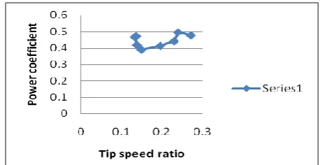
Chart1: Tip speed ratio vs Power coefficient
From the above figure it is clear that power co-efficient first decreases as tip speed ratio increases. Then as tip speed ratio still increases then power co-efficient also increases slightly. But the power co-efficient for the wind turbine will be less than Betz limit that is 59.4.
Chart2: Tip speed ratio vs Torque coefficient
From the above figure it is clear that torque co-efficient decreases as tip speed ratio increases. Further increase in tip speed ratio results increase in torque coefficient.
5.2. CFD Analysis
For the above blade design we have used FLUENT CFD ANALYSIS and at different velocities we have taken the velocity magnitude, pressure coefficient and temperature.
[image:5.595.46.277.408.526.2]The readings are taken at 2m/sec, 10m/sec, 13m/sec and 15m/sec at mountains region and hill valleys. Here Showing results for CFD analysis at 15m/sec because the more variations are occurred here due to high speed of velocity at high peak regions.
Figure 7 Variation of Temperature
The above figure says that the variation of temperature at mountains and hill valley which is taken for 15m/sec.
Figure 8 Variation of Pressure
[image:5.595.314.551.454.579.2]The variation of pressure at blades is shown in the figure and readings are taken at different velocities.
[image:5.595.45.282.625.745.2]© 2016, IRJET | Impact Factor value: 4.45 | ISO 9001:2008 Certified Journal
| Page 2015
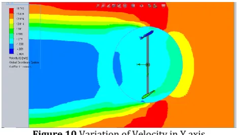
The readings are taken in x and y directions for the [image:6.595.44.280.191.324.2]variation of velocity are shown with original variation of temperature. Both x and y directions are shown because of the rotational moment when chord angle is changed. The velocities vary due to change in different chord angles. The values are not mentioned because at different velocities we have taken the readings vary.
Figure 10 Variation of Velocity in Y axis
Here we can observe the variation of velocities in x and y directions because it varies due to direction of wind and change of chord angle.
Figure 11 Variation of Velocity in X axis
In CFD analysis we have shown the variations in temperature, pressure, velocity at different velocities.
6. CONCLUSIONS
In this project a new design and fabrication of two blades H-rotor vertical axis wind turbine is done. The experimental comparison is done for various wind parameters when the H-rotor wind turbine is tested at the outlet end of wind tunnel
1) For the wind turbine when tested at the end of wind tunnel the power co-efficient is more because due some air losses the outlet wind velocity decreases from the outlet of wind tunnel.
2) The theoretical power developed by the turbine is better when wind turbine is tested at the outlet end of wind tunnel. Because as in the calculations, the outlet velocity of the wind is reduced due to
some air losses then the theoretical power developed by the wind turbine is increased. 3) To calculate torque co-efficient torque meter can be
used. But due to unavailability of the instrument the torque is derived from theoretical calculations. By the calculations it is observed that as inlet velocity and speed of turbine increases then torque developed also increases.
4) In this project the tip speed ratio for two blades H-rotor wind turbine is less than one. Tip speed ratio mainly depends on the speed of the wind turbine. As speed increases then tip speed ratio increases and vice versa.
5) By the experiment conducted the torque co-efficient is more for the wind turbine tested at the end of the wind tunnel.
6) By CFD analysis variations of pressure co-efficient, velocity, turbulent kinetic energy, and turbulent intensity are high for wind turbine blades at the inlet.
7. REFERENCES
1) Giberti, H., Prato, L., Resta, F. ”Design of an actuation system for a variable pitch axial fan” (2011) IMETI 2011 - 4th International Multi-Conference on Engineering and Technological Innovation, Proceedings, 1, pp. 19-24.
2) .Sanghyeon Kim, Cheolung Cheong “Development of low noise drag type vertical wind turbine in science direct web on 24th September 2014.
3) Ashwin Dhote, Prof.Vaibhav Bankar. “Design, analysis and fabrication of savonius vertical axis wind turbine (june 2015)” IRJET published in volume-2, issue-3.
4) M. S. Siddiqui; S. M. Hasan “optimized design of a straight blade urban roof top vertical axis wind turbine”, Energy Systems and Policies (ICESP), 2014 International Conference on Year: 2014, Pages: 1 – 10.
5) S Rolland, W Newton, A.J. Williams, T.N. Croft, D.T. Gethin and M. Cross “Simulation technique for the design of a vertical axis wind turbine device with experimental validation (2013)” in science direct web pages: 1195-1203.
6) Chris Kaminsky, Austin Filush, Paul Kasprzak and Wael Mokhtar “A CFD study of wind turbine aerodynamics”
7) Non conventional source of energy- G.D. Rai. 8) M. Ragheb “Vertical axis wind turbine” University of
Illinoisat urban champaign on web 7th December
20ll.
© 2016, IRJET | Impact Factor value: 4.45 | ISO 9001:2008 Certified Journal
| Page 2016
10) Farooq Ahmad Najar and G.A Harmain “Bladedesign and performance analysis of wind turbine “, IRJCRGG, 2013 volume 5, issue no 2, pages: 1054-1061.
BIOGRAPHIES:
B. Naveen Krishna PG Student,
M. Tech in Thermal Sciences and Energy Systems,
Mechanical Engineering,
G. Pulla Reddy Engineering College
(Autonomous), Kurnool, A.P, India.
Email:[email protected]
Mobile:+919059450042
SRI, M. Lava Kumar Assistant Professor,