© 2016, IRJET | Impact Factor value: 4.45 | ISO 9001:2008 Certified Journal | Page 2382
Agro Advisory Wireless Sensor System With Zigbee
Mr. Samir P. Mendhe , Prof. Sonal Honale
Asst. Teacher, New Sulabha Coaching Classes, Nagpur, Maharashtra, India
Professor, Dept of M.Tech, Abha Gaikwad Patil College, Nagpur, Maharashtra, India
---***---Abstract -
In the last few years, the occurrences of naturaldisasters have been continuing changing our lives, damaging property and life styles in many different ways. In this paper, we present a system that can be used to prevent enormous damage from natural disasters. In this system, a wireless sensor network based on Zigbee / IEEE802.15.4 standard is utilized as a weather station network sending weather information and disasters’ alerts. The weather information is analyzed by using decision tree techniques to announce the disasters’ alerts. This proposed system takes advantage of wireless sensor networks which can send signals over far distances by using a mesh topology, this transfers the data and also consumes low power. Therefore, this system can be installed in locations that are difficult to hardwire or have no access to electricity.
Key Words: Sensor, Zigbee, Temparature, Humidity, Wind.
1.INTRODUCTION
Natural disasters are becoming more severe. One important reason is the results of global warming around the world causing many of the disasters. To carefully protect people in these areas, we need a monitoring and alarm system. In many events such as landslides and water flooding, they can be warned by a raised alarm within in a specified period. The surveillance system’s equipment is a tool used to measure parameters such as sample temperature, air pressure, moisture, vibration etc. These parameters will vary depending on the requirement of the surveillance system.
Monitoring system, the equipment used for detection is the heart of the work. The monitor system devices are installed in different places. Sometimes it is not easy to install equipment in some areas for many reasons such as lack of access to power or unable to connect to signal wiring. In
addition, tools used for
measurements are very expensive. To resolve this problem, a wireless sensor network can be implemented to help in data communications. The advantages of using a wireless network are: using less energy, no need for hardwiring, and high transmission distance. In this research, the advantages of a wireless sensor network are taken to benefit weather
monitoring stations. Many sensor stations measure and send parameters through a wireless network server. Or if the station is outside the server’s radius, it can send data to the nearest wireless weather station forwarding the data to the server. In addition, the wireless sensor network is easy to maintain, devices are cheaper and uses less energy.
2.REVIEW OF LITERTATURE
We visited Nagpur regional meteorological centre on 8th
September 2009. This MET centre is located at Nagpur Airport. This met centre is governed by Govt. of INDIA Ministry Of Earth Sciences. This centre takes care of weather readings for Nagpur district.
We reported to Mr. P.L. Dewangan (Asst. meteorologist) who welcomed us and helped us for further processes. We wanted to take the readings for following parameters.
1. Wind speed 2. Relative humidity 3. Temperature.
He told us about for the formalities to be carried out and to pay the fees for the requirement. In the mean while we were told to study how these parameters were recorded.
Then we went to recording department, where Mr. Gaikwad (scientific asst.) taught us different techniques to measure the parameters. He informed us about the balloon technique which is used to measure the weather parameters at height above the ground level. This balloon is tied to radiosonde device which is radiog transmitter and measuring equipments. This device transmits the readings at different levels around 16 km from the surface. Temperature, humidity, light parameter and record weather statistics for planning, and presented the development of a wireless sensor for use in various applications.
3. RELATED WORKS
3.1. Decision Tree
© 2016, IRJET | Impact Factor value: 4.45 | ISO 9001:2008 Certified Journal | Page 2383
of action. The primary advantage of a decision tree is that itassigns exact values to the outcomes of different actions, thus minimizing the ambiguity of complicated decisions. Because they map out an applied, real-world logical process, decision trees are particularly important to build "smart" computer applications like expert systems. They are also used to help illustrate and assign monetary values to alternative courses of action that management may take.
In this research, the use of a decision tree will process input parameter to alarm when an inputted parameter matches predefined conditions.
3.2. Zigbee Standard
ZigBee/IEEE 802.15.4 is the only standards-based wireless technology designed to address the unique needs of low-cost, low-power wireless sensor and control networks in just about any market. Since ZigBee can be used almost anywhere, is easy to implement and needs little power to operate, the opportunity for growth into new markets, as well as innovation in existing markets, is limitless.
3.3. XBee
XBee [7] is a device used to send and receive data wirelessly and can build up a ZigBee/IEEE 802.15.4 network reference standard . XBee functions can be divided by network topology in different ways including the Coordinator, Router and End Device.
• Topology
To create a wireless network of ZigBee, it will consist of at least two nodes including coordinator node and sensor node types (Router/End device) to be able to communicate and work in PAN (Personal. area network). Wireless sensor network topology an be divided into 3 topologies: Star Topology , Cluster Tree Topology and MESH Topology. 1.Star Topology
2.Cluster Tree Topology 3.MESH Topology
Star topology or a Broadcast is non-specific transmission. All destinations or on the same network can Get all the information any time.
The transmission of data transmission, such as E0 need
contact to C0, but C0 is far from E0 and E0 can connect to R0,
and R0 is between E0 and C0, so Cluster Tree will use R0 as
an intermediary (Repeater) connecting the 2 nodes C0 and E0.
Mesh topology is the most effective since data can be sent to the target in more ways; it can transfer data to a destination even if parts of the system are lost (depending on system design).
Mesh networks are regularly distributed networks that generally allow transmission only to a node’s nearest neighbours. The nodes in these networks are generally identical, so that mesh nets are also referred to as peer-to-peer (see below) nets. Mesh nets can be good models
for large-scale networks of wireless sensors that are distributed over a geographic region, e.g. personnel or vehicle security surveillance systems.
• Serial Interface Protocols
Xbee module supports both transparent and API(Application Programming Interface) serial interfaces.
- Transparent Operation: when operating in transparent mode, the modules act as a serial line replacement. All UART data received through the DIN pin is queued up forRF transmission. When RF data is received, the data is sent out through the DOUT pin.
- API Operation: API operation is an alternative to transparent operation. The frame-based API extends the level to which a host application can interact with the networking capabilities of the module. When in API mode, all data entering and leaving the module is contained in frames that define operations or events within the module.
4.SYSTEM DESIGN AND IMPLEMENTATIONS
Our wireless sensor network for weather and disaster alert system uses mesh network topology. The system design is divided into two main sections consisting sensor node (Router/End Device Node) and coordinator node.
Fig. 1: System overview consists of Router/End Device Node and Coordinator Node
© 2016, IRJET | Impact Factor value: 4.45 | ISO 9001:2008 Certified Journal | Page 2384
4.1. Sensor Node
The sensor node consists of the microcontroller, temperature and humidity sensor, light sensor, pressure sensor and XBee module. The wireless sensor nodes are programmed with C language . It stays on standby for requests of data transmitted from the server (coordinator with server). Upon receiving the request for weather data, the microcontroller will read the data from different sensors and send the data back to the server.
This experiment is set up with XBee module working in mesh topology. For data transmission, it has only one sensor node which is the coordinator with server for data recording and processing. For the transmission to coordinator, sensor nodes cannot directly contact the coordinator, it needs to transmit data to sensor nodes near the coordinator.
In the API Frame type, it can check whether the data has been sent to the server or not. When the sensor sends data out, the server will receive it and send API Frame back to show completed state. Otherwise, it will retransmit such as the destination offline.
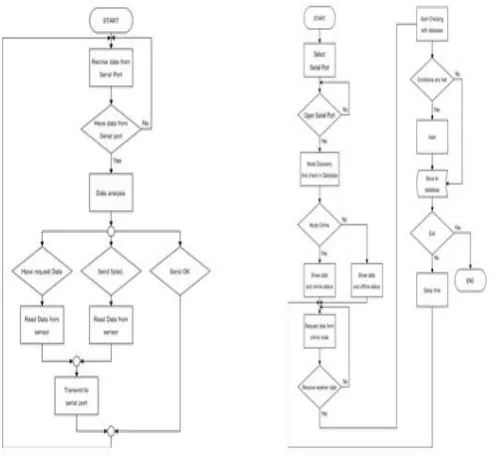
[image:3.595.31.280.357.585.2]
Fig. 3: Flow chart of Sensor node and Server node processes
4.2. Server and Coordinator
On the server side, it has a web/database and connects with XBee (Fig. 3 shows server and coordinator node). The server has an application and web application to control and to manage the system. The server will connect XBee via USB port. When opening the application and selecting serial port to connect to the XBee sensor nodes, the system
will search sensor nodes in the network and display the status and data of the sensor node.
Requested data from the sensor node, the server will be sent API Frame via sensor nodes. When the data is sent out, the status of delivery will change if the sensor node successfully receives the data. But if there is no response from the sensor nodes, the system will again send the request data in a specified period.
When the server receives weather data from sensor nodes, the server will check the weather data with notification value by using decision Tree techniques. If it matches with the pre-conditions, it will notify the system administrator and record of the notification and automatically store weather data to the database
© 2016, IRJET | Impact Factor value: 4.45 | ISO 9001:2008 Certified Journal | Page 2385
Transmitter CircuitZigBee is a standard defines a set of communication protocols for low-data-rate short-range wireless networking. ZigBee-based wireless devices operate 2.4 GHz frequency bands. The maximum data rate is 250 K bits per second. ZigBee is mainly for battery-powered applications where low data rate, low cost, and long battery life are main requirements.
1)To transmit a single variable to a receiver unit which outputs a 4-20mA or 0-10V signal corresponding to the input.
2) To transmit multiple input values to a receiver unit which provides either multiple 4-20mA or 0-10V outputs or a single Ethernet or RS232 connection. The transmitter and receiver units are identical units factory configured for either function.
Receivers
© 2016, IRJET | Impact Factor value: 4.45 | ISO 9001:2008 Certified Journal | Page 2386
TEMPRATURE WORKINGThe key component is the Dallas Semiconductor's DS1621 temperature sensor. This tiny 8 pin IC needs only +5 volts to measure the temperature and to send it out via its IIC bus output. Since many IIC bus devices can be connected in parallel, three address inputs (A0, A1, A2) are provided to select one out 8 addresses the device will respond on. This way, up to 8 sensors can be connected in parallel. I have set the internal temperature sensor to address 0 and the external one to address 1. If you plan to use only one sensor connect it as address 0.
Interfacing the IIC bus to the RS232 com port is a matter of adapting levels. IIC works on 0..5V signals, RS232 uses -12V .. +12V. The trick here is that, altough specified for -12V..+12V, almost all PC com port I know work equally well with 0..5V signals. This eliminates the need to raise the IIC output to RS232 levels, and the SDA data line connects directly to the PC CTS line. On the opposite way, the RS232 signals can damage the IIC inputs, so I placed voltage limiters (R1, DZ2, R2, DZ1) on the SCL clock input and SDA data input. (note that SDA is bidirectional: receives from the DTR line and transmits to the CTS line). Since the circuit draws very little current, there is no need to add an external power supply. The +12V from the RS232 lines are conveyed to the regulator by diodes D1, D2, filtered by C1 and regulated to +5V by the LM2936-Z5. Don't replace it with an ordinary 78L05 regulator unless you want to add an external 9V battery: the LM2936 is capable to regulate even with input voltages near to 6V, as is the case of many serial ports.
HUMIDITY WORKING
The Project circuit comprises sensor parts built using op-amp IC LM324. Op-op-amp’s are configured here as a comparator. Two stiff copper wires are inserted in the soil to sense the whether the is wet or dry. The Computer was used to control the whole system it monitors the sensors and when more than two sensors sense the dry condition then the computer will switch on the motor and it will switch off the motor when all the sensors are in wet. The computer does the above job it receives the signals from the sensors, and this signals operated under the control of software which is stored in ROM.
CIRCUIT DIAGRAM
Power supply
Rectifier Circuit : Rectifier is a circuit which converts the AC electrical energy into Dc electrical energy. For operating of semiconductor devices used in this project we need regulated DC supply. In this project we use centre tap full wave rectifier. Full wave rectifier circuit is capable of converting sinusoidal input into a unidirectional output. The circuit diagram is as shown in the figure.
Filter Circuit : It is seen that the output of the rectifier is not pure DC, because it contain some amount of AC component which is called as ripple factor which gives the fluctuation and hence to minimize the ripple in the output the filter circuit is used. This circuit is connected after the rectifier circuit. In our project capacitor input filter is used. The circuit is as shown in the figure. The capacitor is connected in parallel to minimizethe ripple factor.
Regulator Circuit : In our project for the operation of IC we need +5 volt regulated supply is necessary therefore a voltage regulator circuit is used. A voltage regulator is a circuit that supplies constant voltages regardless of change in the load current. IC voltage regulators are versatile and generally used. The 78xx series consist of three terminal positive voltage regulators. These ICs are designed as fixed voltage regulator and adequate heat sink. It can be deliver output current in access of 1A. These devices do not required external component.
© 2016, IRJET | Impact Factor value: 4.45 | ISO 9001:2008 Certified Journal | Page 2387
PC Interfacing Circuit Receiver sectionPC Interfacing Circuit
In the receiver section the ZIGBEE module can be used as receiver. This module receives the data send by the transmitters. The supply to the ZIGBEE module (3.3V) is given by the supply circuitry in fig with LM317.
To interface with the computer we have to convert the TTL logic into RS232 logic, for this purpose we use the IC MAX232. MAX232 is a dual driver/receiver that includes a capacitive voltage generator. The drivers (T1 & T2), also
called transmitters, convert the TTL/CMOS logic input level into RS232 level. The transmitter (pin 10-T2 in) take input from ZIGBEE’s data out pin (pin 2 of ZIGBEE) and send the output to RS232’s receiver at pin 7 (T2 out) of MAX232. We use four capacitors, two for doubling the voltage and other two for inverting the voltage. The capacitors are connected between pin 1 and pin 3, pin 4 and pin5, pin 2 and VCC, and pin 6 and GND. The transmitter output (T2 out) from MAX232 (RS232 logic) is connected to pin 2 (receive data) of RS232 port. Thus the data received are given to PC. The pin 5 of RS232 port is connected to ground.
Zigbee XBee®/XBee-PRO® ZB RF Modules
The XBee Module 2mW PCB Antenna - Series 2 (ZigBee Mesh) allows a very reliable and simple communication between microcontrollers, computers, systems, really anything with a serial port. Point to point and multi-point networks are supported. These are essentially the same hardware as the older Series 2.5, but have updated firmware. They will work with Series 2.5 modules if you update the firmware through X-CTU. The modules require minimal power and provide reliable delivery of data between remote devices.
ZigBee is a specification for a suite of high level communication protocols used to create personal area networks built from small, low-power digital radios. ZigBee is based on an IEEE 802.15 standard. Though low-powered, ZigBee devices often transmit data over longer distances by passing data through intermediate devices to reach more distant ones, creating a mesh network; i.e., a network with no centralized control or high-power transmitter/receiver able to reach all of the networked devices. The decentralized nature of such wireless adhoc networks make them suitable for applications where a central node can't be relied upon.
ZigBee is used in applications that require a low data rate, long battery life, and secure networking. ZigBee has a defined rate of 250 kbit/s, best suited for periodic or intermittent data or a single signal transmission from a sensor or input device. Applications include wireless light switches, electrical meters with in-home-displays, traffic management systems, and other consumer and industrial equipment that requires short-range wireless transfer of data at relatively low rates. The technology defined by the ZigBee specification is intended to be simpler and less expensive than other WPANs, such as Bluetooth or Wi-Fi.
Features
•250kbps Max data rate • 2mW output (+3dBm) • 400ft (120m) range • Fully FCC certified • 6 10-bit ADC input pins • 128-bit encryption
• Local or over-air configuration
TESTING
© 2016, IRJET | Impact Factor value: 4.45 | ISO 9001:2008 Certified Journal | Page 2388
The least carelessness may lead to the major fault in case ofelectronics circuit and it is depend upon the layout and design of the PCB. Printed circuit board are used to route electrical current and signal through the copper tracks which are primarily bounded to an insulating core.
For the testing of any electronics circuit some common steps are performed. These steps are as follows.
To check the main power source.
To tress out the circuit. In which following steps are followed.
1) The tracks are not open.
2)The distances between two tracks are sufficient to avoid capacitance.
3)The track linked with the other related tracks is proper or not.
4)The jumper which goes from one track to another track should not short with the tracks which are in between required two.
Thus by testing the tracks of the printed circuit board it helps the project for making successful. After testing copper tracks the component were tested with the help of instrument like multimeter, CRO, signal generator etc. After mounting the component on the PCB the possibility of the dry soldering was checked to avoid the possibility of shorting those tracks as well as the tracks were checked individually to avoid the possibility of opening those tracks. This testing was carried out with the help of multimeter keeping in range of Ohm. After all check the power was supplied and the
operation of the circuit it was observed.
Check the supply voltage and voltages at the points where it is known or expected to be of certain value. Check the output voltage and waveform of the circuit by
the equipment such as CRO, signal generator.
Thus by checking the above aspects, it helps the project to become successful.
Testing of Power supply circuit:-
The entire components are tested with the help of multimeter. After testing of component we fix the component on the wet board. Now we give the supply to the transformer and input waveform is to be checked. This procedure is simultaneously carried out for Rectifier, Filter and Regulator circuit. We check the waveform but it is not according to our assumption, because the waveform is started and then it goes to decreasing. Due to this the output voltage is also decreases.
Technology Overview
© 2016, IRJET | Impact Factor value: 4.45 | ISO 9001:2008 Certified Journal | Page 2389
Most ZigBee products are battery powered only with batterylife measured in months, even years. provides an overview of how the technologies differ.
Chart
Zigbee transmitter
Zigbee receiver
Application
In this section, Visual studio C# is selected to develop an application used to control and display the information: Main page, Statistics: Display node information, weather and operation information Alert setting: Configuration and add conditions of the notification.
Results
© 2016, IRJET | Impact Factor value: 4.45 | ISO 9001:2008 Certified Journal | Page 2390
Codingusing System;
using System.Drawing; using System.Windows.Forms; using System.IO;
using System.IO.Ports;
using System.Drawing.Imaging;
namespace TransformerMonitoringAndProtection {
public partial class frmMainTransformer : Form
{
int count = 0;
SerialPort SerialPort1 = new SerialPort(); string DispString;
int windCountOne = 0; int windCountZero = 0; int windFlag = 0;
TimeSpan currentTime, startTime; int windCount = 0;
public frmMainTransformer() {
InitializeComponent(); }
private void btnExit_Click(object sender, EventArgs e) {
if (SerialPort1.IsOpen) {
SerialPort1.Close(); }
Application.Exit(); }
private void frmMainCoalMines_Load(object sender,
EventArgs e) {
btnOpenPort.Enabled = btnClosePort.Enabled = true;
//set images for temperature, gas, humidity picturebox in obtained values
pbTemp.Image = imageList1.Images[9]; pbOil.Image = imageList1.Images[7]; pbOverload.Image = imageList1.Images[8];
lblWarning.Visible = false;
StatusLableWarning.Visible = false;
}
private void serialPort1_DataReceived(object sender, System.IO.Ports.SerialDataReceivedEventArgs e)
{
DispString = SerialPort1.ReadLine();
System.Diagnostics.Debug.WriteLine(DispString); this.Invoke(new EventHandler(DisplayText));
}
private void DisplayText(object sender, EventArgs e) {
txtTerminal.Text = "";
txtTerminal.AppendText(DispString); lblSerialPortValue.Text = txtTerminal.Text; getTGHValues(lblSerialPortValue.Text); string value = lblSerialPortValue.Text;
count += 1;
value = Convert.ToString(count);
textBox1.Text += value.ToString()+
Environment.NewLine;
if (count == 1) {
timer1.Enabled = true; }
else if (count == 15) {
timer2.Enabled = true; }
else if (count == 30) {
timer3.Enabled = true; }
else if (count == 45) {
timer1.Enabled = true; }
else if (count == 60) {
timer2.Enabled = true; }
else if (count == 75) {
timer3.Enabled = true; }
else if (count == 90) {
timer1.Enabled = true; }
else if (count == 105) {
timer2.Enabled = true; }
else if (count == 120) {
timer3.Enabled = true; }
© 2016, IRJET | Impact Factor value: 4.45 | ISO 9001:2008 Certified Journal | Page 2391
string temperatureValue;string OilValue; string OverloadValue;
private void getTGHValues(string strValues) {
string gotValue = lblSerialPortValue.Text;
//get index values of letters
int indexOfP = gotValue.IndexOf("P"); int indexOfG = gotValue.IndexOf("G"); int indexOfS = gotValue.IndexOf("S"); int indexOfH = gotValue.IndexOf("H"); int indexOfM = gotValue.LastIndexOf("M");
//filter out temperature, gas and humidity values from obtained values
temperatureValue = gotValue.Substring((indexOfP + 1), (indexOfG - indexOfP - 1));
OilValue = gotValue.Substring((indexOfS + 1), (indexOfH - indexOfS - 1));
OverloadValue = gotValue.Substring(indexOfM + 1, 2);
//display obtained temperature, gas and humidity values in labels
lblTemperature.Text = (temperatureValue.ToString() + "° C");
lblOil.Text = (OilValue.ToString() + " KM/HR"); lblOverload.Text = (OverloadValue.ToString());
checkIncreasedValues(double.Parse(temperatureValue), double.Parse(OilValue), double.Parse(OverloadValue)); }
private void checkIncreasedValues(double gotTemperature, double gotGas, double gotHumidity) {
if (double.Parse(OilValue) == 93) {
windCountOne = windCountOne + 1; if (windCountOne >= 3)
{
windCountZero = 0; windFlag = 0; }
} else {
windCountOne = 0;
windCountZero = windCountZero + 1; windFlag = 1;
}
label5.Text = windCountZero.ToString(); //MessageBox.Show("asdfasdf");
//check if temperature has increased above 40 degrees
if (double.Parse(temperatureValue) > 80) {
SetImageInPictureBox(); lblWarning.Visible = true;
//StatusLableWarning.Text = "Temperature "; textBox2.Text = " the temperature is high for the crop please provide the proper cooling system";
}
//check if oil has decreased below 70 percent
if (double.Parse(OilValue) < 70) {
SetImageInPictureBox(); // lblWarning.Visible = true; //StatusLableWarning.Text = "";
textBox2.Text = " please provide water for plant"; }
//check if overload has increased above 70
if (double.Parse(OverloadValue) == 93 || double.Parse(OverloadValue) == 0)
{
else {
pboxWarning.Image = null; lblWarning.Visible = false;
StatusLableWarning.Text = StatusLableWarning.Text = "";
int a = +1;
//label5.Text = (a + " KM/HR"); }
}
private void timerOverload_Tick(object sender,
EventArgs e) { if
(System.TimeSpan.Parse(DateTime.Now.TimeOfDay.ToStrin g()) > startTime)
{
timerOverload.Enabled = false; SerialPort1.Write("bbbb"); pboxWarning.Image = null; lblWarning.Visible = false;
getTGHValues(lblSerialPortValue.Text);
StatusLableWarning.Text = StatusLableWarning.Text = "";
SerialPort1.DataReceived += new
SerialDataReceivedEventHandler(serialPort1_DataReceived)
© 2016, IRJET | Impact Factor value: 4.45 | ISO 9001:2008 Certified Journal | Page 2392
//call this method if values increase above normal values and display warning
private void SetImageInPictureBox() {
//Image gifImage =
Image.FromFile(Directory.GetCurrentDirectory()
private void btnOpenPort_Click(object sender,
EventArgs e) {
timer1.Enabled = true;
//Provide the name of port to which device is connected
SerialPort1.PortName = "COM1";
//default values of hardware SerialPort1.BaudRate = 9600; SerialPort1.Parity = Parity.None; SerialPort1.StopBits = StopBits.One; SerialPort1.Handshake = Handshake.None;
SerialPort1.Open(); //opens the port SerialPort1.ReadTimeout = 200;
btnOpenPort.Enabled = false; btnClosePort.Enabled = true;
timerProgressBar.Enabled = true; statusProgressBar1.Visible = true; statusProgressBar1.Value = 0;
statusLabel1.Text = "Initializing Port ... Please Wait !"; }
private void btnClosePort_Click(object sender,
EventArgs e) {
if (SerialPort1.IsOpen) {
SerialPort1.Close(); pboxWarning.Image = null; lblWarning.Visible = false; btnClosePort.Enabled = false; btnOpenPort.Enabled = true;
statusLabel1.Text = "Click Start Button to Initialize Port";
} }
private void timerProgressBar_Tick(object sender,
EventArgs e) {
if (statusProgressBar1.Value != 100) {
statusProgressBar1.Value += 10; }
else {
timerProgressBar.Enabled = false; statusProgressBar1.Visible = false;
statusLabel1.Text = "Checking System ...";
//Get Value from Serial Port through event handler SerialPort1.DataReceived += new
} }
CONCLUSIONS
This research focuses on developing devices and tools to manage, display and alert the weather/disaster warnings using the advantages of a wireless sensor network system in mesh topology. The system can work over far distances. The system uses arduino microcontroller and Xbee Wireless module base on the Zigbee/IEEE 802.15.4 standard. The developed system is very flexible and accurate. The developed system has core competency including 1) display weather information, 2) alert when weather conditions match using decision tree technique and 3) keep weather information statistics.
FUTURE SCOPE
In the field testing, the specification of the device’s communication range is 1 mile at the line of sight. When used in a real environment, the high-rise buildings, it ranges from 300 to 500 meters, the system can work normally. The system can alert when the weather information matches with specified conditions. is the expected output with real output. In this testing, rainfall and wind speed are simulated parameters. Testing results confirm that the system perfectly works.
REFERENCES
[1] A. Baggio, "Wireless sensor networks in precision agriculture", Workshop on Real-World Wireless Sensor Networks (REALWSN'05), June 20-21, 2005, Stockholm, Sweden.
[2] A. Wood, G. Virone, T. Doan, Q. Cao, L. Selavo, Y. Wu, L. Fang, Z. He, S. Lin, J. Stankovic, "Wireless Sensor Networks for Assisted-Living and Residential Monitoring", 2006 Department of Computer Science University of Virginia . [3] F. L. LEWIS, " Wireless Sensor Networks", Associate Director for Research, The University of Texas at Arlington.
[4] Zigbee Alliance, "ZigBee Technology", March 2011.