http://dx.doi.org/10.4236/jamp.2015.31004
Design of 3D Space Following Positioning
System Based on ZigBee
Liang Zhang
1, Xinnian Li
1, Honghuan Zhu
1, Jongwon Kim
21School of Mechanical, Electrical & Information Engineering, Shandong University, Weihai, China
2School of Electrical, Electronics & Communication Engineering, Korea University of Technology and Education,
Chonan, Korea
Email: [email protected], [email protected] Received November 2014
Abstract
The research on positioning system and spatial alignment is a big topic. In this paper, we proposed a design (that) studies two issues. One is the study of range positioning algorithm based on ZigBee communication system. The other one is spatial alignment platform which is controlled with two servos. Hardware and software control system was realized, which also consists of two parts, Zig-Bee network positioning system and automatic orientation platform.
Keywords
ZigBee, Wireless Sensor Network, 3D Space Positioning, Spatial Alignment
1. Introduction
Localization has been an important issue and still many researches are ongoing detecting correct mobile object’s position [1]. Wireless sensor network (WSN) can be deployed with localization capability [2]. Among different physical standards of sensor networks, ZigBee [3] which is based on the IEEE 802.15.4 standard is one of the most potential technologies [4]. It is much cheaper than any other wireless technologies and easier to extend its network size by changing its composition into ad-hoc, star, mesh, and hybrid forms [5]. There are many reported algorithms [1] [6] [7] for space positioning based on ZigBee. Although, for indoor environment, precision of these algorithms is poor, leading to the use of more complex algorithms [8]. Among the most well known, we can refer to detection by nearest neighborhood (k-nearest neighbor-KNN) [8] [9] and neural networks [10]. In this paper we proposed a system design which realized the automatic 3D positioning control based on ZigBee communication system using the least nodes. This design consists of two subsystems, ZigBee network position-ing system and automatic orientation platform. ZigBee network is used to locate target and then orientation plat could turn and keep alignment target. This design provides us a feasible solution which combined theoretical algorithm with hardware, and it also provides us a specific operational solution to spatial alignment.
2. System Design and Configuration
L. Zhang et al.
to collect the data of the unknown node in the space and transfer the data to the control platform. Accordingly, received signal strength indicator (RSSI) can be got from ZigBee packet [11]. The second part is central control board, which is used to deal with the data we have collected and figure out the specific position by running the positioning program; the third part is two servos controlled Pan/Tilt/Zoom (PTZ), it is mainly used to control the laser on PTZ to align one point in space so that we can realize the destination pointing of spatial alignment.
2.1. Wireless Sensor Network on ZigBee
Three kinds of nodes are defined in ZigBee: coordinator, routing node and blind node. We divided the nodes in-to coordinain-tor node, reference node and blind node. Addresses of reference nodes and blind nodes are randomly assigned by the coordinator. Coordinator is in charge of gathering the data and figuring out the position of blind node, reference nodes are fixed and their coordinates are known, blind node is the terminal we need to locate.
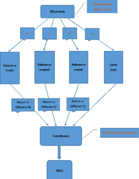
When the network is built up, it works as the following orders: 1) Blind node periodically broadcasts different information, each reference node (or the coordinator) receives the signal; 2) Each reference node (or the coordi-nator) judges whether the received information matches, if the signal matches, reference node (or the coordina-tor) responses and generates a RSSI, if the signal doesn’t match, reference node (or coordinacoordina-tor) doesn’t re-sponse; 3) The generated RSSI transfers back to coordinator. If it is the coordinator which receives the signal, the backhaul instruction will not be executed and the RSSI will be directly stored in coordinator; 4) Different reference node uses the different ID numbers to send RSSI back to coordinator so that coordinator can judges which one send RSSI back by the number of the ID; 5) Blind node continuously sends different data in circle, reference nodes response in sharing time way in order to avoid congestion and packet loss, each reference node (or the coordinator) generates the RSSI, and every four RSSI is in a group. According to the RSSI of each group, coordinator operates the positioning program to calculate blind node’s position.
[image:2.595.209.441.403.701.2]The schematic diagram of wireless sensor networking on ZigBee which is used to send and receive data is shown as Figure 1. This figure shows the corresponding relationship of data’s transmission between nodes. And ZigBee hardware network is shown as Figure 2.
Figure 2. ZigBee Hardware network.
2.2. Positioning Algorithm in 3D Space
The ranging technique on ZigBee uses the principle of the radio signals’ regular attenuation with distance to measure the distance between the nodes. The relationship between RSSI and transmission distance is shown as following:
(
10 lg)
RSSI= − × ×n d+A
In the formula, n represents the propagation coefficient of signal; d represents the distance to the sender; A
represents the signal’s strength in a distance of 1 m to the sender. The actual value of A and n have a great in-fluence on the level of ranging accuracy. A is an empirical parameter. We can get it by measuring the RSSI in a distance of 1 m to the sender. n is a parameter which is used to describe the relationship that the signal strength increases with decreasing distance, the value of n depends on the environment. To get the most proper value of n, we can set up the reference nodes first, and then try to use the different value of n to find the value of n which suits the environment most.
After the above analysis, we obtain a linear relationship between the RSSI and distance’s algorithm. However, in the actual environment, this relationship does not satisfy well. RSSI is strongly influenced by electromagnetic environment surrounding nodes which also has its own Gaussian noise. Therefore, if we want to get the useful information, we have to take effective digital processing measures.
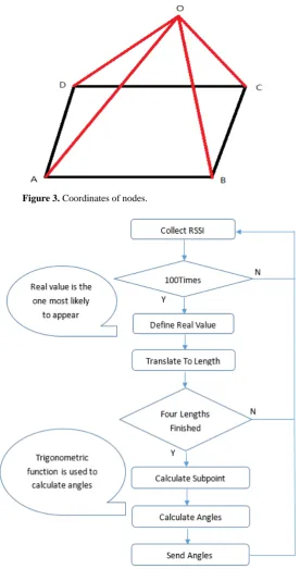
In the algorithm, at first we will store the RSSI every time we collect and get an average value that is a high-er-order moving average filtering. On the second, compare this mean with the empirical values stored in the ta-ble and repeatedly counting. If the RSSI value is close to the value of the tata-ble, we will count on the position once. After we continuously record until N times, check the result of the counting, if one of these values is big-ger than a number M, we consider the possibility of this point’s appearance is the biggest. Reset the value of N and M so that we can make sure the point’s appearance, and a round of collection was finished, then we send the RSSI of this node to the coordinator. This algorithm is based on the distribution of the RSSI; it makes the value whose frequency of appearance is the biggest as a credible one so that we can greatly reducing the electromag-netic interference. But, RSSI value is always changing in a big range because of electromagelectromag-netic influence, and pack loss also reduces the speed of distance calculation. So, we need to wait for several second until the system figure out distance of target.
L. Zhang et al.
Y. According to the theory of space analytic geometry, the angle of the blind node can be obtained for tracking. Flowchart of coordinates calculation based on RSSI is shown as Figure 4.
2.3. Orientation Platform
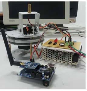
[image:4.595.179.456.183.707.2]The hardware platform of the design is a PTZ which is controlled by two servos which (angle controllable digi-tal servos) control the PTZ’s movement in horizondigi-tal and vertical planes. The upper end of the PTZ is equipped with a laser as shown in Figure 5. And Figure 6 shows the flowchart of orientation platform.
Figure 3. Coordinates of nodes.
Figure 5. PTZ with laser.
2.3. Complete Hardware System
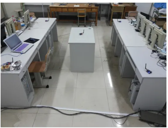
After ZigBee network complete the positioning, MCU will transfer the real time data to the microcontroller which will deal with the data, and then converts the position information to two PWM signals. We send the sig-nals to the two servos so that we can control the PTZ rotation angle in the horizontal and vertical planes. Be-cause the positioning system works in indoor environment, we place the PTZ in a corner of room, so we can achieve full coverage of interior space in a combination of two servos by using only rotation angle of 90 degrees of each servo and laser can align to the blind node in the space. When the position of the blind node changes the data generated also changes, servos rotate and laser aligns again. Control platform’s entire structure is shown as Figure 7.
3. Conclusion and Future Work
This paper proposed and implemented a design based on ZigBee which can locate and align in an automatic way. It effectively solves the problem of the indoor positioning and alignment in three-dimensional space. In posi-tioning network, the networking mode on ZigBee is flexible and operational with the characteristics of low cost and low power consumption, it can transfer and process real time data and ensure the reliability of data at the same time. In positioning algorithm, we focus on practical performance and it is more operational also, in a spe-cific indoor environment, it can realize the position of one point and ensure the accuracy at the same time. Two servos controlled PTZ can realize the alignment at any point in three-dimensional space within the interior of full coverage. The experiment’s results show that the design of this system can achieve the positioning and alignment under automatic control.
L. Zhang et al.
Figure 6. Flowchart of orientation platform.
Figure 7. Hardware system design.
Acknowledgements
This work was supported by “South Korea study interdisciplinary collaborative innovation platform project”, Shandong University (Weihai), China.
References
[image:6.595.171.458.376.594.2]and Parallel/Distributed Computing, 2008. SNPD ‘08. http://dx.doi.org/10.1109/SNPD.2008.125
[2] Kaemarungsi, K., Ranron, R. and Pongsoon, P. (2013) Study of Received Signal Strength Indication in ZigBee Loca-tion Cluster for Indoor LocalizaLoca-tion. 10th International Conference on Electrical Engineering/Electronics, Computer,
Telecommunications and Information Technology.
[3] The ZigBee Alliance Website. http://www.zigbee.org
[4] Kuo, W.-H., Chen, Y.-S., Jen, G.-T. and Lu, T.-W. (2010) An Intelligent Positioning Approach: RSSI-Based Indoor and Outdoor Localization Scheme in Zigbee Networks. 2010 International Conference on Machine Learning and
Cy-bernetics (ICMLC), Volume 6.
[5] Wheeler, A. (2006) ZigBee Wireless Networks for Industrial Systems—White Paper, Ember Corp.
[6] Zhang, J.W., Zhang, L., Ying, Y. and Gao, F. (2009) Research on Distance Measurement Based on RSSI of ZigBee.
Chinese Journal of Sensors and Actuators, 22.
[7] Zhong, D.X., Ji, W., Liu, Y.L., Han, J.Q. and Li, S.B. (2011) An Improved Routing Algorithm of Zigbee Wireless Sensor Network for Smart Home System. Proceedings of the 5th International Conference on Automation, Robotics
and Applications, Wellington, 6-8 December 2011.
[8] Bras, L., Oliveira, M., de Carvalho, N.B. and Pinho, P. (2010) Low Power Location Protocol Based on ZigBee Wire-less Sensor Networks. 2010 International Conference on Indoor Positioning and Indoor Navigation (IPIN), ZUrich, 15-17 September 2010.http://dx.doi.org/10.1109/IPIN.2010.5647869
[9] Liu, H., Darabi, H., Banerjee, P. and Liu, J. (2007) Survey of Wireless Indoor Positioning Techniques and Systems.
IEEE Transactions on Systems, Man, and Cybernetics, Part C: Applications and Reviews, 37, 1067-1080.
[10] Liu, H., Kshirsagar, A., Ku, J., Lamb, D. and Niederberger, C. (2005) Computational Models of Intracytoplasmic Sperm Injection Prognosis. Proc. 13th Eur. Symp. Artif. Neural Netw., Bruges, April 2005, 115-120.