© 2015, IRJET ISO 9001:2008 Certified Journal
Page 641
SEISMIC EVALUATION OF MULTI-STOREY R.C. STRUCTURE USING
DIFFERENT FLOOR DIAPHRAGMS
Rahul Chourasiya
1, Rashmi Sakalle
21
Student, Civil Engineering, Truba Institute of Engineering and Information Technology, M.P., Bhopal, India
2Asst. Prof., Civil Engineering, Truba Institute of Engineering and Information Technology, M.P., Bhopal, India
---Abstract-
In this study, seismic analysis of multi storeyRC building frames have been carried out considering different types of floor diaphragm. Floor diaphragm systems are very efficient in resisting lateral forces. STAAD. Pro software has been used for analysis purpose. Analyses of multi storey RC building frames are carried out in building frame with floor diaphragm. Three different type of floor diaphragm are used i.e. without diaphragm, semi rigid diaphragm and rigid diaphragm. Results are collected in terms of maximum moments in beams, axial force, shear force, maximum displacement and storey displacement which are critically analysed to quantify the effects of various parameters. This approach focuses on the different type of floor diaphragm nature in a structure and their effectiveness in reducing the lateral displacement and moment ultimately to achieve economy in construction with similar structural frames
Key words
:
Seismic, Floor diaphragm, Maximummoment, Shear Force, Storey displacement, Peak storey displacement
1. INTRODUCTION
Multi-storey buildings are a special class of structures with their own peculiar characteristics and necessities. Multi-storey buildings are occupied by a massive amount of population. Therefore, their accident and devastation can have very serious consequences on the life and economy. The intention of this study is therefore, to investigate the effect of buildings in various seismic zones performance by comparing it with rigid diaphragm, semi-rigid diaphragm and without diaphragm. The limit states design philosophy is the universally accepted philosophy, which is based on semi probabilistic approach for both structural properties
and loadingconditions. In this work we use STAAD Pro V8i
which is one of the most popular structural engineering
software products for 3D model generation, analysis and
design. Some of the prominent literature on the topic are as follows
-Wakchaure M.R and Ped S. P (2012) analysed the effect of masonry walls on high rise building is studied. A various arrangements are analysis in linear dynamic is carried out. G+9 R.C.C. framed building is modelled for the analysis. Earthquake time history is applied to the framed building and various cases of analysis are taken. Approach to analyse this work is software (ETABS). Analysis is calculated and comparative result of all the models on the basis of various parameters like beam forces, column forces and displacements.
Kai Hu, et al. (2012) concluded that, the traditional software can no longer meet the needs of calculation and analysis. In this work, different type of analysis method is used by dynamic analysis were executed using in-house developed software.
Liang Chen and Lucia Tirca (2012) investigates the inelastic behaviour of the 4, 8 and 12 storey elastic zipper braced frame (E-ZBF) buildings located in a high risk seismic zone (Victoria, BC) under crustal, subduction, and near-field ground motion ensembles.
Rana Roy and Sekhar Chandra Dutta (2010) recognized that inelastic response for short period systems is very sensitive to reduction factors (R) and may be phenomenally amplified even for small R due to soil– structure interaction implying restrictive applicability of dual-design philosophy. Buildings shows that inelastic response of the asymmetric structure relative to its symmetric counterpart is not appreciably influenced due to soil structural interaction. The work also shows that equivalent single storey model characterised by the lowest period rather than the fundamental one of the real system tends to yield conservative estimation of inelastic demand at least for the short-period systems.
© 2015, IRJET ISO 9001:2008 Certified Journal
Page 642
of the floor mass; transfer forces which develop from theinteraction of lateral force resisting elements with different displacement patterns, such as wall and frame elements; and difference of transfer forces due to different strengths and stiffness of the structural elements. The magnitude and trends of forces in the floor diaphragms have been determined using 2-dimensional in elastic time history analysis.
Ho Jung et al. (2007) discussed a simple method to more accurately estimate peak inter storey drifts that accounts for higher mode effects described for low-rise perimeter shear wall structures having flexible diaphragms or even for stiff diaphragms.
Wilkinson and Hiley (2006) analysed a materially non-linear plane-frame model subjected to earthquake forces. Storey of the building by an assembly of vertical and horizontal beam elements The model introduces yield hinges with ideal plastic properties in a regular plane frame. The displacements were described by the sway of each floor and the rotation of all beam–column intersections. Thus, the study go on with static condensation of the dynamic equations for the translations.
Vipul Prakash (2004) gives the prospects for Performance Based Engineering (PBE) in our country. He records the pre-requisites that made the emergence of PBE possible in country of California, the criteria for earthquake resistant design of structures are given the Bureau of Indian Standards (BIS). IS 1893-2002 reduced the number of seismic zones to four by merging zone I with zone II and adopted a modified CIS-64 scale for seismic zoning.
Aim for this study is to understand the effect of seismic in multi storey structure and the remedial measures to control these effects. To do this, models are generated and analysed with the help of STAAD.Pro software, and the effect of floor diaphragm pattern to resist the seismic forces are critically analysed.
2. METHODOLOGY
Following steps have been adopted in this study- Step-1 selection of building geometry, bays and story Step-2 Selection of diaphragm (Rigid diaphragm, semi-rigid and without diaphragm)
Step-3 selection of 4 seismic zones (II,III,IV and V) Step-4 Formation of load combination (13 load combinations)
Table 1- Load case details
Step-5 Modelling of building frames
Step-6 Analysis considering different diaphragm models, seismic zones and each load combinations
Step-7 Comparative study of results in terms of maximum moments in columns and beams, base shear, story displacement, peak story displacement.
3. STRUCTURAL MODELLING AND ANALYSIS
CASE-01: Bare frame without diaphragm of G+7 storey height.
CASE-02: Building frame with rigid diaphragm of G+7 storey height.
CASE-03: Building frame with semi-rigid diaphragm of G+7 storey height.
3.1 Diaphragms
According to
Paulay and Priestley (1992), the
interaction of the lateral load with
lateral-force-resisting vertical elements is achieved by the use of floor systems that generally possess large in-plane stiffness. Thus, the vertical load resisting elements will contribute to the total lateral load resistance in proportion to their own stiffness. Floors can act as diaphragm because of its large in-plane stiffness. The main function of the floorLoad case no. Load cases details
1. E.Q. IN X DIR.
2. E.Q. IN Z DIR.
3. DEAD LOAD
4. LIVE LOAD
5. 1.5 (DL + LL)
6. 1.5 (DL + EQX)
7. 1.5 (DL - EQX)
8. 1.5 (DL + EQZ)
9. 1.5 (DL - EQZ)
10. 1.2 (DL + LL + EQX)
11. 1.2 (DL + LL - EQX)
12. 1.2 (DL + LL + EQZ)
© 2015, IRJET ISO 9001:2008 Certified Journal
Page 643
diaphragm is to transmit the inertial forces generated bythe ground motion of the floor mass at a given level to the lateral-force-resisting vertical elements generated by the ground motion. At lower story, significant lateral load need to be transferred from one element to another element causing significant shear forces and bending moments in the diaphragm.
3.2 Types of diaphragms
Floor and roof systems act as a diaphragm to transfer the lateral load to the vertical load supporting elements like beams, columns, walls etc. For the simplicity in the dynamic analysis of building, floors are assumed to be rigid in their own plane. This concept was developed 40 years ago which assumes that the whole floor moves as the rigid body motion; two translational and one rotational degree of freedom per each floor. This assumption is valid for many buildings but not valid for long, narrow or irregular buildings. Blume et al. conducted forced-vibration tests on several school buildings and reported long natural periods of roof or floor diaphragms.For the analysis purpose, diaphragm can be classified as rigid, semi rigid or semi flexible and flexible based on the relative rigidity.
3.2.1 Rigid diaphragm
In the rigid floor diaphragm, the lateral forces are distributed to the vertical load resisting elements (frames, shear walls) in proportion to their relative stiffnesses. In the rigid diaphragm concept, the in-plane displacement is considered to be equal along its entire length under lateral load. This rigid diaphragm concept is reasonable for building nearly square in plan. A case-in-plane concrete floor is an example of rigid diaphragm.
3.2.2 Semi-rigid diaphragm
In reality, the diaphragm can neither be perfectly rigid nor be perfectly flexible. However, in order to simplify the analysis with reasonable assumptions, the semi-rigid diaphragm can be made as to a diaphragm's rigidity or flexibility but in some cases the diaphragm deflection and the vertical lateral load-resisting (VLLR) elements can be of same magnitude only in semi-rigid diaphragm. The absolute size and stiffness are important in diaphragm but that is not the final determining factor whether it will behave as rigid, flexible, or semi-rigid. In rigid diaphragm, such as steel deck, is partly able to distribute the lateral
forces into the VLLR elements based on their relative stiffness.
[image:3.612.341.550.243.400.2]Semi-rigid or semi-flexible diaphragms are those which have significant deflections under load, but which also have sufficient stiffness to distribute a portion of the load to the vertical elements in proportion to the rigidities of the vertical resisting elements. The action is analogous to a continuous beam system of appreciable stiffness on yielding supports. The support reactions are dependent upon the relative stiffness of both diaphragm and the vertical resisting element.
Figure 1- Isometric view of a basic building structural system comprising horizontal spanning elements (diaphragms), vertical spanning elements (walls and frames), and foundation
Figure 2- Role and action of diaphragm
[image:3.612.343.555.486.636.2]© 2015, IRJET ISO 9001:2008 Certified Journal
Page 644
Structural models for different cases are shown in Figure 3 [image:4.612.413.518.113.353.2]to 6
Figure 3- Plan of Bare frame
[image:4.612.44.262.136.340.2]Figure 4- Structural model of Bare frame
Figure 5- A typical isomeric diagram for diaphragm
Figure 6- A typical plan diagram for diaphragm
The column size is of 450MM x 450MM, and the beam size is 230MM x 450MM.
5. MATERIAL AND GEOMETRICAL PROPERTIES
Following material properties have been considered in the modelling - [image:4.612.74.255.380.630.2] [image:4.612.373.557.404.595.2]© 2015, IRJET ISO 9001:2008 Certified Journal
Page 645
Density of Masonry: 20 kN/m3 (Assumed)Young's modulus of concrete: 5000 Poisson'sratio: 0.17
The foundation depth is considered at 2.0m below ground level and the typical storey height is 3.0 m.
Loading conditions
Following loadings are considered for analysis - (a) Dead Loads: as per IS: 875 (part-1) 1987
Self wt. of slab considering 150 mm thick. Slab = 0.15 x 25 = 3.75 kN/m2 (slab thick. 150 mm assumed)
Floor Finish load = 1 kN/m2
Water Proofing Load on Roof = 2.5 kN/m2
Masonry Wall Load = 0.25 x 2.55 x 20 = 12.75 kN/m (b) Live Loads: as per IS: 875 (part-2) 1987
Live Load on typical floors = 2 kN/m2 Live Load on Roof = 1.5 kN/m2 (c) Earth Quake Loads:
All the building frames are analyzed for 4 seismic zones The earth quake loads are derived for following seismic parameters as per IS: 1893 (2002) [21]
a. Earth Quake Zone-II,III,IV,V (Table - 2)
b. Importance Factor: 1 (Table - 6)
c. Response Reduction Factor: 5 (Table - 7)
d. Damping: 5% (Table - 3)
e. Soil Type: Medium Soil (Assumed)
f. Period in X direction (PX): seconds Clause 7.6.2
g. Period in Z direction (PZ): seconds Clause 7.6.2
Where h = height of the building
dx= length of building in x direction dz= length of building in z direction
6. RESULTS AND DISCUSSION
The results are discussed in bracing system and diaphragm system
6.1 Diaphragm models
Results can be described under following heads -
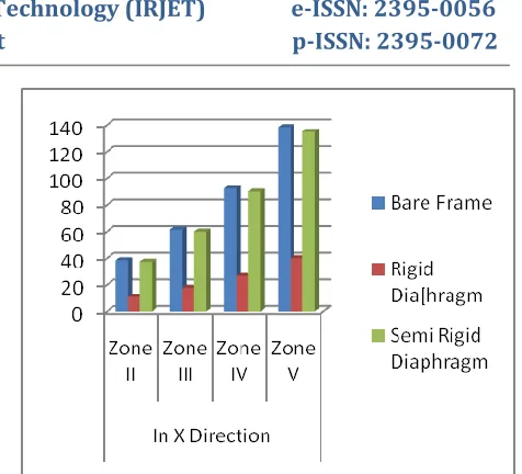
Table 2- Maximum displacement in diaphragm system Maximum displacement
Structure
type Zone II Zone III Zone IV Zone V
Bare Frame 38.465 61.488 92.186 138.232
Rigid
Diaphragm 11.074 17.718 26.577 39.865
Semi Rigid
[image:5.612.38.583.54.692.2]Diaphragm 37.434 59.894 89.842 134.762
[image:5.612.328.566.63.279.2]Fig. 7- Maximum displacement in diaphragm system
Table 3- Maximum bending moment in diaphragm system Structure
type Zone II Max Bending Moment Zone III Zone IV Zone V
Bare Frame 137.728 187.212 253.191 366.537
Rigid
Diaphragm 65.779 105.246 157.869 236.803
Semi rigid
Diaphragm 135.768 184.114 248.575 358.501
Figure 8-Maximum bending moment in diaphragm system
Table 4- Maximum shear force in diaphragm system Structure
type Zone II Zone III Zone IV Max Shear force Zone V Bare
Frame 115.938 141.473 175.52 226.59
Rigid
[image:5.612.327.589.306.601.2]© 2015, IRJET ISO 9001:2008 Certified Journal
Page 646
Semi rigid [image:6.612.35.572.55.574.2]Diaphragm 114.929 139.875 173.137 223.031
Figure 9- Maximum shear force in diaphragm system
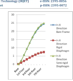
Table 5- Max. storey displacement in zone-II in diaphragm system
Max story displacement in structure in zone-II Floor Frame Bare Diaphragm Rigid Diaphragm Semi rigid
Base 0 0 0
Ground
Floor 2.088 0.954 2.13
1st Floor 5.565 1.941 5.667
2nd Floor 9.239 2.944 9.418
3rd floor 12.828 3.937 13.096
4th floor 16.184 4.888 16.546
5th floor 19.162 5.758 19.619
6th floor 21.608 6.5 22.144
7th floor 23.362 7.061 23.945
8th floor 24.378 7.382 24.956
Figure 10-Max. storey displacement in zone-II in diaphragm system
Table 6- Max. storey displacement in zone-III in diaphragm system
Max story displacement in structure in zone-III Floor Frame Bare Diaphragm Rigid Diaphragm Semi rigid
Base 0 0 0
GF 3.341 1.527 3.408
1st Floor 8.903 3.106 9.067
2nd Floor 14.782 4.71 15.07
3rd floor 20.525 6.299 20.953
4th floor 25.894 7.821 26.474
5th floor 30.66 9.213 31.391
6th floor 34.572 10.4 35.43
7th floor 37.379 11.298 38.311
[image:6.612.320.577.63.347.2] [image:6.612.35.302.65.334.2] [image:6.612.324.595.407.570.2]© 2015, IRJET ISO 9001:2008 Certified Journal
Page 647
Figure 11- Max. storey displacement in zone-III indiaphragm system
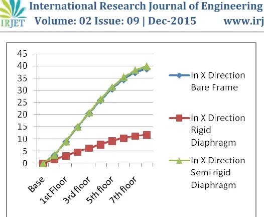
Table 7- Max. storey displacement in zone-IV in diaphragm system
Max story displacement in structure in zone-IV
Floor Bare In X Direction
Frame Diaphragm Rigid Diaphragm Semi rigid
Base 0 0 0
GF 5.012 2.29 5.112
1st Floor 13.355 4.659 13.601
2nd Floor 22.174 7.066 22.604
3rd floor 30.788 9.449 31.43
4th floor 38.841 11.732 39.711
5th floor 45.99 13.819 47.086
6th floor 51.858 15.6 53.146
7th floor 56.069 16.947 57.467
8th floor 58.508 17.718 59.894
[image:7.612.38.301.61.277.2]Figure 12- Max. storey displacement in zone-IV in diaphragm system
Table 8- Max. storey displacement in zone-V in diaphragm system
Max story displacement in structure in zone-V
Floor Bare In X Direction
Frame Rigid Diaphragm Diaphragm Semi rigid
Base 0 0 0
GF 7.517 3.435 7.669
1st Floor 20.033 6.989 20.402
2nd floor 33.26 10.598 33.907
3rd floor 46.182 14.173 47.144
4th floor 58.262 17.597 59.567
5th floor 68.985 20.729 70.63
6th floor 77.787 23.4 79.718
7th floor 84.103 25.42 86.201
8th floor 87.759 26.577 89.842
Figure 13- Max. storey displacement in zone-V in diaphragm system
7. CONCLUSION
Following are the salient conclusions of this study-
From the present study it is seen that rigid diaphragm is much efficient in compared to other diaphragms system in
reducing moment, storey displacement, peak
[image:7.612.324.582.143.574.2] [image:7.612.27.559.211.724.2]© 2015, IRJET ISO 9001:2008 Certified Journal
Page 648
semi rigid diaphragm structure. And semi rigid diaphragmand without diaphragm produces more displacement, shear force and moments than the rigid diaphragm models. And rigid diaphragm reduces displacement thrice, moment twice and shear force almost one and half means it helps in reducing frame section and area of steel. So, It has been observed from the analysis of various building the rigid diaphragm is more effective. It is concluded that the building with rigid diaphragms will be structurally economic resulting into a great deal of saving in reinforcement steel.
REFERENCES
Coull A. & SmithE.stafford, Tall Buildings, with particular reference to shear wall structures, Pergamon Press, 1967. Barron M. Joel and Hueste Beth D. Mary, Diaphragm Effects in Rectangular Reinforced Concrete Buildings, ACI Structural Journal, October 2004, pp. 615-624.
Bull D.K., Understanding the Complexities of Designing Diaphragms in Buildings for Earthquakes, Bulletin of the New Zealand Society for the Earthquake Engineering 37(4), June 2003.
Chen Sheng-Jin, Huang Ti, Lu Le-Wu, Diaphragm Behaviour of Reinforced Concrete Floor Slabs, Proceedings of ninth world conference on Earthquake Engineering, Tokyo Japan, August 1988.
Chopra, A. K., Dynamics of Structures: Theory and Applications to Earthquake Engineering, Prentice-Hall. Inc., Englewood Cliffs, New Jersey, 1995.
Clough Ray W., Joseph Penzien, Dynamics of structures, McGraw-Hill, New York, 1993.
Danay A., A general element for analysis of asymmetric multi-storey buildings with varying cross-section, Building and Environment, 11 (1), 1976, pp. 57–67.
Dong-Guen Lee, Hyun-Su Kim, Min Hah Chun, Efficient seismic analysis of high-rise building structures with the effects of floor slabs, Engineering Structures, 24(5) May 2002, pp. 613-623.
GardinerD. R., Bull D.K., Carr A. J., Internal forces of concrete floor diaphragms in multi-storey buildings, New Zealand Society Earthquake Engineering Conference, Paper No. 21, 2008.
Hawary-El M. M., Effect of horizontal diaphragm flexibility on the P-delta analysis,Published by Elsevier Ltd, 53(6), December 1994, pp. 1275–1280.
Ho Jung Lee, Mark A. Aschheim, Daniel Kuchma, Interstory drift estimates for low-rise flexible diaphragm structures, Engineering Structures, 29(7) 2007, pp. 1375-1397. http://en.wikipedia.org/wiki/Seismic_analysis
IS 1893 : 2002, Indian Standard criteria for earthquake resistant design of structures, Part 1 General provisions
and buildings, Draft of Fifth Revision, Bureau of Indian Standards, New Delhi, 2002.
Kai Hu, Yimeng Yang, Suifeng Mu, Ge Qu , Study on High-rise Structure with Oblique Columns by ETABS, SAP2000,
MIDAS/GEN and SATWE, Procedia
Engineering, 31, 2012, pp. 474-480.
SivakumaranK.S. and BalendraT.,Seismic analysis of asyMMetric multistorey buildings including foundation interaction and P-Δ effects, Engineering Structures, 16(8), November 1994, Pages 609–624.
Kunnath S., Panahshahi N., and Reinhorn A., Seismic Response of RC Buildings with Inelastic Floor Diaphragms, Journal of Structural Engineerin, 117(4), April 1991, pp. 1218–1237.