© 2017, IRJET | Impact Factor value: 5.181 | ISO 9001:2008 Certified Journal | Page 2794
Performance Analysis of Iterative Closest Point (ICP) Algorithm using
Modified Hausdorff Distance
Arunava Seal
1, Abhijit Bhowmick
21
School of Electronics Engineering, VIT University, Vellore, India
2Assistant Professor (Selection Grade), VIT University, Vellore, India
---***---Abstract -
Registration, tracking and reconstruction of 3-Dmodels in real time has many applications in the fields of pose estimation, alignment, motion estimation, object recognition, handheld scanning and augmented reality. Many varied techniques and approaches have been used to tackle the problem of registration and reconstruction of 3-D images. Our work aims to design a method for accurate and computationally efficient registration of 3-D shapes, through comparison and application of various alignment techniques. The expected outcome is a system able to align and reconstruct geometrically precise complex 3-D models in a fast and efficient manner. We mainly focus on the Iterative Closest Point Algorithm, which is the most popular method used in this field through many different forms and variations. An effort has been made to analyze these various forms which are used for object registration through the use of Modified Hausdorff Distance (MHD). Usage of outlier removal methods such as Random Sampling Consensus (RANSAC) and accelerating techniques such as kd-Tree search are also studied. This system could act as a foundation for implementing the ICP algorithm along with depth images or Simultaneous Localization and Mapping (SLAM).
Key Words: Iterative Closest Point(ICP), Object Modeling,
Object Alignment, Pose Estimation, 3-D Registration, Modified Hausdorff Distance
1. INTRODUCTION
In recent years digitization of physical objects has become easy with the growing popularity of 3D scanners. Scanners use laser, light or x-rays to form a point cloud defining the shape of the object being scanned. Registration is useful in comparing two scans taken at different time/conditions and is also helpful in combining the information in two scans into a single one. This paper aims to design a method for accurate and computationally efficient registration of 3-D shapes; the expected outcome being a system able to align and reconstruct geometrically precise complex 3-D models as efficiently as possible. The Iterative Closest Point Algorithm of Besl and Mckay is one of the most popular method used for rigid transformation of roughly aligned data sets. It is widely used for the registration of free form surfaces where dense data is assumed, and a good initial estimate is available or can be easily estimated. The ICP algorithm has become the dominant method for aligning three dimensional models based purely on the geometry, and sometimes color,
of the meshes. This system has been used for registering the outputs of 3D scanners, which typically only scan an object from one direction at a time. ICP starts with two meshes and an initial guess for their relative rigid-body transform, and iteratively refines the transform by repeatedly generating pairs of corresponding points on the meshes and minimizing an error metric. Many different variants of ICP have been utilized over the years for different purposes. We aim to analyze these variants and their performance and accuracy parameters in terms of Modified Hausdorff Distance which gives us a measure of the similarity between two-point sets. The initial part of the work entails the alignment of 3D models using the various ICP algorithms and optimization. We utilize the basic ICP model for different point data sets and analyze the shortcomings and scope for improvement. Based on that, we optimize the algorithm for efficiency and performance.
1.1 Related Work
© 2017, IRJET | Impact Factor value: 5.181 | ISO 9001:2008 Certified Journal | Page 2795
ICP(SICP) and Generalized ICP (GICP), Of these, CICP, PICP and TICP vary from the original ICP algorithm (denoted as OICP for the rest of this paper) in the first step of the algorithm: choosing correspondence points in the two data sets. The OICP algorithm did not impose any restrictions on corresponding point search; it considered every point in the scene surface for closest point calculation. However, for speeding up the convergence there has been a lot of interest regarding selection of points used for estimating transformation vectors. Trimmed ICP or TICP [8] selects only a predefined number of estimated matched pairs based on some given criterion. Picky ICP or PICP [9] rejects all points previously estimated to correspond to one reference point except one with the smallest distance. Comprehensive ICP or CICP [7] uses an enhanced implementation of the ICP algorithm using a comprehensive look-up matrix to find the best correspondence pairs.
Other ICP variants have come about as a result of negating the various drawbacks of the original algorithm of Besl and Mckay. Non-Rigid ICP [10] extends the ICP framework to non-rigid restoration, using an adjustable stiffness parameter, while retaining the convergence properties of the original algorithm. Scaling ICP or SICP [11] integrates a scale matrix with boundaries into the original ICP algorithm for scaling registration. Generalized ICP or GICP [12] combines the ICP and point-to-plane ICP algorithms into a new single probabilistic framework. This allowed for far greater robustness than the standard ICP approach. The latest techniques include Learning Anisotropic ICP, Weighted Average ICP, and ICP using Bi-unique Correspondences. Learning Anisotropic ICP (LA-ICP) [13] presents an online learning approach to 3D object registration that vastly improves the performance of Iterative Closest Point (ICP) methods. Weighted Average ICP (WA-ICP) [14] uses a new weighting approach to establish correspondence. ICP using Bi-Unique Correspondences [15] guarantees the uniqueness of corresponding pairs by searching multiple closest points. The latest trend in the field of 3D object registration and modeling is the use of RGB-D cameras which capture RGB images along with per-pixel depth information. This has been facilitated mainly by the increasing cheapness and availability of such cameras to the general public. RGB-D allows for greater resolution than Laser scanning but at the cost of reduced accuracy. An in-depth look into using depth cameras for 3D modelling in conjunction with using the ICP algorithm can be found in the work of Peter Henry et al in the field of RGB-D mapping [16]. It utilizes a novel joint optimization algorithm combining both matching using visual features and shape alignment. Sparse feature detection is carried out on the RGB images using a Scale Invariant Feature Transform (SIFT) feature detector and extractor. Random Sampling Consensus or RANSAC is used to find the best rigid transformation between the obtained feature sets. Then the ICP algorithm is carried out on the dense point clouds obtained from the depth data. The two results obtained are properly weighted and added to give us a finely refined 3D model of the indoor environment, which would not be
possible using a single approach. Several others have tried to carry forward with the work done in this paper with some newer and interesting approaches [17] [18] [19] [20]. A team comprising of several researchers at Microsoft also have used the depth sensors present in the Xbox Kinect camera to create KinectFusion. [21], which enables a user holding and moving a standard Kinect camera to rapidly create detailed 3-D environments of an indoor scene. The depth data is used to track the 3D pose of the sensor and recreate the precise 3D models of the scene in real-time due to the use of a novel GPU based pipeline. The work done by the KinectFusion team does not require any explicit feature detection and in fact allows for user interaction with dynamically changing scenes. This allows for some exciting new usages in the field of low-cost handheld scanning, object segmentation through direct interaction and in the field of Geometry Aware Augmented Reality. Further progress in this particular project was made by the team of Qin Ye, where they further improved upon the KinectFusion algorithm by combining epipolar constraints with point-to-point constraints. [22]
Our work combines the work of [7] using the Comprehensive ICP (CICP) algorithm in conjunction with RANSAC which has not been done before. Also, we have identified Modified Hausdorff distance, described in detail in [23] as a parameter for analyzing our observations along with the usual parameters such as number of iterations and computation time. Thus, we have come to conclusions regarding our alignment performance through a novel approach that has not been implemented before.
2. THEORY
2.1 The ICP Algorithm
First let us take a look at the Iterative Closest Point (ICP) Algorithm. The ICP algorithm is a general-purpose, representation-independent method for the accurate and computationally efficient registration of 3-D shapes including free form curves and surfaces. Its main application is to register digitized data from unfixtured rigid objects with an idealized geometric model prior to shape detection. The basic tenets of the ICP algorithm are:
• Can be used for efficient registration of 3D shapes • Allows for full six degrees of freedom (6DOF) • Independent of shape representation. • Given “model” shape; Sensed “data” shape
• Algorithm requires no extraction of features, no curve or surface derivatives, no pre-processing of 3D data (except for removal of statistical outliers) • Always converges monotonically to the nearest local
minimum of a mean square distance metric • Works best when we already have an initial estimate
of the relative pose.
© 2017, IRJET | Impact Factor value: 5.181 | ISO 9001:2008 Certified Journal | Page 2796
Principle: A data shape P is moved through translationand rotation to be in best alignment with a model shape X.
STEPS OF THE ICP ALGORITHM:
Chart -1: Flowchart describing the different steps of ICP algorithm
Several other variants of the original ICP (OICP) algorithm have also been used in recent times in for several different variations and for different applications. Some of the more popular ones are-
CICP: Enhanced implementation of the ICP algorithm using a comprehensive look-up matrix to find the best correspondence pairs. It results in reducing the minimum MSE between the two data sets after registration.
TICP: Selects only a predefined number of estimated matched pairs based on some given criterion.
PICP: Rejects all points previously estimated to correspond to one reference point except one with the smallest distance.
SICP: Integrates a scale matrix with boundaries into the original ICP algorithm for scaling registration. The scale matrix is introduced directly
into the least squares problem with the constraint condition that the scale matrix is bounded. Non-Rigid ICP: Extending the ICP framework to
non-rigid restoration, using an adjustable stiffness parameter, while retaining the convergence properties of the original algorithm. This is extremely useful for registration of human faces or animals.
GICP: GICP developed at Stanford combines the ICP and point-to-plane ICP algorithms into a new single probabilistic framework. It utilises a new ‘plane-to-plane’ approach modelling the planar surface structure from both scans instead of just the model scans, which is the method followed in the typical ‘point-to-plane’ method. This allows for far greater robustness than the standard ICP approach.
2.2 Comprehensive ICP(CICP)
The CICP algorithm has been used extensively in our work hence a closer inspection of the algorithm is warranted. In the CICP algorithm, a novel effective evaluation matrix called a comprehensive look-up matrix was introduced for the purpose of correspondence search. This new method makes sure that each selected point on the scene surface has a definite and unique match in the reference surface.
In the original ICP algorithm, searching of correspondence of points is done based on a vector search approach within a P-M distance matrix as shown below in figure 2, where di,j is the distance between pi and mj. CICP differs in that it sorts the di,j distances in ascending order within the P-M distance matrix. Also, once either mj or pi has been assigned a correspondence, those points are no longer considered. This helps to ensure unique association between points in the scene surface and the reference surface. The algorithm can be summarized as follows, for model shape P and data shape X.
1. For each point pi € P (i=1,…,Np), compute Euclidian distance to each point mj € X(j=1,…,Nm). Then for Np times, loop:
a. Look for location (i,j) corresponding to minimum distance in the look up matrix b. Assign pi to mj as correspondence pair c. Remove this correspondence pair from
further consideration.
2. Compute the transformation parameters (R, T) and transform P accordingly.
3. Compute the MSE between reference and transformed data sets. If MSE is above a threshold and number of iterations k is less than maximum allowed number of iterations, new iteration starts, else the iterative procedure stops.
© 2017, IRJET | Impact Factor value: 5.181 | ISO 9001:2008 Certified Journal | Page 2797
2.3 Modified Hausdorff Distance(MHD)
Hausdorff distance (Huttenlocheret al. 1993) is a measure of similarity between two point sets. Its objective is to find out the greatest mismatch between two point sets. The biggest advantage of using Hausdorff distance over other parameters as a similarity metric is that it cannot be zero until both the sets are exactly matched.
Given two point sets P = {p1, p2 ,……, pn} and Q={q1,q2,…., qm}, the Hausdorff distance is defined as
[image:4.595.363.508.101.209.2] [image:4.595.309.557.290.652.2]
(𝑃, 𝑄) = max (h (P, Q), h (Q, P)), where h (P, Q) = ||p-q|| for max(p€P) min(q€Q)
Here h (P, Q) is the maximum value of the Forward Hausdorff distances (FHD), and h (Q, P) is the maximum value of the Reverse or Backward Hausdorff Distances (BHD). FHD is the set of distances of the nearest points in P for every point in Q and BHD is the set of distances of the nearest points in Q for every point in P.
Hausdorff Distance however is not very robust to outliers in the point maps. Thus, Dubuisson and Jain in 1994 proposed the Modified Hausdorff Distance (MHD).
MHD = max (mean (h (P, Q), mean (h (Q, P))
MHD is more robust to outliers and it increases monotonically as the similarity between the two data sets decreases. So, MHD has proven to be a better choice for a similarity metric.
2.4 Random Sampling Consensus (RANSAC):
Random sampling consensus or RANSAC is an iterative method to estimate parameters of a mathematical model from a set of observed data that contains outliers, when outliers not to be given any influence on the values of the estimates. Thus, it is basically an outlier detection method. RANSAC is a learning technique which estimates the parameters of a model through random sampling of observed data.
3. EXPERIMENTAL RESULTS
Using the MRPT library, we were able to generate objects, introduce an alignment error, and analyze the performance of ICP algorithm on these objects. Objects generated were a sphere and two concentric disks. Scans of the objects were performed by raytracing followed by conversion to point cloud format.
Fig -1:Generated Objects
Firstly, let us take a look at the result of ICP for a given alignment error (x displacement, y displacement, z displacement, yaw, pitch, roll) and the parameters used:
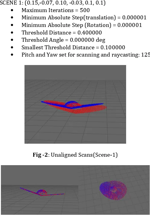
SCENE 1: (0.15,-0.07, 0.10, -0.03, 0.1, 0.1) Maximum Iterations = 500
Minimum Absolute Step(translation) = 0.000001 Minimum Absolute Step (Rotation) = 0.000001 Threshold Distance = 0.400000
Threshold Angle = 0.000000 deg Smallest Threshold Distance = 0.100000
Pitch and Yaw set for scanning and raycasting: 125
Fig -2:Unaligned Scans(Scene-1)
Fig -3: Scans aligned using CICP algorithm (Scene 1)
Results obtained from the above: Size of Scan 1: 1847 Size of Scan 2: 2390
ICP run took 0.017835 secs.
© 2017, IRJET | Impact Factor value: 5.181 | ISO 9001:2008 Certified Journal | Page 2798
No. of iterations= 73 MHD is: 0.0338736
Keeping the parameters constant including the size of the point sets M1 and M2, the experiment is repeated with two different and increasingly greater alignment errors and the results obtained are as follows:
[image:5.595.311.535.114.264.2]SCENE 2: (0.65, 0.15, 0.22, -0.65, -0.05, 0.15) SCENE 3: (1.5, 0.85, 1.50, 0.35, -1.5, -2.15)
Table-1: Analyzing performance of ICP for different alignments
Parameter Computation
Time No. Iterations of MHD
Scene 1 0.017835 73 0.0338736
Scene 2 0.06654 182 0.0367668
Scene 3 0.064447 244 0.0341597
[image:5.595.309.533.317.460.2]Next, we considered the precision of the scans and the effect it has on the computation time, iterations and MHD performance. While performing the scans of the 3D objects, two parameters YAW and PITCH are initialized and this indicates the precision of scanning. These parameters determine how accurately the scans of the 3-D objects are taken and this has a definite impact on the outcome of the algorithm.
Table -2: Analyzing different performance parameters with increase in precision of scans
PITCH and YAW value
Set Size for data set and model set
Computation
Time(secs) No. of Iterations MHD
50 M1: 291
M2: 371 0.000549 18 0.0833314
75 M1: 656
M2: 849 0.008814 46 0.0561693
100 M1: 1176
M2: 1526 0.012861 70 0.0417946
125 M1: 1847
M2: 2390 0.017835 73 0.0338736
150 M1: 2672
M2: 3458 0.039534 99 0.0287003
175 M1: 3637
M2: 4713 0.075907 123 0.0237184
200 M1: 4762
M2: 6154 0.108322 164 0.0210493
225 M1: 6035
M2: 7803 0.126281 164 0.0185829
250 M1: 7461
M2: 9637 0.160194 197 0.0165332
275 M1: 9036
M2:11676 0.198515 214 0.0150802
0 0.05 0.1 0.15 0.2 0.25
50 100 150 200 250
Fig -4: Graph showing computation time variance with increase in precision of scans (generated objects)
0 50 100 150 200 250
[image:5.595.31.305.478.747.2]50 100 150 200 250
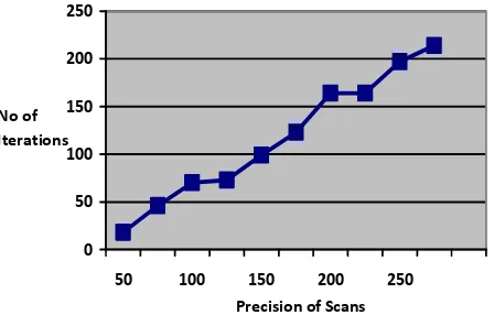
Fig -5: Graph showing variance of no of iterations with increase in precision of scans (generated objects)
0 0.01 0.02 0.03 0.04 0.05 0.06 0.07 0.08 0.09
50 100 150 200 250
Fig -6: Graph showing variance of MHD with increase in precision of scans (generated objects)
Three crucial inferences can be made from these observations:
• With increase in the precision of scans, the computation time for the algorithm increases, all other parameters remaining constant. This is to be
Precision of Scans
Precision of Scans
Precision of Scans Time(s)
No of Iterations
[image:5.595.321.531.516.662.2]© 2017, IRJET | Impact Factor value: 5.181 | ISO 9001:2008 Certified Journal | Page 2799
expected as the amount of data increases exponentially.
• With increase in the precision of scans, the number of iterations taken to reach convergence increases, all other parameters remaining constant. This is due to the increase in the depth of data available to the program.
• With increase in the precision of scans, MHD which is a measure of similarity between point sets decreases (Ideally MHD will be zero if the two point sets are identical). This is to be expected as more precision means more information about the two point sets are available. More data means a better approximation of rotation and translational vectors can be found, which translates to better alignment between the two point clouds.
Effect of Ransac:
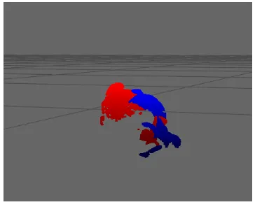
The effectiveness of RANSAC can be highlighted by implementing our ICP algorithm with and without RANSAC enable and noting the changes. In our case we have also enabled “Only Unique Correspondences” which imply all correspondences between the data set and the model set will be unique. Let us consider the scans obtained at 0 degrees and 45 degrees of the Stanford Bunny taken from the Stanford 3-D Scanning Repository.
[image:6.595.319.547.101.190.2]Fig -7: Scanned Models at 45 and 90 degrees of alignment
[image:6.595.69.253.427.568.2]Fig -8: Scans aligned without using RANSAC
Fig -9: Scans aligned using RANSAC
Table -3: Analyzing the effect of RANSAC on performance
Computation
Time(s) iterations No of MHD
Without
RANSAC 1.56418 132 0.0265503
With
RANSAC 3.16925 423 0.00471862
From the observations, we can easily infer that RANSAC helps in fine-tuning the alignment Although RANSAC takes considerably more
computation time and higher number of iterations, the performance is likewise much better.
This better performance is highlighted by the difference in MHD, where RANSAC enabled ICP shows a much lower MHD than ICP without RANSAC.
4. CONCLUSION
[image:6.595.70.252.599.747.2]© 2017, IRJET | Impact Factor value: 5.181 | ISO 9001:2008 Certified Journal | Page 2800
tested our algorithm in a special case where the data set is a subset of our model data, and found the algorithm to be working perfectly in such a situation as well. In future, we hope to build on the work done by incorporating our algorithm with RGB-D data to reconstruct environments and incorporate SLAM into our system.
ACKNOWLEDGEMENT
We would like to acknowledge Centre for Artificial Intelligence and Robotics (CAIR), an organisation of Defence Research and Development Organisation (DRDO) in Bangalore for allowing us to conduct this experiment at their laboratory. Also, we would like to acknowledge the Stanford University Computer Graphics Library for usage of the Stanford 3-D Scanning Repository of the Stanford University Computer Graphics Laboratory.
REFERENCES
[1] O.D. Faugeras and M. Hebert, “The representation, recognition and locating of 3-D objects”, International Journal of Robotics Res. Vol 5, no 3, pp 27-52, Fall 1986
[2] P. J. Besl, “Geometric modeling and computer vision”,
Proc. IEEE, vol.76, no 8, pp 936-958, Aug 1988
[3] B. Curless and M. Levoy, “A volumetric method for building complex models from range images”, ACM Trans. Graph, 1996
[4] P. J Besl and N.D. Mckay,”A method for registration of
3-D shapes”, IEEE Trans. Pattern Analysis and Machine Intelligence, 14:239-256, February 1995
[5] Yulan Guo et al. “An Integrated Framework for 3-D
Modeling, Object Detection, and Pose Estimation From Point-Clouds”, IEEE transaction on Instrumentation and Measurement, Vol. 64, Iss: 3, March 2015.
[6] S. Rusinkiewicz and M. Levoy, “Efficient Variants of the ICP Algorithm” in Proc. of the International Conf. on 3-D Digital Imaging and Modeling, Quebec City, Canada, 2001.
[7] A. Almhdie, C. Léger, M. Deriche and R. Lédée, “3D
Registration using a New Implementation of the ICP Algorithm Based on a Comprehensive Lookup Matrix” Pattern Recognition Letters, vol. 28, no. 12, pp. 1523-1533, 2007.
[8] D. Chetverikov, D. Svirko, D. Stepanov, P.Krsek, “The
Trimmed Iterative Closest Point Algorithm”,16th International Conference on Pattern Recognition, 2002
[9] T. Zinsser, J. Schmidt, H.Niemann, “A refined ICP algorithm for robust 3-D correspondence estimation”, IEEE International Conference on Image Processing, Spain, 2003
[10]Brian Amberg, Sami Romdhani, Thomas Vetter, “Optimal
Step Nonrigid ICP algorithms for Surface Registration”
[11]Shaoyi Du1, Nanning Zheng1, Shihui Ying2, Qubo You1,
Yang Wu1, “An Extension Of The ICP Algorithm Considering Scale Factor”
[12]Aleksandr V. Segal, Dirk Haehnel, Sebastian, Stanford
University, “Generalized ICP”
[13]Bhoram Lee and Daniel D. Lee,” Learning Anisotropic
ICP (LA-ICP) for Robust and Efficient 3D Registration”, 2016 IEEE International Conference on Robotics and Automation (ICRA) Stockholm, Sweden, May 16-21, 2016
[14]Rong Wang ,Zheng Geng, “WA-ICP Algorithm for
Tackling Ambiguous Correspondence”, 2015 3rd IAPR Asian Conference on Pattern Recognition
[15]Lei Zhang, Sung-In Choi, Soon-Yong Park, “Robust ICP
Registration using Biunique Correspondence”, 2011 International Conference on 3D Imaging, Modeling, Processing, Visualization and Transmission
[16]P. Henry et al. “RGB-D Mapping: Using depth cameras for
dense 3D modeling of indoor environments” Proc. Of the Int. Symposium on Experimental Robotics, 2010
[17]Yalong Wang, Qizhi Zhang and Yali Zhou, “RGB-D
mapping for indoor environment”, Industrial Electronics and Applications (ICIEA), 2014 IEEE 9th Conference
[18]Xiaofeng Ren, Dieter Fox, Kurt Konolige, ” Change Their Perception: RGB-D for 3-D Modeling and Recognition”, IEEE Robotics & Automation Magazine( Volume: 20, Issue: 4, Dec. 2013 )
[19]Pavan Kumar Anasosalu, Diego Thomas and Akihiro
Sugimoto, “Compact and Accurate 3-D Face Modeling Using an RGB-D Camera: Let's Open the Door to 3-D Video Conference”, Computer Vision Workshops (ICCVW), 2013 IEEE International Conference
[20]Hao Men, Biruk Gebre, Kishore Pochiraju, “Color Point
Cloud Registration with 4D ICP Algorithm”, 2011 IEEE International Conference on Robotics and Automation
[21]Shahram Izadi et al.,”KinectFusion: Real Time 3-D Reconstruction and Interaction using a Moving Depth Camera”, UIST 2011, October 16-19,2011, Santa Barbara, CA, USA
[22]Qin Ye, Yahui Yao, Popo Gui, Yi Lin, “An Improved ICP
Algorithm for Kinect Point Cloud Registration”, 2016 12th International Conference on Natural Computation, Fuzzy Systems and Knowledge Discovery (ICNC-FSKD)
[23]Marie-Pierre Dubuisson, Anil K. Jain, “A Modified
Hausdorff