© 2017, IRJET | Impact Factor value: 5.181 | ISO 9001:2008 Certified Journal
| Page 664
Seismic Analysis Of Multi Storied Irregular Building Using Flat Slab
And Grid Slab In Zone III & V
Reshma R
1, Arunima V R
21
PG Scholar, Department of Civil engineering SBCE Elavumthitta, Pathanamthitta, Kerala, India
2Assistant Professor, Department of Civil engineering SBCE Elavumthitta, Pathanamthitta, Kerala, India
---***---Abstract -As of late there has been a significant increment inthe quantity of tall structures, both private and business, and current pattern is towards taller structures. The Flat section arrangement of development is one in which the pillar is utilized as a part of the regular techniques for development discarded the specifically lays on segment and the heap from the pieces is straightforwardly exchanged to the segments and afterward to the establishment. To enhance the execution of building having level pieces under seismic stacking, arrangement of level section with drop is proposed. Drops or segments are for the most part given segment heads or capitals. Network floor frameworks comprising of shafts separated at customary interims in opposite bearings, solid with chunk. They are by and large utilized for compositional explanations behind substantial rooms, for example, amphitheaters, vestibules, theater lobbies, indicate rooms of shops where section free space is frequently the fundamental necessity. The protest of the present work is to concentrate the conduct of multi-story structures having level sections with drops network piece framework under direct powerful examination (Response range investigation) in two distinct zones i.e. zone III and zone V with medium soil sort conditions. Programming ETABS is utilized for this reason. The parameters of this study are Base shear
Key Words: flat slab, drop, conventional slab, storey shear, ETABS
1. INTRODUCTION
The rapid growth of the urban population and scarcity of space have considerable influence the development of vertical growth consisting of low rise, medium rise and high rise buildings. Generally reinforced concrete is the major construction material used for these buildings and it has been used for building construction since 19th century. Reinforced concrete structures are always subjected to gravity and lateral loads, that is live load, dead load, superimposed load, and lateral loads are such as seismic load and wind load. Previously buildings were designed for only gravity loads that may not have resistance to lateral loads. In reinforced concrete structures horizontal loads are first which will increase proportionally with increase floor height of the buildings as a result lateral loads are higher in the top storey compare to the bottom storey due to which building tends to act as cantilever and that forces develop high stresses, produce sway movement leads to severe
damages and hence at last failure of buildings. The failure of buildings occurs mostly in the seismic prone areas where the structures are not well designed for earthquake load and wind loads. Therefore, it is very much necessary to design the structures to have sufficient stiffness to resist the lateral forces. For this purpose an earthquake resistant design of reinforced concrete structures is a current part of research across the world. The main purpose of this earthquake resistant design of reinforced concrete research is to design structural members of building like column, beam, and slab withstand against the dynamic forces and make sure the building should be safe and stiff under effect of worst condition. Usually in reinforced concrete buildings to resist against lateral load, sometimes a structural members are modified that may be column, beam and slab, but in this project is more concern about slabs. Generally there is so many types of slab but here will discuss about two different type of slabs that is flat slab and grid slab
2. OBJECTIVES
The main purpose of this analysis is to study the comparison between grid slab and flat slab with drop structures for various seismic parameters such as
1. To study the maximum base shear of flat slab and grid slab of RCC structure for zone III and zone V
3. BUILDING PLAN AND DIMENSIONAL DETAILS
The building is modeled using the flat slab and grid slab feature in ETABS. The span lengths in X and Y are specified. Storey height and number of floors are entered. The material properties and section properties are defined for the slab, column and beam. The complete detail of the structure is given in Table 4.1.Table 1: Details and dimension of the building models
Number of stories 15
Seismic zone III & V
Floor height 3 m
Grade of Concrete M40
Grade of steel Fe 500
Beam dimension 450mm x 600mm
© 2017, IRJET | Impact Factor value: 5.181 | ISO 9001:2008 Certified Journal
| Page 665
Slab thickness 125mm
Flat slab thickness 200 mm
Size of drop 350 mm
Dead load 1 kN/m2
Live load : 3 kN/m2
[image:2.595.47.288.96.428.2]Importance factor(IF): 1.5
[image:2.595.309.559.132.296.2]Fig.1 Plan of T shaped building with grid slab
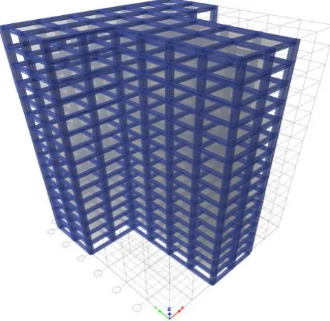
Fig 2 3D View of T shaped building with grid slab
[image:2.595.310.563.331.485.2]Fig.3 Plan of T shaped building with flat slab
Fig 4 3D View of T shaped building with flat slab
Fig.5 Plan of L shaped building with grid slab
[image:2.595.44.285.482.716.2] [image:2.595.317.550.544.698.2]© 2017, IRJET | Impact Factor value: 5.181 | ISO 9001:2008 Certified Journal
| Page 666
Fig.7 Plan of L shaped building with flat slabFig.8 3D view of L shaped building with flat slab
4. ASSIGNING LOADS Dead Load
Slab Weight calculation:
Thickness of slab = 0.125m
Density of concrete = 25kN/m3
Self-weight of slab = Density of concrete x Thickness
of
= 25x0.125 = 3.125kN/m2 Floor Finish load calculation:
Floor load = Density of floor material x thickness of floor
= 20 x 0.05 = 1 kN/m2
Live Load
Floor load:
Live Load Intensity specified (Commercial building) =
4kN/m2(IS: 875 (Part 2) – 1987)
Live Load at roof level = 1.5 kN/m2 Load Combinations
Following are the load combinations provided for each models for the analysis purposes.
1.
DL2.
DL+LL3.
1.5(DL+LL)4.
1.2(DL+LL+ELX)5.
1.2(DL+LL+ELY)6.
1.2(DL+LL-ELX)7.
1.2(DL+LL-ELY)8.
1.5(DL+ELX)9.
1.5(DL+ELY)10.
1.5(DL-ELX)11.
1.5(DL-ELY)12.
0.9DL+1.5ELX13.
0.9DL+1.5ELY14.
0.9DL-1.5ELX15.
0.9DL-1.5ELY5. ANALYSIS
After assigning the loads to the structure, Response spectrum analysis is carried out to evaluate the shear force bending moment, axial force and dynamic results in the form of storey shear.
Response spectrum analysis
© 2017, IRJET | Impact Factor value: 5.181 | ISO 9001:2008 Certified Journal
| Page 667
Fig.9 Response Spectrum CurveAnalysis results
From the output of ETABS, various results are obtained. And these results are tabulated and evaluated by preparing various graphs.
Storey Shear
[image:4.595.305.564.127.348.2]The base shear is a estimate of the maximum expected lateral force that will occur due to the seismic ground motion at the base of a structure. Calculations of base shear depend on soil conditions at the site, proximity to potential sources of seismic activity
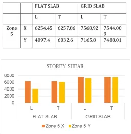
Table 4 Maximum Storey Shear for plan irregular Buildings with flat slab and grid slab in zone V
FLAT SLAB GRID SLAB
L T L T
Zone
5 X 6254.45 6257.86 7568.92 7544.009
Y 4097.4 6032.6 7165.8 7488.01
Fig 10 Maximum Storey shear in zone V for different types of structures with flat slab and grid slab
Table 5 Maximum storey shear in zone III for different types of buildings with flat slab and grid slab
FLAT SLAB GRID SLAB
L T L T
Zone
3 X Y 2779.75 2781.271 3363.96 3352.89 1821.08 2681.16 3184.82 3284.23
Fig 11 Maximum Storey Shear in zone III for different types of structures with flat slab and grid slab
6. CONCLUSIONS
In this the seismic analysis is carried out to study the comparison between flat slab with drop structures and grid slab structures under different conditions for different parameters and from the above results it can be concluded that
1. Grid slab structures have maximum base shear in comparison with flat slab with drop in both zones
ACKNOWLEDGEMENT
The authors can acknowledge any person/authorities in this section. This is not mandatory.
REFERENCES
[1] Apostolska et al. (2008),“Use of flat slabs in multi-storey commercial building situated in high seismic zone”, Vol.03, No. 08, IJRET: International Journal of Research in Engineering and Technology
[2] Bothara and Varghese (2012),”Dynamic analysis of multi-storey RCC building frame With flat slab and grid slab”, Al Int. Journal of Engineering Research and Applications, Vol. 4, No. 2, Version 1, pp. 416-420.
[image:4.595.35.292.448.711.2]© 2017, IRJET | Impact Factor value: 5.181 | ISO 9001:2008 Certified Journal
| Page 668
rise building”,Volume No.05, International Journal of Engineering Research.
[4] Navyashree K and Sahana T S (2014), “Parametric study of flat slab building with and without shear wall to seismic performance”, Vol.04, No. 04, IJRET: International Journal of Research in Engineering and Technology.