© 2017, IRJET | Impact Factor value: 5.181 | ISO 9001:2008 Certified Journal
| Page 1572
Analytical study of diagrid structural system for rectangular and
rectangular-chamfered multistory building
Deeksha T Ballur
1, M Manjunath
21
Post Graduate student in Structural Engineering, Dept of Civil Engineering, KLE Dr. MSS CET Belagavi,
Karnataka, India
2
Associate Professor, Dept of Civil Engineering, KLE Dr. MSS CET, Belagavi, Karnataka, India
---***---Abstract -
In modern age, construction of high-risebuildings is rapidly increasing throughout the world. Due to the decrease of available free land and due to the wide spread urban area, the architects and the engineers have started developing the cities vertically. Recently, the diagrid structural system has been widely used for tall buildings due to structural efficiency and aesthetic potential provided by the triangulation of the systems. Compared to the conventional frame buildings having exterior vertical columns, diagrid buildings resist the lateral loads more effectively due to the presence of the inclined columns. . In the present study, a 36-storey steel building is taken for the comparison. Types of buildings considered for comparison are as follows: diagrid frame building with rectangular plan and diagrid frame building with rectangular plan along with chamfered edges. All these buildings are modeled and analyzed for earthquake loads and wind loads respectively. The design of structural members is done as per IS 800:2007. Comparison is done in terms of storey displacement, storey drift, base shear, time period, storey stiffness and structural weight. In this study, it is found that the storey displacements and the inter storey drifts reduce simultaneously as the shape of the building takes a curved form avoiding the edges.
Key Words: Earthquake, Wind, Diagrid structural form, Chamfered edges, ETABS.
1.
INTRODUCTION
The rapid growth of population and scarcity of land have considerably influenced the residential development of the city. The high expenses of land and desire to preserve important agricultural production have led to the upward growth of buildings. As the height of building increases, lateral load resisting becomes a challenge to the structural engineers. With the increase in the height of the building the lateral loads acting on the structure increases and becomes more important than the structural system that resists gravity loads. The lateral load resisting systems that are used in practice include rigid frames, shear wall, wall frame, braced tube system, outrigger system and tubular system. Appropriate lateral resisting system for tall buildings depend on number of factors which include: locally available materials and construction technology, building program and function, architectural form and
very importantly, the type and magnitude of lateral loads. Even in the regions of high seismicity, as the building gets taller, the system selection and material quantities are governed by the wind loads [1].
“A Diagrid System is defined as the structural system which creates triangulated structural geometry at the exterior -surface of the building with the help of diagonally supporting beams” [2]. The term “Diagrid” arises from the combination of words “diagonal” and “grid” and refers to a structural system that gains its structural integrity through use of triangulation. Diagrid structural systems can be planar, crystalline or take a multiple curvature but usually they use crystalline forms to increase their stiffness. Along with carrying gravity loads and lateral loads, the perimeter grid made up of a series of triangulated truss system. The number of stories covered under a single diagrid is called as a module [3].
Prime requirement of a high rise building is the safety and minimum damage level. To meet these requirements, the structure should have adequate lateral strength and sufficient ductility. The objectives of the present study can be outlined as follows:
1. To study the performance of the diagrid structural form for a rectangular planed building and rectangular planed building with chamfered edges under lateral forces, in terms of displacements, inter storey drifts, base shears, time periods, storey stiffness and structural steel weight.
2. To evaluate the effect of chamfering the building corners of a tall building having a diagrid structural form, under wind forces.
3. To compare the efficiency of diagrid structural form for a tall building with different floor plan configuration.
2.
LITERATURE REVIEW
© 2017, IRJET | Impact Factor value: 5.181 | ISO 9001:2008 Certified Journal
| Page 1573
buildings. Many works have been carried out on diagrid structural system and its comparison with the conventional framed building having a symmetrical plan dimensions. From the study, we got to know that a diagrid building with 36 storey height, 4-storey diagrid model with a diagonal inclination of 67.38˚ gives the optimal results. From the literature review it is evident that the study on diagrid structural system for curved forms of buildings is limited.
3.
MODELING AND ANALYSIS
With an objective of evaluating and comparing the performance of diagrid structural form, an analytical study is taken up on tall building structures. The study is based on a 36-story commercial building analyzed for wind and seismic forces as per the Indian standard codes. Along with dead and live loads, the structure is analyzed for earthquake loads and wind loads and the comparison of results is done in terms of maximum lateral displacements, maximum storey drifts, base shear, time period, storey stiffness and structural steel weight.
3.1 MATERIAL PROPERTIES:
All the structural elements are modeled as linearly elastic elements. All the buildings are modeled as steel structures assigning steel properties to the beams, columns and braces. Deck is modeled as a concrete filled membrane element. Design is done for all the models as per IS 800: 2007 for both gravity loads and lateral loads.
Steel properties
Grade of steel: Fe 250
Modulus of elasticity: 200Gpa
Concrete properties
Grade of concrete: M30
Density of Reinforced concrete: 25kN/m3
Poisson’s ratio: 0.2
Coefficient of thermal expansion: 5.5×10⁶/˚C
3.2
STRUCTURAL FORMS:
To study the effect of chamfering the building edges, the study is carried out on two basic structural models for both earthquake loads and wind loads respectively. A 36-storey steel framed building is considered. Typical floor height for all the stories is 3.6m. The inclination of the diagrid members is kept uniform throughout the structure. In total, 2 models are done in this study that is a diagrid framed building with rectangular plan and diagrid framed building with rectangular plan along with chamfered edges. All these above buildings are dimensioned such that they have the same plan area of 1296m2.
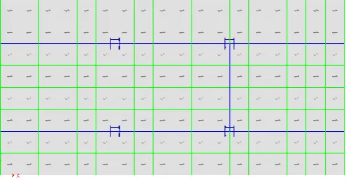
3.2.1 MODEL 1: DIAGRID FRAMED BUILDING - RECTANGULAR PLAN (M1: DG-F-Rect)
The diagrid framed building is a steel structure comprising of vertical columns only at the interior core frame of the building mainly to resist the gravity loads. The peripheral framing consists of diagrid members which are modeled as a 3D truss elements, pin connected at each floor. Diagrid members are placed at a spacing of 6m and are provided with the hinge support at the base. The diagrid considered in this study are 4-storey diagrid module with the diagonal inclination of 67.38˚. Along with the beams that develop the connectivity with vertical columns, there are ring beams that run along the periphery of the building which are necessary to hold the diagrid members in position.
Plan dimensions: 24m×54m
Deck sections: 150mm thick concrete filled steel deck (M30)
Column sections:1.5m×1.5m built-up section (at the internal frame)
Beam sections: 300mm×600mm I-section with 50mm thick flange and web, with 220mm wide and 50mm thick cover plates on the either side of the section. (Primary beams connecting the internal columns) and 250mm×600mm I-section with 50mm flange and web thickness (Secondary beams connecting internal columns to the external ones)
[image:2.595.312.560.520.649.2] Diagrids: 4-storey module diagrid system with diagonal inclination of 67.38˚. Steel pipe of 600mm diameter and 50mm thick (1-19storey). Steel pipe of 450mm diameter and 25mm thick (20-36storey).
Figure 3.1: Plan dimensions of diagrid framed building with rectangular plan (DG-F-Rect)
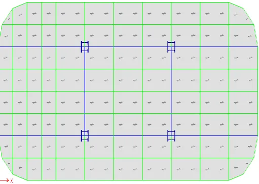
3.2.2 MODEL 2: DIAGRID FRAMED BUILDING -
RECTANGULAR PLAN WITH CHAMFERED EDGES (M2: DG-F-Rect-C)
© 2017, IRJET | Impact Factor value: 5.181 | ISO 9001:2008 Certified Journal
| Page 1574
[image:3.595.42.298.134.316.2]providing a chamfered surface along all the 4 corners of the building with chamfered radius of 6m.
Figure 3.2: Plan dimensions of diagrid framed building - rectangular plan with chamfered edges (DG-F-Rect-C)
3.3 LOADS:
3.3.1 DEAD LOAD
The self-weight of the structure is taken by the software automatically and the floor finish on each floor is taken as 1kN/m2.
3.3.2 LIVE LOAD
As per IS 875 (Part 2) 1987 [9], live load on floors for a commercial building is taken to be 5kN/m2.
3.3.3 EARTHQUAKE LOADS
All the structures are analyzed for horizontal seismic forces along the x and y directions. The seismic forces are in accordance to IS 1893 (part 1):2002 [8], assuming the building as located in zone III. Analysis was done assuming seismic zone III, medium soil type, importance factor 1, response reduction factor of 5.0 and SMRF structural system.
3.3.4 WIND LOADS
The analysis for the wind loads is done as per the IS code 875 (part 3) 1987 [10]. As the height to minimum lateral dimension ratio of the building exceeds 5, gust factor method is to be used for the calculation of the wind loads. Analysis was done assuming wind zone V, life of structure as 100 years, terrain category 3 and a plain topography. Along wind load on a structure on a strip area (Ae) at any height (z) is given by, Fz=Cf×Ae×Pz×G
Primary calculations:
Probability factor [k1]: 1.08
Height factor [k2]: varies with floor height, as in table 3.1 Topography factor [k3]: 1
Effective frontal area [Ae]:
Spacing of frame ×Floor height
Intermediate floor node: 21.6 m2
Roof node: 10.8 m2 Design wind speed [Vz] = k1×k2×k3×Vb Design wind pressure [Pz] = 0.6× (Vz) 2
Gust Factor [G]:
Is given by: G= 1+gtr √ [B (1+Φ) 2+SE/β] The Gust factor is worked out as, G = 1.90
Force Coefficient (Cf):
[image:3.595.341.528.404.462.2]It is calculated for rectangular building from Figure 4A of IS 875 (part 3) 1987 and for building with chamfered edges from Table 23 of IS 875 (part 3) 1987. It is shown in table 3.1
Table 3.1: Force Coefficient values (Cf):
Direction DG-F-Rect DG-F-Rect-C X direction 1.200 0.508 Y direction 1.200 1.013
The wind loads are calculated and applied at each node respectively for all the buildings and then the analysis of the model is carried out.
4. STRUCTURAL BEHAVIOUR: EVALUATION AND PERFORMANCE
The objective of studying the behavior of diagrid structural form and the effect of chamfering is done through a comparative study of various parameters which reflect the structural response of the various models under different loads. The comparison is done in terms of storey displacements; inter storey drifts, base shears, time periods, storey stiffness and structural steel weight.
4.1 STOREY DISPLACEMENT DUE TO EARTHQUAKE LOADS:
© 2017, IRJET | Impact Factor value: 5.181 | ISO 9001:2008 Certified Journal
| Page 1575
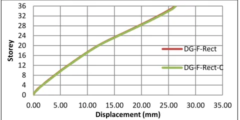
Figure 4.1 Storey Displacements due to earthquake loads [image:4.595.41.283.251.390.2]along X direction by equivalent static method
[image:4.595.314.555.303.441.2]Figure 4.2 Storey Displacements due to earthquake loads along X direction by response spectrum method
Figure 4.3 Storey Displacements due to earthquake loads along Y direction by equivalent static method
Figure 4.4 Storey Displacements due to earthquake loads along Y direction by response spectrum method
Observations: The storey displacements due to earthquake loads given by equivalent static method are higher than response spectrum method. For all the two structural forms considered in the study, the maximum lateral displacements (due to earthquake loads) along y direction are higher than along x direction. The storey displacements of all the two diagrid framed buildings (DG-F-Rect and DG-(DG-F-Rect-C) subjected to earthquake loads are almost same in magnitude.
4.2 STOREY DISPLACEMENTS AND INTER STOREY DRIFTS DUE TO WIND LOADS
The comparison of the two structural forms are presented below graphically for X and Y directions respectively.
Figure 4.5 Storey displacements due to wind loads along X direction
Figure 4.6 Storeydisplacements due to wind load along Y direction
0 4 8 12 16 20 24 28 32 36
0.00 5.00 10.00 15.00 20.00 25.00 30.00
St
ore
y
Displacement (mm)
DG-F-Rect DG-F-Rect-C
0 4 8 12 16 20 24 28 32 36
0.00 5.00 10.00 15.00 20.00
St
ore
y
Displacement (mm)
DG-F-Rect DG-F-Rect-C
0 4 8 12 16 20 24 28 32 36
0.00 10.00 20.00 30.00 40.00 50.00 60.00
St
ore
y
Displacement (mm)
DG-F-Rect DG-F-Rect-C
0 4 8 12 16 20 24 28 32 36
0.00 5.00 10.00 15.00 20.00 25.00 30.00 35.00
St
ore
y
Displacement (mm)
DG-F-Rect
DG-F-Rect-C
0 4 8 12 16 20 24 28 32 36
0.00 5.00 10.00 15.00 20.00
St
ore
y
Displacement (mm)
DG-F-Rect DG-F-Rect-C
0 4 8 12 16 20 24 28 32 36
0.00 20.00 40.00 60.00 80.00 100.00 120.00
St
ore
y
Displacement (mm)
[image:4.595.42.283.431.568.2] [image:4.595.312.555.482.621.2] [image:4.595.41.282.614.734.2]© 2017, IRJET | Impact Factor value: 5.181 | ISO 9001:2008 Certified Journal
| Page 1576
Figure 4.7 Interstorey drifts due to wind loads along X [image:5.595.40.282.86.228.2]direction
Figure 4.8 Interstorey drifts due to wind loads along Y direction.
Observations: For the two structural forms considered in the study, the maximum lateral displacements and maximum inter storey drifts (due to wind loads) along y direction are higher than along x direction.The maximum storey displacements and the maximum inter storey drifts in descending order for the two diagrid structural forms studied are; ‘DG-F-Rect’ and ‘DG-F-Rect-C’ respectively.
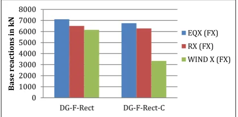
4.3 BASE REACTIONS
The reactions at the base of the structure due to dead load, live load and wind load along x direction and y direction for the structural forms considered in the study are as below.
Figure 4.9 Base reactions due to earthquake loads and wind loads along X direction
Figure 4.10 Base reactions due to earthquake loads and wind loads along Y direction
Observations: The base reactions due to dead load and live load appear to be same for all the buildings. In x direction, the base reaction due to earthquake loads is greater than that due to wind loads where as in y direction, the base reaction due to wind loads is higher than that due to earthquake loads.
4.4 TIME PERIOD
Time periods of the buildings considered for the study for each mode is as shown below.
Figure 4.11 Time periods of structural forms
Observations: The fundamental time period of ‘DG-F-Rect’ is more as compared to that of ‘DG-F-Rect-C’.
4.5 STOREY STIFFNESS
The comparison of the two structural forms with respect to maximum storey stiffness (1st storey) along x direction and y direction are presented below graphically.
0 4 8 12 16 20 24 28 32 36
0.00 0.05 0.10 0.15 0.20
St
ore
y
Storey Drifts×10-3
DG-F-Rect DG-F-Rect-C
0 4 8 12 16 20 24 28 32 36
0.00 0.50 1.00 1.50
St
ore
y
Storey Drifts×10-3
DG-F-Rect DG-F-Rect-C
0 1000 2000 3000 4000 5000 6000 7000 8000
DG-F-Rect DG-F-Rect-C
B
as
e
re
ac
tion
s
in
k
N
EQX (FX) RX (FX) WIND X (FX)
0 5000 10000 15000
DG-F-Rect DG-F-Rect-C
B
as
e
re
ac
tion
s
in
k
N
EQY (FY) RY (FY) WIND Y (FY)
3.04 3.06 3.08 3.10 3.12 3.14 3.16
DG-F-Rect DG-F-Rect-C
Fun
dam
en
tal
tim
e
pe
[image:5.595.41.283.263.393.2] [image:5.595.317.547.414.566.2] [image:5.595.41.282.609.727.2]© 2017, IRJET | Impact Factor value: 5.181 | ISO 9001:2008 Certified Journal
| Page 1577
Figure 4.12Storey stiffness of structural formsObservations: The storey stiffness along x direction is of higher magnitude as compared to that along y direction for all the buildings. The storey stiffness of ‘DG-F-Rect-C’ is more than ‘DG-F-Rect’.
4.6 STRUCTURAL WEIGHT
The structural steel weight of all the 2 buildings considered in the study is as given below.
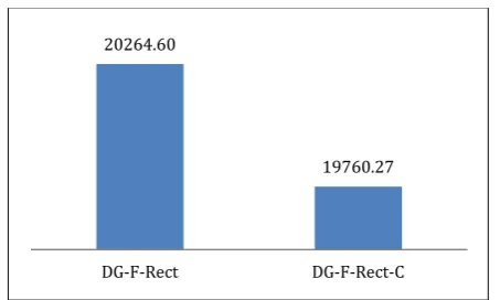
Figure 4.13 Structural steel weights (Tones) of structural forms
Observations: The structural steel weight of ‘DG-F-Rect’’ structure is higher than the corresponding weight of ‘DG-F-Rect-C’.
Concluding remarks:
The diagrid framed building with chamfered edges have less storey displacements and less inter storey drifts making the structure stiffer as compared to the diagrid framed building with rectangular plan.
5.
DISCUSSIONS AND CONCLUSION
The two plan configuration of diagrid buildings considered in the study are diagrid framed building with rectangular plan (DG-F-Rect) and diagrid framed building with rectangular plan along with chamfered edges (
DG-F-Rect-C). Modelling and analysis is done in ETABS 2015. Based on the results and observations, following conclusions are made:
Storey Displacement due to earthquake loads:
The maximum displacements of the two buildings considered in the study lie within the permissible limit i.e., h/500
The storey displacements along both x direction and y direction given by equivalent static method are about 30% higher than that by response spectrum method. Since the equivalent static method is based on assumed time period, the estimated displacements are higher.
The lateral displacements along y direction are higher than along x direction for all the buildings considered in the study. The reason for this behaviour is that the stiffness of the buildings in y direction is lesser than that in x direction.
The storey displacements of the two diagrid framed buildings along X direction obtained by equivalent static method are almost same in magnitude; DG-F-Rect (24.590mm) and DG-F-DG-F-Rect-C (24.950mm). Similarly, the storey displacements of the two diagrid framed buildings along Y direction obtained by equivalent static method are almost same in magnitude; DG-F-Rect (43.668mm) and DG-F-Rect-C (43.310mm).Similar results are obtained by response spectrum method of analysis.
This is because in earthquake analysis the building is subjected to random motions of ground at its base and thus the displacements caused is dependent on the mass and structural form of the building but independent of the building shape.
Thus, it can be said that the storey displacement does not depend on the shape of the building (chamfering the edges) as both the diagrid framed buildings have nearly the same maximum storey displacements.
Storey Displacements and inter storey drifts due to wind loads:
The maximum displacements and the maximum inter storey drifts of all buildings considered in the study lie within the permissible limit i.e., h/500 and 0.004h respectively.
As the stiffness of the buildings in y direction is lesser than x direction, the maximum lateral displacements and maximum inter storey drifts due to wind loads along y direction are higher than that due to wind loads along x direction for all the buildings considered in the study.
In x direction and y direction, the maximum storey displacement of ‘DG-F-Rect’ (14.497mm, 102.259mm) is greater than ‘DG-F-Rect-C’ (8.413mm, 99.225mm) respectively. In x direction and y direction, the 0.00
5.00 10.00 15.00 20.00 25.00 30.00 35.00 40.00 45.00 50.00
DG-F-Rect DG-F-Rect-C
St
ore
y
St
iff
n
es
s
×
10
6 (
k
N
/m
)
X direction Y direction
20264.60
19760.27
[image:6.595.49.276.390.526.2]© 2017, IRJET | Impact Factor value: 5.181 | ISO 9001:2008 Certified Journal
| Page 1578
maximum inter storey drift of ‘DG-F-Rect’ (0.162×10⁻³, 1.130×10⁻³) is greater than ‘DG-F-Rect-C’ (0.093×10⁻³, 1.107×10⁻³) respectively. Because here the displacements are caused due to wind load which is enforced on the exposed surface area of the building and thus as the shape of the building takes a curved surface the displacement gets reduced.
Thus, as the building edges are avoided and as the building shape leads to a curved surface, the maximum storey displacement and maximum inter storey drifts gets reduced simultaneously.
Base shear:
For all the buildings considered in the study, the base shear due to dead load and live load are nearly the same as the plan area the respective loads applied to each of the buildings are similar.
As the base shear of the building depends on the total lateral force on the structure, as the structure takes a curved form the lateral wind load on the structure reduces and thus the value of base shear descends as the building takes a curved form on the periphery.
Along x direction the base shears of all the buildings due to earthquake loads are greater than base shears due to wind loads, where as in y direction the base shears due to wind loads are higher than the base shears due to earthquake loads. Hence it can be said that the wind loads govern the design of the building.
Time Period:
The time period of diagrid frame building with rectangular plan (3.15) is greater than diagrid frame building with rectangular plan having chamfered edges (3.078).
As the time period decreases, the stiffness of the structure increases. Hence it is concluded that the structure with the chamfered edges is more stable as compared to the other building considered in the study.
Storey stiffness:
Along both the directions, the stiffness value of the diagrid framed building with chamfered edges (DG-F-Rect-C) is greater than stiffness of rectangular planed diagrid frame building (DG-F-Rect). As the geometry of the building becomes continuous avoiding the edges the stiffness goes on increasing.
Structural weight:
The structural weight of the 2 diagrid buildings is nearly the same. Diagrid structural form has a material saving strategy as the structural steel consumption of a diagrid frame building is less than that of a conventional rigid frame building.
The storey displacements and the inter storey drifts of the diagrid building with chamfered edges are found to be less than that of the diagrid building with rectangular plan due to continuous peripheral surface. And hence the stiffness of the building also increases as the building takes a curved form.
REFERENCES
1. Jani, K., Patel, P. V., (2013). “Analysis and Design of Diagrid Structural System for High Rise Steel”, Chemical, Civil and Mechanical Engineering Tracks of 3rd Nirma University International Conference on Engineering, Procedia Engineering 51 pp. 92 – 100, ELSEVIER publication 2013 2. Deshpande, R. D., Patil, S. M., Ratan, S., “Analysis
And Comparison Of Diagrid and Conventional Structural System”, International research journal of Engineering and Technology.,Volume:02, Issue No:03,June 2015
3. Saket, Yadav., Vivek, Garag., “Advantage of steel diagrid building over conventional building”, International Journal of Civil and Structural Engineering research, Vol. 03. Issue 1, ISSN 2348-7607, April 2015-September 2015
4. Femy, Mariya. Thomas., Binu, M. Issae., Jessymol, George., “Performance Evaluation of Tall Buildings with Steel Diagrid System”, 2nd International Conference on Science, Technology and Management. ,University of Delhi, Conference center, New Delhi (India) September 2015
5. Rupa, Garai., Mark, Sarkisian., “ Three dimensional Exterior Bracing Systems for Tall Buildings” CTBUH 2015 New York Conference
6. Pallavi, Bhale., P, J. Salunke., “Analytical Study and design of diagrid building and comparison with conventional frame building”, International Journal of advanced Technology in engineering and science, Vol. No. 4,Issue no.01,January 2016 7. IS 800:2007, “General Construction in Steel-Code
of Practice, Bureau of Indian Standard, New Delhi” 8. IS 1893 (part 1):2002, “Criterion for Earthquake Resistant Design of Structures, Bureau of Indian Standard, New Delhi”
9. IS 875 (part 2):1987, “Code of Practice for Design Loads (Other than Earthquake) for Buildings and Structure, Bureau of Indian Standard, New Delhi” 10. IS 875 (part 3):1987, “Code of Practice for Design