Comparative Parametric Study of Seismic Behaviour of RC Framed
Building With & Without Floating Column In Different Configuration
Shreyans Kumar Jain
1, Prof. Nidhi Gupta
21
PG Student in Structural Engineering, Department of Civil Engineering, RKDF-IST, Bhopal (M.P.), India
2
Head of the Department of Civil Engineering, RKDF-IST, Bhopal (M.P.), India
---***---Abstract - With the increasing demand for residential
and commercial space, people preferring vertical system i.e. high rise buildings. And for large uninterrupted space required for the movement of people or vehicles concept of floating columns is often used. The load transfer takes place from horizontal members to vertical members and finally transferred to foundation level, hence, there should be a clear load path available for the load to reach the foundation level. But Floating columns are discontinued at its lower level and rest on a horizontal member, usually beams. This discontinuity of columns at any floor changes the load path and transfers load of the floating column through horizontal beams supporting it. This altered path causes large vertical earthquake forces due to overturning effect. Therefore, where floating columns are provided, special care should be given to the transfer girders and column below the floating column. In the present work, variation in seismic behaviour due to presence of floating columns is studied. Also the effect of configuration of floating column is noted. For the purpose three different models of G+20 RC framed building are prepared and analysed using STAAD.Pro V8i software by Equivalent Static Method and a comparative study based on parameters such as axial force, shear, moment, base shear and displacement has been done. The study reveals that floating columns should be avoided in severe seismic zones and if not avoidable then corner columns should not be floated as the magnitude of design parameters are more severe in such configuration.Key Words: Floating Column, STAAD.Pro V8i, Equivalent Static Method, Average Storey Displacement, Storey Drift, Base Shear.
1.
INTRODUCTION
Floating Column is a column which does not reaches to foundation level and hence also does not transfer the load carried by it to the ground. It rests on a beam which acts as a transfer girder and transfers the loads to other column(s) on which the beam rests. The floating column in this way discontinued at that beam level. This is done due to may be architectural design or site situation. A primary objective of doing this is to create an interrupted space below the columns which can be
this feature is very common in high rise buildings. Most of the time, architect demands for the aesthetic view of the building, in such cases also many of the columns are terminated at certain floors and floating columns are introduced and hence such buildings are planned and constructed with architectural complexities. This discontinuation of columns introduces vertical irregularities in the structure and elongates the load transfer path which may prove to be detrimental, especially, in seismic conditions, if not taken care properly. So when irregular features such as above are included in buildings, a considerably higher level of engineering effort is required in the structural planning and design. Therefore, where provision of floating column is necessary, special care should be given to the transfer girders and columns below the transfer girders. These beams and columns should have sufficient strength to receive the load from floating column and convey it to the lower level.
2.
OBJECTIVE OF THE PRESENT STUDY
The main objective of the present work is to study the effect of presence of floating columns in different configurations on seismic response of a G+20 RC Framed building under the provisions of different IS codes and with the help of STAAD.Pro software. Parameters to be compared are Column & Beam Forces, Average Displacement and Storey Drift.
3.
METHODOLOGY
To achieve the objective, three Models of a G+20 RC framed building which differs in configuration of floating columns, introduced above ground floor, are prepared & analysed using STAAD.Pro V8i and results are compared. All the models are assumed to be situated in Seismic Zone IV.
3.1
Modelling
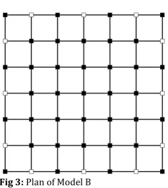
normal model (Model 0) is prepared with no floating column which provides the basic data to compare the models with floating columns (Fig.1). In other two models 12 columns in outer periphery are removed at ground floor level i.e. columns above GF are made floating columns. A model with 12 floating columns in alternate including Corner columns named here as Model A, is prepared (Fig.2). And the third model is one which also has 12 floating columns in alternate but excluding corners named Model B (Fig.3). (Empty column represents Floating column and filled column represents normal columns.)
Fig 1: Plan of Model 0
Fig 2: Plan of Model A
Fig 3: Plan of Model B
3.2
Method of Analysis
The IS Code 1893 (Part 1):2002 recommends two methods for seismic analysis viz. Seismic coefficient method popularly known as Equivalent Static method, and Dynamic method. In the present work former method is adopted. Equivalent Static Analysis approach defines a sequence of lateral forces acting on a building to represent the forces generated due to earthquake ground motion, typically defined by a seismic design response spectrum. The basic assumption is that the building responds in its fundamental mode. Given the natural frequency of the building, the response is examined from a design response spectrum. The lateral equivalent forces are calculated and then distributed along the height of the building using empirical equations as per the clause 6.4 and 7.5 of IS Code 1893 (Part 1): 2002.
(i)Design lateral force or seismic base shear:
The total design seismic base shear (VB) shall be determined along any principal direction by the following expression:
VB = Ah W Where,
Ah = Design horizontal seismic coefficient by using
fundamental natural period (Ta) = =
W = Seismic weight of the whole building as per clause 7.4.2
Z = Zone factor. I = Importance factor
R = Response reduction factor
Sa/g = Average response acceleration coefficient for rock and soil sites.
Ta = Approximate fundamental natural period of vibration for moment resisting frame building
in seconds =
[image:2.595.35.207.255.624.2]d = Base dimension of the building, in m, along the considered principal direction of the lateral force.
(ii)Distribution of Base Shear and Design Force:
The computed design base shear (VB) shall be distributed along the building height by following expression:
Qi = VB∑
Where,
Qi = Design lateral force at floor i. Wi = Seismic weight of floor i.
hi = Height of floor i measured from base.
n = Number of storey in the building (number of levels at which the masses are located)
STAAD.Pro V8i software calculates and applies the static seismic forces to analyse the structure in accordance with the procedures as recommended by the relevant IS Codes.
3.3
Design Loads
Various loads and load combinations in accordance with IS Codes 875 (Part I):1987, 875 (Part II): 1987, IS 456: 2000 and IS 1893 (Part 1): 2002 are taken into consideration, acting on the building models.
4.
RESULTS AND DISCUSSION
Results for all the models are obtained, summarised by taking maximum absolute values of each parameter and compared as follows:
Table - 1: Results (Maximum Absolute Values)
Models Model 0 Model A Model B
CO LU M N F O R
CES Axial Force Location of Col. (Fx) kN 3969 BGF 5955 GF 5768 GF Shear-Y (Fy) kN 94.632 206.246 142.334
Location of Col. 6th Flr. 1st Flr. 1st Flr.
Moment-Z (Mz) kNm 148.516 382.340 253.216
Location of Col. BGF 1st Flr. 1st Flr.
BE A M FO R CES
Shear-Y (Fy) kN 137.250 395.080 381.991
Location of Beam 7th Flr. 1st Flr. 1st Flr.
Moment-Z (Mz) kNm 169.749 592.049 550.702
Location of Beam 7th Flr. 1st Flr. 1st Flr.
Base Shear 2328.67 2321.21 2321.21 Avg. Disp. Of Top Storey (mm) 35.329 41.598 39.911
[image:3.595.314.547.347.541.2]Storey Drift (mm) At GF 1.487 1.936 1.899 At 8th Flr. 1.908 2.198 2.116
Table - 2: Comparison of Results (Model A v/s Model 0)
Models Model 0 Model A Difference (%) CO LU M N F O R
CES Axial Force Location of Col. (Fx) kN 3968.662 BGF 5954.885 GF 1986.223 50.0% Shear-Y (Fy) kN 94.632 206.246 111.614 Location of Col. 6th Flr. 1st Flr. 117.9% Moment-Z (Mz) kNm 148.516 382.340 233.824
Location of Col. BGF 1st Flr. 157.4%
BE A M FO R CES
Shear-Y (Fy) kN 137.250 395.080 257.830 Location of Beam 7th Flr. 1st Flr. 187.9% Moment-Z (Mz) kNm 169.749 592.049 422.300 Location of Beam 7th Flr. 1st Flr. 248.8%
Base Shear 2328.67 2321.21 -7.461 -0.3%
Avg. Disp. of Top Storey (mm) 35.329 41.598 6.269 17.7%
Storey Drift (mm)
At GF 1.487 1.936 0.449 30.2%
At 8th Flr. 1.908 2.198 0.290 15.2%
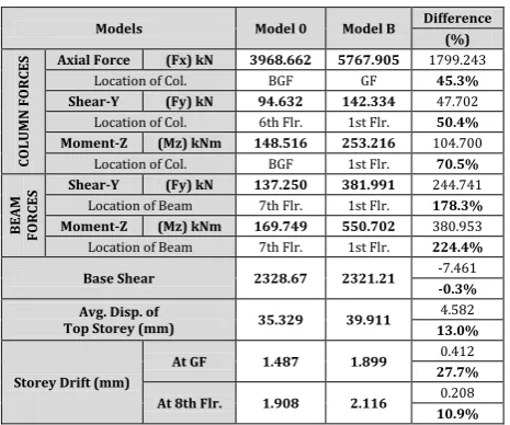
Table - 3: Comparison of Results (Model B v/s Model 0)
Models Model 0 Model B Difference (%) CO LU M N F O R
CES Axial Force Location of Col. (Fx) kN 3968.662 BGF 5767.905 GF 1799.243 45.3% Shear-Y (Fy) kN 94.632 142.334 47.702
Location of Col. 6th Flr. 1st Flr. 50.4% Moment-Z (Mz) kNm 148.516 253.216 104.700
Location of Col. BGF 1st Flr. 70.5%
BE A M FO R CES
Shear-Y (Fy) kN 137.250 381.991 244.741 Location of Beam 7th Flr. 1st Flr. 178.3% Moment-Z (Mz) kNm 169.749 550.702 380.953 Location of Beam 7th Flr. 1st Flr. 224.4%
Base Shear 2328.67 2321.21 -7.461 -0.3% Avg. Disp. of
Top Storey (mm) 35.329 39.911
4.582
13.0%
Storey Drift (mm)
At GF 1.487 1.899 0.412 27.7%
At 8th Flr. 1.908 2.116 0.208 10.9%
Table - 4: Comparison of Results (Model B v/s Model A)
Models Model A Model B Difference (%) CO LU M N F O R
CES Axial Force Location of Col. (Fx) kN 5954.885 GF 5767.905 GF -186.980 -3.1% Shear-Y (Fy) kN 206.246 142.334 -63.912
Location of Col. 1st Flr. 1st Flr. -31.0% Moment-Z (Mz) kNm 382.340 253.216 -129.124
Location of Col. 1st Flr. 1st Flr. -33.8%
BE A M FO R CES
Shear-Y (Fy) kN 395.080 381.991 -13.089 Location of Beam 1st Flr. 1st Flr. -3.3% Moment-Z (Mz) kNm 592.049 550.702 -41.347 Location of Beam 1st Flr. 1st Flr. -7.0%
Base Shear 2321.21 2321.21 0.000 0.0% Avg. Disp. of
Top Storey (mm) 41.598 39.91
-1.687
-4.1%
Storey Drift (mm)
At GF 1.936 1.899 -0.037 -1.9%
Chart-1: Column Axial Force (Fx) kN
Chart-2: Column Shear Force (Fy) kN
Chart-3: Column Moment (Mz) kNm
Chart-4: Beam Shear Force (Fy) kN
Chart-5: Beam Moment (Mz) kNm
Chart-6: Base Shear (Vb) kN
3969
5955 5768
0 1000 2000 3000 4000 5000 6000 7000
Model 0 Model A Model B
Column Axial Force (Fx) kN
94.632
206.246
142.334
0.000 50.000 100.000 150.000 200.000 250.000
Model 0 Model A Model B
Column Shear-Y (Fy) kN
148.516
382.340
253.216
0.000 50.000 100.000 150.000 200.000 250.000 300.000 350.000 400.000 450.000
Model 0 Model A Model B
Column Moment-Z (Mz) kNm
137.250
395.080 381.991
0.000 50.000 100.000 150.000 200.000 250.000 300.000 350.000 400.000 450.000
Model 0 Model A Model B
Beam Shear-Y (Fy) kN
169.749
592.049
550.702
0.000 100.000 200.000 300.000 400.000 500.000 600.000 700.000
Model 0 Model A Model B
Beam Moment-Z (Mz) kNm
2329
2321 2321
2316 2318 2320 2322 2324 2326 2328 2330
Model 0 Model A Model B
Chart-7: Average Displacement (mm)
It can be seen from above that when the floating columns are introduced the values various parameters increase. In Model A the magnitude of maximum Axial Force, Shear Force and Moment in Column is increased by 50%, 118% and 157% respectively, as compared to Model 0 while these increments are limited to 45%, 50% and 71% respectively in case of Model B. Similarly, the Beam forces viz. Shear Force and Moment are hiked to 188% and 249% for Model A whereas 178% and 224% for Model B respectively. Value of Base Shear is reduced for both the models as Seismic weight of building is reduced due to removal of columns at ground floor level. Average Displacement of top storey is enhanced by 18% and 13% for Model A & B respectively. The magnitude of Storey Drift at GF level & at 8th floor level are increased respectively by 30% & 15% for Model A and 28% & 11% for Model B.
While comparing the models with floating columns with model without floating column, it is also observed that the magnitudes of all the parameters for Model B are lesser than that for Model A. Axial Force, Shear Force and Moment in Column are reduced by 3%, 31% and 34%. Shear Force and Moment in Beam are lowered by 3% and 7%. Also the values of Average Top Storey Displacement, Storey Drift at GF & 8th Floor level are lesser by 4%, 2% & 3.7%. Base Shear remains unchanged as the Seismic weight is same in both the cases.
The occurrences of maximum magnitude of Beam & Column Forces are shifted to ground & first floor from below ground floor and 7th floor.
5.
CONCLUSION & FUTURE SCOPE
From above study, it is clear that maximum values of the important design parameters are increased as the floating columns are introduced but the increment is comparatively lesser in case when floating columns are not at corner and appear at ground & first floor levels. It can be concluded that:
i) Presence of floating columns is detrimental;
ii) If introduction of floating columns are unavoidable, then provision of floating columns at corner must be avoided;
iii)Designer should give more attention while designing the floor having lesser columns and the floor above and below it.
Research can be further extended by keeping in view the following points:
a) Adopting Dynamic analysis method;
b) Applying other configurations of Floating Columns; c) Assuming Unsymmetrical building;
d) Analysing taller structure; -3
0 3 6 9 12 15 18 21 24 27 30 33 36 39 42 45 48 51 54 57 60 63
0 5 10 15 20 25 30 35 40 45
He
ig
h
t
(m
)
Avg. Disp. (mm)
Model 0 Model A Model B
-3 0 3 6 9 12 15 18 21 24 27 30 33 36 39 42 45 48 51 54 57 60 63
0 1 2 3 4
H
e
ig
h
t
(m
)
Drift (mm)
e) Using other tools for analysing such as ETABS, SAP, etc.
REFERENCES
[1] Tanveer Asif Zerdi, Syed Aftab Hussain,
Mohammed Ali, Mahreen Naaz Zerdi, Md.
Haroon, Seismic Analysis of RCC Building with and
without floating columns using ETABS Software and its comparison with Zone II to Zone V, Indian Journal of Research, Volume-5, Issue-5, pp - 179 & 180, May-2016.
[2] Avinash Pardhi, Parakh Shah, et al, International
Journal of Advanced Technology in Engineering and Science, Volume-4, Issue-3, pp 615-621, March 2016.
[3] Gaurav Kumar, Megha Kalra, Review Paper on
Seismic Analysis of RCC Frame Structures with Floating Columns, International Journal of Advanced Technology in Engineering and Science, Volume-4, Special Issue-01, pp 125-128, February 2016.
[4] Ms. Priyanka D. Motghare, Numerical Studies of
RCC Frame with different position of Floating Columns, International Journal of Progresses in Engineering, Management, Science and Humanities, Volume-2, Issue-1, 2016.
[5] Stella Evangeline, D. Satish, E. V. Raghava Rao,
Pushover Analysis for RC building with and without Floating Columns, International Journal of Advancement in Research & Technology, Volume-4, Issue-11, pp 51-55, November 2015.
[6] Priyanka kumara, Dr. Mrs. N. R. Dhamge,
Analysis of Multi-storey building with Floating Column, International Journal for Scientific Research & Development, Volume-3, Issue-8, pp 398-401, 2015.
[7] Shivli Roy and Gargi Danda De, Comparative
Studies of Floating Column of different Multi-storeyed Building, International Journal for Research in Applied Science & Engineering Technology, Volume-3, Issue-8, pp 474-482, August 2015.
[8] Sarita Singla and Ashfi Rahman, Effect of Floating
Column on Seismic Response of Multi-storeyed RC
framed building, International Journal of Engineering Research and Technology, Volume-4, Issue-6, pp 1131-1136, June 2015
[9] Srikanth M.K. and Yogeendra R. Holebagilu,
Seismic Response of Complex Buildings with Floating Column for Zone II and Zone V, International Journal of Engineering Research, Volume-2, Issue-4, pp 1-11, 2014.
[10]A.P. Mundada and S.G. Sawdatkar, Comparative
Seismic Analysis of Multi-storey Building with and without Floating Column, International Journal of Current Engineering and Technology, Volume-4, Issue-5, pp 3395-3400, October 2014.
[11]Sreekanth Gandla Nanabala, Pradeep Kumar
Ramancharla, Arunakanthi E., Seismic Analysis of
a Normal Building and Floating Column Building, International Journal of Engineering Research and Technology, Volume-3, Issue-9, pp 981-987, September 2014
[12]Prerna Nautiyal, Saleem Akhtar and Geeta
Batham, Seismic Response Evaluation of RC Frame
Building with Floating Column considering different Soil Conditions, International Journal of Current Engineering and Technology, Volume-4, Issue-1, pp 132-138, February 2014.
[13]IS Codes:
a) IS 456-2000 Plain & Reinforced Concrete – Code of Practice
b) IS 1893 (Part 1):2002, Indian Standard Criteria for Earthquakes Resistant of Design Structures. c) IS 4326:1993, Indian Standard Code of practice
for Earthquake Resistant Design and Construction of Buildings.
d) IS 13827:1993, Indian Standard Guidelines for improving Earthquake Resistant of Earthen Buildings.
e) IS 13828:1993, Indian Standard Guidelines for improving Earthquake Resistant of Low Strength Masonry Buildings.
f) IS 13920:1993, Indian Standard Code for practice for Ductile Detailing of Reinforced Concrete Structures Subjected to Seismic Forces
[14]STAAD.Pro V8i – Software of Bentley Systems Inc.