International Journal of Emerging Technology and Advanced Engineering
Website: www.ijetae.com (ISSN 2250-2459, ISO 9001:2008 Certified Journal, Volume 6, Issue 4, April 2016)
219
Tablet Strip Defoiling Machine
Bagul Dattatraya
1, Ansari Sameer
2, Bahot Rahul
3, Bidgar Yogesh
4, Prof. Aher S.S, Prof. Bhane A.B.
Department Of Mechanical Engineering, SND, COE, Yeola Savitribai Phule, Pune University, Pune, India Abstract-- For large scale of production and better
customer satisfaction with a good quality of products, there is necessity of automation in pharmaceutical industry. Now at present days there is large quantity of products and complexity like the traceability, price war, high quality, necessity of disclosure of quality, imposes the high quality, the norms and regulations, in this highly developing market. For achieving the high quality of products as required to manufacturer’s customers and their suppliers they must be depends on the high automation to increase production and prevent defects at different stages of the production. The essential part of pharmaceutical industry is machine vision, due to the regulations and the health impacts. This paper including basic concepts of Automation for Tablets Removing with examples of quality control and packaging of pharmaceutical production assistance in manufacturing. Our aim is making a prototype for defoiling the tablet which requires less human efforts and reduced the time, considering cost effectiveness, easy to operate and portable mechanism. The basic aim of our project is to provide a way for defoiling the tablet strip in small scale industries.
Keywords — Machine Vision, Methodology, Image Processing, construction, Mathematical calculation, Inspection, Quality Control and Traceability.
I. INTRODUCTION
A tablet is a solid unit dosage which containing medicaments with or without recipients. The Indian pharmaceutical tablets are solid flat or biconvex dishes prepare by compressing a drug or a mixture of drugs, with or without diluents. But those tablets are expired after some period. So these tablets are not good for health and not usable as a medicine. After that those tablet are dispose. For dispose and recycled purpose it must be defoiled by using different method or by using machine. Now a days in pharmaceutical industry there are various machine are available for productivity but due to its high cost it is not affordable for small scale industry. So we have designed and manufactured the machine which has low cost, compact and portable. The “Tablet Strip Defoiling Machine” is simple machine to recover tablets capsule from damage or incomplete blister packs. The machine is universal type and does not need any change over parts by proper adjustment of wheels, guides pressure and rubber roller a high rate of recovery can be achieved. The “Tablet Strip Defoiling Machine”, they use human power and mechanical advantage to remove the tablet from the tablet strip.
Operation is done in very systematic and simple way in which torque is provided by the motor which is used for operation. Pharmaceutical automation involves the mechanical processes for handling and distributing medication. Any pharmacy task may be involved, including counting small object (e.g. tablets, capsule); blister pack is a term for several types of pre-formed plastic packaging used for small consumer goods, foods for pharmaceuticals. The primary component of a blister pack is cavity or pocket made from a formable wed, usually a thermoformed plastic. This usually has a backing of paperboard or alidding seal of aluminum foil or plastic. A blister that folds onto itself is often is called a clamshell. Blister packs are useful for protecting products against the various external factors such as humidity, moistures contents and contamination for extended periods of time. Opaque blister also protect light-sensitive products against UV rays
.
II. PROBLEM STATEMENT
Different product having different size and shape, according to that the packaging size of blister is varying. When the batch start it is necessary to check the set of packaging machine according to their pack size. While setting this machine many strips are carried out as the rejected strips. Some strip are rejected while printing mistake, packaging mistake and breakings of tablets. So this strips are not allow so it must defoiled and come to back in line. For this defoiling purpose the manual defoiling is not a correct solution. So defoiling machine is used for defoiling the tablets and capsules from the blister. Hence we have manufactured the machine for this purpose at low cost and to reduced the wastage of good tablets by hand defoiling method.
2.1 Sailent Features:
1.All contact parts are easily disassembled & cleaned. 2.Acrylic are provided on top for the safety of the operator and Steel parts are used in all contact parts. 3.All reclaimed Tablets/capsules are fully free from
foil and plastic.
4.Operates at 50 strips per minute and will accept any length of pack from 60mm upwards with widths from 30mm to 10mm.
5.Fully adjustable tablets/capsules/capsules shape and strip pack configuration.
International Journal of Emerging Technology and Advanced Engineering
Website: www.ijetae.com (ISSN 2250-2459, ISO 9001:2008 Certified Journal, Volume 6, Issue 4, April 2016)
220
III. METHODOLOGY
While working on this project we are going to follow some steps like first of all studying the tablet strips and their defoiling processes which will help in making current defoiling process better, the next step will be finding out dimensions and design related aspects and also substitute material for making a prototype. At the end while concluding, the testing, taking trials and noting their results along with effectiveness will be done. .
[image:2.595.360.517.138.324.2]
Fig 3 Flow diagram
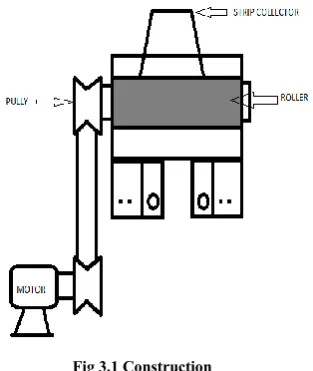
3.1 Construction
The below figure shows the constructional details of a “Tablet Strip Defoiling Machine”. A machine consists of various parts such as shaft, bearing, motor, pulley, belt and blade disc.
Fig 3.1 Construction
The motor mounted on frame structure on base plate. This drives the shaft with the help of pulley. There are two rotating shafts, which mounted on channel. The upper rotating shaft has a special type of rubber roller and on the lower shaft the blade disc is mounted.
3.2 Working
1.Motor- The most common unit a designer recommends to drive the load is an electric motor. An electric motor is an electrical machine that converts electrical energy into mechanical energy. 2.Belt- A V belt used which is a loop of flexible
material used to mechanically link two or more rotating shafts, most often parallel. Belts may be used as a source of motion, to transmit powerefficiently, or to track relative movement.
3.Pulley-A pulley is a wheel on an axle or shaft that is designed to supportmovement and change of direction of a belt along its circumference. Pulleys are used in a variety of ways to lift loads, apply forces, and to transmit power.
4.Shaft –It is a mechanical component for transmitting torque and rotation, usually used to connect other components of a drive train that cannot be connected directly because of distance or the need to allow for relative movement between them.
5.Disc –The disc plates on the lower shaft which is used as a cutting as gear and also transmit the rotary motion between two shafts.
It is a simple machine to recover tablets / capsules from damaged or incomplete blister packs. A damaged or incomplete pack is inserted between two guides and pushed manually inside it.
Problem Identification
Literature survey
Design of machine mechanism
Select standard parts
Manufacturing each component and construct
the setup
Conduct the experiments
[image:2.595.103.244.250.633.2]International Journal of Emerging Technology and Advanced Engineering
Website: www.ijetae.com (ISSN 2250-2459, ISO 9001:2008 Certified Journal, Volume 6, Issue 4, April 2016)
221
Three adjustable wheels grips and draws the pack under a rubberized roller. The rubber roller presses down on the blister cavities-pushing out the product. The machine is adjustable to suit most pack sizes. The machine is suitable to open aluminium foil as well as glassine foil. Removed open tablets is collected in a box or container and packaging material is collected at the back. By proper adjustments of wheels, guides and pressure of rubber roller a high rate of recovery can be achieved. Machine is constructed from stainless steel and is mounted on castor wheels.
IV. MECHANICAL DESIGN
In mechanical design the components are listed down and stored on the basis of their procurement, design in two categories namely.
1. Designed parts 2. Parts to be purchased
Mechanical design phase is very important from the designer point of view as whole success of project depends on the correct design analysis of the problem. Many preliminary alternatives are eliminated during this phase. Designer should have a adequate knowledge about its physical properties of material, load stresses and failure occur. He should identify all internal and external forces acting on machine parts.
These forces may be classified as, a) Dead weight forces
b) Friction forces c) Inertia forces d) Centrifugal forces
e) Forces generated during power transmission etc. Designer should estimate these forces very accurately by using design equations. If he does not have sufficient information to estimate them he should make certain practical assumptions based on similar conditions which will almost satisfy the functional needs. Assumptions must always be on the safer side. Selection of factors of safety to find working or design stress is another important step in design of working dimensions of machine elements. The correction in the theoretical stress values are to be made according in the kind of loads, shape of parts & service requirements. Selection of material should be made according to the loading condition, shapes of products, environment conditions & desirable properties of material provision should be made to minimize nearly adopting proper lubrications method.
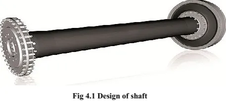
4.1 Design of Shaft:
A shaft is a rotating element which is used to transmit power from one place to another place.
[image:3.595.320.549.192.295.2]The power is delivered to the shaft by some means of tangential force and the resultant torque set up within the shaft permits the power and motion to be transferred to various machines linked up to the shaft.
Fig 4.1 Design of shaft
In order to transfer the power from one shaft to other, the various members such as pulleys, gears, etc. are mounted on it. These members along with the forces exerted upon them causes the shaft bending.
4.1.1 Material used for shaft
1. It should have high strength and toughness. 2. It should have good machinability.
3. It should have good heat treatment properties. 4. It should have high wear resistance properties The material used for ordinary shafts is carbon steel of grades 40C8, 45C8, 50C4 &50C12. Also M.S. & En8 can be used.
4.1.2 Stresses in shafts
1. Shear stress due to transmission of torque. (i.e. due to torsional load.)
2. Bending stresses (tensile or compressive) due to the forces acting on the machine elements like gears, pulleys etc. as well as due to the self-weight of the shaft.
4.1.3 The shafts are designed on the following basis Strength and Rigidity:
The following cases may be considered.
a) Shaft subjected to twisting moment or torque only.
b) Shaft subjected to bending moment only. c) Shaft subjected to combined bending &
twisting moment.
d) Shaft subjected to axial loads in addition to combine torsional & bending.
4.1.4 ASME code for design of shaft:
International Journal of Emerging Technology and Advanced Engineering
Website: www.ijetae.com (ISSN 2250-2459, ISO 9001:2008 Certified Journal, Volume 6, Issue 4, April 2016)
222
[image:4.595.318.543.120.318.2]According to ASME code permissible values of shear stress may be calculated from various relations.
Table no 4.3.3 Material Properties
Designation UTS
(N/mm2) Yield Strength (N/mm2)
C40 600 N/mm2 380 N/mm2
f (allowable) = 0.18 F(ut) = 0.18×600 = 108 N/mm2 OR
f(actual) = 0.3 F(yt) = 0.3 × 380 = 114 N/mm2
By considering minimum of the above values Fs (allowable) =108 N/mm2
This is allowable value of shear stress that can be induced in shaft material for safe operation.
Hence design is considered as safe.
4.1.5 Check for Torsional Shear Failure of Shaft
Assuming minimum section diameter on input shaft = 20mm
d=20mm Td =π/16*Fact Fact=16*Td/πd3 Fact=30.39 N/mm2
as Fact is less than f(actual)
Input shaft is safe under torsional load.
Hence we have selected bearing of 20mm bore diameter.
4.2 Bearing And Housing
[image:4.595.47.276.165.331.2]A bearing is a mechanical element which is used to support the rotating parts and confines its motion. The supporting member is usually designated as bearing and it may be a journal. Since there is a relative motion between the bearing and the rotating element, a certain amount of power must be absorbed in order to overcoming friction, and if the surface actually touches, there will be a rapid wear. Shafts are generally supported by two bearings in the radial and axial directions.
Fig 4.2 Bearing
The bearing selected for the design where Deep groove ball type bearing which have good load carrying capacity and it can accommodate misalignment bearings of 20mm bore diameter were selected for the design; it was ensured that bearings would allowed for the mounting of all components onto the shaft physically and that the mass of all components including bearings was minimized. These bearings provide coefficient of friction in between 0.001 to 0.002. These bearings offer advantages like rapid replacement, less space requirement and warning of failure with increasing noisiness.
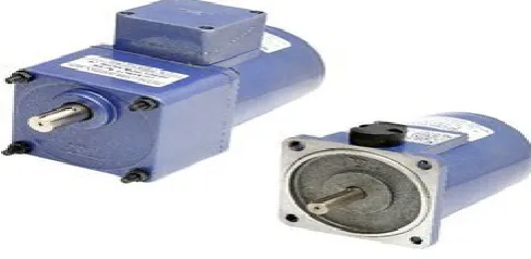
4.3 Motor:
Electric motor is an electric device which is used to convert electrical energy into the mechanical energy. In normal motoring mode, most electric motors operate through the interaction between an electric motor’s magnetic field and winding currents to generate the force within the motor.
[image:4.595.315.559.559.678.2]International Journal of Emerging Technology and Advanced Engineering
Website: www.ijetae.com (ISSN 2250-2459, ISO 9001:2008 Certified Journal, Volume 6, Issue 4, April 2016)
223
There are two types of motors: 1) AC motor 2) DC motor
We are using DC motor. Torque provided by motor is required only to start the rotation of shaft with the help of belt and pulley drive because of this small requirement of torque we are using dc motor of less power input.
4.3.1 Specification
1. Voltage: 12 volt 2. Current: 5amp 3. Speed: 50-100 rpm 4. Weight: 3.75kg
4.3.2 Motor design
Given data: Speed (N) = 50 rpm Force = 3.75 kg
Distance = 440 mm FOS = 1.5 Force = 4× 9.81 = 39.24N
Torque = Force × Distance = 39.24 × 440 = 17265.6 N-mm = 17.26 N-m Therefore,
Maximum Torque = 17.26 × 1.5 = 25.89N-m Now,
Power = P =2πNT/60 =2π*50*25.89/60 = 135.5 watts. Therefore,
Selecting motor power of 125 watts so losses can be avoided.
4.3.3 To Calculate Input Torque
Let,
Power = P =2πNT/60 125 = 2π*50*T/60 T = 23.87 N-m Assuming 100% overload T(design) = 2 × T
= 2 × 23.87 ×103 = 47.74 × 10³ N-mm
V. CONCLUSION
Pharmaceutical tablets are most critical and essential to the importance of human life. The tablet strip defoiling machine plays an important role to increase the productivity by reducing a time required to defoil a tablets by hand work. The our project Semi-Automatic Defoiling Machine have designed on experimental basic and so adopted and chooses all channels that assure quality. The present that we have developed is capable of overcoming all the drawbacks of previous and in addition will provide extra utilities such as better space utilization, easy to handled etc.
REFERENCES
[1] V.B. Bhandari/ “Design of machine elements”, Tata McGraw Hill
Pub Co. Ltd, EditionOct 2008.
[2] S.Sathiyamoorthy1 1Project Scientist IV, NHHID, Anna
University, Tamil Nadu, India
[3] Pinnamaneni Bhanu Prasad Advisor, KELENN Technology,
France Computer Science & Engineering, Rajalakshmi Engineering College, Chennai, India
[4] “Design Data Book”, P.S.G. collage of technology, Coimbatore,
edition oct.2003.
[5] Haideri. “Mechanical system Design/ Nirali publication Edition
2009.
[6] R.B. patil/ “transmission System Design”, Tech-max publication,
pune, Edition 2009.
[7] C.V.S.Subrahmanyam “Pharmaceuticals EngineerinBook”,
VallabhPrakashan, Edition Third, 1997.