International Journal of Emerging Technology and Advanced Engineering
Website: www.ijetae.com (ISSN 2250-2459,ISO 9001:2008 Certified Journal, Volume 4, Issue 12, December 2014)
351
Mitigation of Low Frequency Oscillation Phenomenon in
Power System by Implementing Adaptive Fuzzy Logic
Controlled Power System Stabilizer
Vivek Saxena
1, Rajeshwari CS
2, Satya Prakash
31,3SKNSITS, Lonavala, India 2
National Institute of Technical Teachers Training & Research, Bhopal, India
Abstract— The power system stabilizer is used to damp out the low frequency oscillations that improve the small signal stability of the power system. If ignored these low frequency oscillations may lead to cascaded failure of the complete power system. This paper presents the comparative study of conventional power system stabilizer (CPSS) with newly proposed Adaptive Fuzzy Logic Controlled Power System Stabilizer (AFLCPSS) for mitigation of low frequency oscillation phenomenon in Power system.
Keywords— Small signal stability, Low frequency
oscillations, Power system stabilizer, Adaptive Fuzzy Logic Controlled Power System Stabilizer.
I. INTRODUCTION
The prime objective of power system is to generate the electrical energy from the naturally available sources of the energy & then transport it reliably to the point of consumption using transmission network. The major limitation of electrical energy is that it cannot be stored in bulk and hence it is generated as per the demand which is highly unpredictable in nature. Therefore it is important to maintain the balance between the generation & demand of electrical energy. The modern power have grown complex due to extensive interconnection between various generating stations & grids and it operates under extreme stressed conditions i.e. close to its operating limits. This interconnection of grids has improved the reliability of operation of power system but at the same time it has made the power system susceptible to instability related problems.
In large power system all the generators operate in synchronism to maintain the same frequency which is in turn is synchronized to rotor mechanical speed. The sudden change in load, loss of generating unit or loss of weak tie line disrupts this synchronized operation as some machine speeds up while other slows down to regain its state of operating equilibrium. This phenomenon is also known as rotor swinging [9]. It needed to implement some kind of control strategy for maintaining this swing within allowable limits or else the generator will fall out of synchronism.
Hence to overcome this problem the automatic voltage regulator (AVR) was introduced in power system.
AVR provides the coarse adjustment by controlling the first swing & keeps the electrical speed of the generators within the acceptable limit however the AVR is unable to control the oscillations in speed also known as low frequency oscillations (LFO) [8]. The power system stabilizer was introduced at generators to damp out these low frequency oscillations.
These power system stabilizers are tuned to particular operating condition of the power system. The performance of conventional power system stabilizer degrades with change in operating conditions of power system. The PSS should adaptive to dynamic operating conditions of system & maintain optimum performance. However various approaches have been suggested for tuning power system stabilizer to obtain the optimized performance such implementation of genetic algorithm, particle swarm optimization, artificial neural network, evolutionary program etc. [2],[3],[4],[5],[7],[11],[12]. This paper emphasizes on application of fuzzy logic in designing new power system stabilizer which is self tuned & adaptive to dynamic operating conditions of the power system. This power system stabilizer will hence forth will termed as Adaptive fuzzy logic controlled power system stabilizer (AFLCPSS).
II. LOW FREQUENCY OSCILLATIONS (LFO):
The synchronous machine consists of two essential elements, the field winding placed on rotor & the armature winding placed on stator. When the rotor which houses the dc current excited field winding is rotated by prime mover, it induces the alternating voltages in the three phase armature winding. The current starts flowing in the armature winding as soon as load is connected across the synchronous machine output terminals. The frequency of induced voltage & the current is dependent on the speed of the rotor or it can be said that the frequency is synchronized to mechanical speed of the rotor. The stator current produces a revolving stator field which rotates at synchronous speed in air gap. It interacts with the revolving rotor field & exerts a torque which opposes the rotation of rotor. This torque is known as
International Journal of Emerging Technology and Advanced Engineering
Website: www.ijetae.com (ISSN 2250-2459,ISO 9001:2008 Certified Journal, Volume 4, Issue 12, December 2014)
352
The steady state is the equilibrium between these two opposing torques. Any fault or disturbance changes the electromagnetic torque and upsets this equilibrium. This results into acceleration or deceleration of the rotor. In multi machine power system, if the rotor of one machine runs faster than other its position relative to that of slower machine advances, as a result a part of load if transferred to faster machine in a bid to restore the equilibrium. The transfer of load from one machine to another is governed by the power-angle relationship which is highly non linear. Beyond the certain limit the power transfer capability decreases & increases the angular separation between the rotors of the machine. This further leads to instability [13].The change in electromagnetic torque following perturbations can be resolved into two components as follows:
Synchronizing torque: This torque is in phase with rotor angle deviation.
Damping torque: This torque is in phase with speed deviation.
The lack of sufficient synchronizing torque leads to non-oscillatory instability while the lack of damping torque leads to low frequency oscillations of range 0.1-2Hz. The use of fast acting AVR increases the synchronizing torque for coarse adjustment during first swing but it reduces the damping torque & leads to instability due to low frequency oscillations. The LFO can be classified as local mode or inter area mode. To damp out these LFOs, the power system stabilizer is installed which increases the damping torque at the time perturbations. The conventional power system stabilizer performs well for the steady state operating condition for which they are tuned & designed. Once the operating condition changes the performance of CPSS degrades.
III. HEFFRON PHILIPHS MODEL
[image:2.595.317.549.110.295.2]For analysing of performance of power system stabilizer the single machine connected to infinite machine (SMIB) system has been taken into consideration. The Heffron philiphs model represents the linearized model of synchronous machine which is suitable for stability study. This model is based on third order model of synchronous machine as shown in Figure1 [6].
Figure 1 Heffron Philiphs model of single machine connected to infinite bus (SMIB)
IV. CONVENTIONAL POWER SYSTEM STABILIZER
The conventional power system stabilizer is an auxiliary device that is used to produce the component of electrical torque in phase with rotor speed deviations. It damps out the generator rotor oscillations by controlling AVR excititation using auxiliary stabilizing signal.
It provides supplementary feedback stabilizing signal in the excitation system. The feedback is implemented in such a way that electrical torque on the rotor is in phase with speed variations [13].
The conventional power system stabilizer can utilize any of the following signals as their input:
The shaft speed deviation, ∆ω
Active power output, ∆Pa
Change in electric power, ∆Pe
Bus frequency, ∆f
The block diagram of conventional power system stabilizer consists of following blocks:
Gain: It determines the amount of damping introduced by the stabilizer
Washout: It is a high pass filter that responds only to oscillations in speed & blocks the dc offset
International Journal of Emerging Technology and Advanced Engineering
Website: www.ijetae.com (ISSN 2250-2459,ISO 9001:2008 Certified Journal, Volume 4, Issue 12, December 2014)
353
Limiter: The output of the power system stabilizer is required to be limited in order to prevent conflicts with AVR actions during load rejection. The block diagram of conventional power system stabilizer is shown in Fig.2
[image:3.595.45.277.216.295.2]In this paper the shaft deviation or angular position & the acceleration has been taken as an input for CPSS.
Figure 2.Bock diagram of conventional power system stabilizer
V. FUZZY LOGIC
[image:3.595.325.536.243.323.2]The fuzzy logic mimics the human reasoning which is approximate in nature. Fuzzy logic is a derived from classical Boolean logic and implements soft linguistic variables on a continuous range of truth values to be defined between conventional binary i.e. (0, 1). It is capable to handle approximate information in a systematic way and therefore it is suited for controlling non-linear systems and for modeling complex systems where an inaccurate model exists or systems where ambiguity or vagueness is common [1].
Figure 3.Fuzzy Logic System
Fuzzy Logic System: A fuzzy logic system (FLS) can be defined as the nonlinear mapping of an input data set to a scalar output data. A FLS consists of four main parts:
Fuzzifier
Rules
Inference engine
Defuzzifier.
VI. ADAPTIVE FUZZY LOGIC CONTROLLED POWER
SYSTEM STABILIZER (AFLCPSS)
The adaptive fuzzy logic controlled power system stabilizer utilizes the speed and acceleration as its input [10]. Hence there are two input variables & one output variable defined for fuzzy logic controller. In this logic controller triangular membership function is used to define the degree of membership function. The member functions are decided to transform the input/output variables into linguistic variables.
The member function maps the crisp values into fuzzy variables as shown in Fig 4, Fig 5 & Fig 6.
There are seven linguistic variables defined for each input & output variables as follows:
LN (Large Negative), MN (Medium Negative), SN (Small Negative), Z (Zero), SP (Small Positive), MP (Medium Positive), LP (Large Positive)
[image:3.595.319.543.377.475.2]Membership function for speed deviation (i/p):
Figure 4.Triangular membership function defined for Speed Deviation
[image:3.595.33.285.468.558.2]Membership functions for acceleration (i/p):
Figure 5. Triangular membership function defined for Acceleration
Membership function for voltage (o/p):
Figure 6. Triangular membership function defined for Voltage
[image:3.595.330.536.521.596.2] [image:3.595.309.578.620.750.2]International Journal of Emerging Technology and Advanced Engineering
Website: www.ijetae.com (ISSN 2250-2459,ISO 9001:2008 Certified Journal, Volume 4, Issue 12, December 2014)
[image:4.595.39.285.114.408.2]354
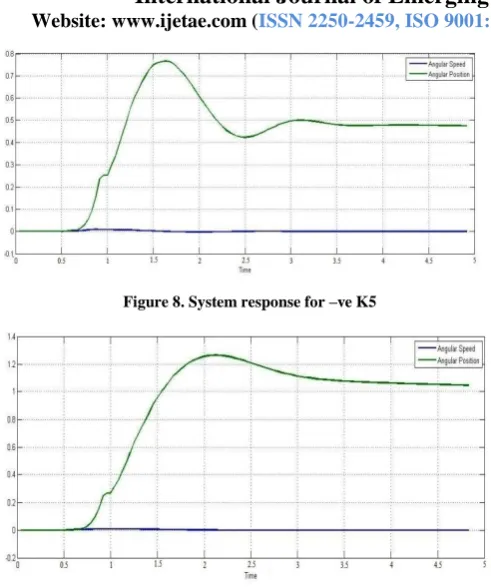
Figure 8. System response for –ve K5
Figure 9. System response for +ve K5
VII. SIMULATION &RESULTS
Case I: Performance of system with Conventional lead lag power system stabilizer
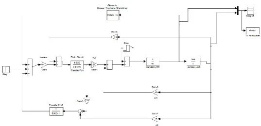
[image:4.595.304.562.125.388.2]The Fig 7 shows the Simulink model of SMIB installed with conventional power system stabilizer
Figure 10. SMIB installed with Adaptive Fuzzy Logic Controlled Power System Stabilizer
Figure 11. System response for –ve K5
Figure 12. System response for + ve K5
Case II: Performance of system with Adaptive Fuzzy Logic Controlled Power System Stabilizer
The Fig 10 shows the Simulink model of SMIB installed with adaptive fuzzy logic controlled power system stabilizer
[image:4.595.34.286.512.653.2]The inference engine executes the 7X7 rules that govern the relationship between input & output as shown in Table 1.
TABLE 1 DECISION TABLE
Acceleratio
n LN MN SN Z SP MP LP
Speed
LN LN LN LN LN SN SN Z
MN LN LN M
N M
N
SN Z SP
SN LN M
N M
N
SN Z SP M
P
Z M
N M N
SN Z SP M
P M
P
SP M
N
SN Z SP M
P M
P LP
MP SN Z SP MP M
P
LP LP
LP Z SP MP LP M
P
[image:4.595.307.553.517.678.2]International Journal of Emerging Technology and Advanced Engineering
Website: www.ijetae.com (ISSN 2250-2459,ISO 9001:2008 Certified Journal, Volume 4, Issue 12, December 2014)
355
A. Fuzzy Inference System:
For the designing the fuzzy logic controller the fuzzy inference system (FIS) is implemented using Mamdani type rule base model
VIII. CONCLUSION
The objective of this paper was to inspect the effectiveness of the conventional lead lag power system stabilizer connected to single machine infinite bus system in damping out the low frequency oscillations. The conventional lead lag power system stabilizer utilizes the speed deviation as an input. It can be observed from Fig. 8 & Fig.9 that the performance of CPSS is satisfactory & system is stable for –ve & +ve values of K5.However the transients are more prominent for –ve K5 as shown in Fig.8, whereas higher angular position is attained for +ve K5. Then new adaptive fuzzy logic controlled power system stabilizer is proposed for enhancing the performance of CPSS. It utilizes the speed deviation & acceleration as an input to power system stabilizer. It gives the voltage as the output signal.
The newly proposed Adaptive Fuzzy Logic Controlled Power System Stabilizer produces better damping effect in comparison to Conventional Power System Stabilizer & stabilizes the system quickly as it is evident from Fig.11 & Fig.12. In comparison to Fig.8 & Fig.9 the rising & settling time has been decreased significantly in Fig.11 & Fig.12. Therefore it can be concluded that Adaptive Fuzzy Logic Controlled Power System Stabilizer shows far better performance than the Conventional Power System Stabilizer.
REFERENCES
[1] K. Tomsovic, M.Y. Chow ―Tutorial on Fuzzy Logic Applications in Power Systems‖, Prepared for the IEEE-PES Winter Meeting in Singapore January, 2000
[2] M. A. Abido,‖Optimal Design of Power–System Stabilizers Using Particle Swarm Optimization‖ IEEE Transactions On Energy Conversion, Vol. 17, No. 3, September 2002
[3] Y. L. Abdel-Magid, Senior Member, IEEE, and M. A. Abido, Member, IEEE ,―Optimal Multiobjective Design of Robust Power System Stabilizers Using Genetic Algorithms‖, IEEE Transactions On Power Systems, Vol. 18, No. 3, August 2003
[4] Ravi Segala, Avdhesh Sharmab, M.L. Kotharic,‖A self-tuning power system stabilizer based on artificial neural network‖, Electrical Power and Energy Systems 26 (2004) 423–430, Elsevier
[5] Manisha Dubey, Pankaj Gupta,‖Design of Genetic-Algorithm Based Robust Power System Stabilizer‖,International Journal of Information and Mathematical Sciences 2:1 2006
[6] Prathap Hari Krishna, B N S P Venkatesh ,―Design Of Power System Stabilizer To Improve Small Signal Stability By Using Modified Heffron-Phillip’s Model‖, International Journal of Engineering Science and Technology (IJEST)
[7] Ravindra Singh, ―A novel approach for tuning of Power system stabilizer using genetic algorithm‖, Department of Electrical Engineering Indian Institute Of Science, Bangalore, thesis submitted for the degree of Master, July 2004.
[8] F.P. deMello, C. Concordia, ―Concept of synchronous machine stability asaffected by excitation control‖, IEEE trans. Power Appr. Syst. 88, 1969, 316 –329.
[9] M. Klein, G.J. Rogers, P. Kundur, ―A fundamental study of inter – area oscillation in power systems,‖ IEEE Trans. Power system, 1991, pp.914 – 921.
[10] Juan Shi, Herron L.H and Kalam A, ―Application of Fuzzy Logic controller Power System Stabilization‖, Victoria University of Technology, Australia, IEEE TENCON, 2002, Beijing.
[11] M.A. Abido and Y.L. Abdel – Magid, Sentor member ―Optimal design of power system stabilizers using Evolutionary Programming‖. IEEE transaction on energy conversion, vol. 17, NO.4, December 2002.
[12] A.M. El-Zonkoly *, A.A. Khalil, N.M. Ahmied A.M. El-Zonkoly *, A.A. Khalil, N.M. Ahmied, ―Optimal tunning of lead-lag and fuzzy logic power system stabilizers using particle swarm optimization‖, Expert Systems with Applications 36 (2009) 2097– 2106, Elsevier
[13] P. Kundur, Power System Stability and Control, Mc Graw – Hill, New York, 1994.
[14] Manish Kushwaha, Mrs. Ranjeeta Khare, ―Improvement of Dynamic Stability of a SMIB using Fuzzy Logic Based Power System Stabilizer‖, International Journal of Engineering Research and Applications (IJERA) ISSN: 2248-9622 www.ijera.com Vol. 2, Issue 6, November- December 2012, pp.1429-1439
[15] Rahul Malhotra1, Rajinder Sodhi2, ―Boiler Flow Control Using PID and Fuzzy Logic Controller‖, IJCSET | July 2011 | Vol 1, Issue 6,315-319
[16] Mr. Polamuri Pradeep1, Mr.N.Vamsi Krishna2,‖ Analysis of Power System Stabilizer Using Fuzzy Logic Controller‖, International Journal of Engineering Research & Technology (IJERT) Vol. 1 Issue 5, July - 2012
[17] A.M. El-Zonkoly *, A.A. Khalil, N.M. Ahmied, ―Optimal tunning of lead-lag and fuzzy logic power system stabilizers using particle swarm optimization‖, Expert Systems with Applications 36 (2009) 2097–2106,Elsevier, 2009