44
Chapter
6
Regulation of 12-pulse Rectifier Converter using ANFIS-based Controller in a
HVDC Transmission System
I Made Ginarsa1,a, Agung Budi Muljono1,b, I Made Ari Nrartha1,c, Osea Zebua2,d
1
Department of Electrical Engineering, Mataram University, Mataram 83125, Indonesia
2
Dept. of Electrical Engineering, University of Lampung, Jln. Sumantri Brojonegoro, Bandar Lampung [email protected],b [email protected],[email protected],[email protected]
Abstract. High voltage direct current (HVDC) transmission is a better prospect choice compared to high
voltage AC transmission. The HVDC is able to apply higher voltage level and without any reactive power losses. By supporting power electronic technology, the HVDC is simpler and cheaper to be realized. So, the problem in the HVDC system is how to control power flow in rectifier converter device effectively. In this research, regulating of firing delay angle is proposed by ANFIS-based controller (ANC) in 12-pulse rectifier. The ANC is applied because computation of the ANC is more effective than Mamdani fuzzy controller computation. The ANC is trained by data-learning in off-line mode. In normal operation, the maximum transmitted power by the HVDC is on the value of 1.0 pu with voltage and current DC at 1.0 pu when the firing delay angle at 26o. Also, the ANC is able to compensate temporary short-circuit fault.
Keywords. ANFIS, controller, firing delay angle, HVDC, rectifier.
I.
Introduction
High voltage direct current (HVDC) transmission system is usually used to deliver bulk of electric power over a long distance area by overhead conductors or submarine cables. The HVDC system has several advantages compared to high voltage alternating current (HVAC) system such as: location of electric power production are very far from location of consumer, long distance HVDC system do not need reactive power compensation as required by long distance of the HVAC system, to make an asynchronous interconnection and allows more capacity of power to be transmitted/delivered [1] [2]. Also, for a given conductor cross section, the HVDC transmission system can carry more current through this conductor compared to a conventional HVAC system[1].
45
Analytical method to calculate the efficiency of two and three-level VSC with average and root mean square of converter current is used to the HVDC system. This method is applied to estimate the losses of DC cable, coupling transformer, AC harmonic filter and conduction – switching at the converter. The analytical method and measuring software technique are compared in order to validate of the results [5]. Moreover, power flow strategy with multi-objective optimization for multi-terminal HVDC grid [6] is done by Carrizosa et al. Line commutated rectifier (LCC) and modular multi-level converter (MMC) are applied in hybrid HVDC topology to clear DC fault. Where, the LCC is adopted as rectifier side and the 2 (two) MMC moduls are adopt as inverter side. This topology is able to block current fault path by alpha-retard(α-retard) of the LCC and high power diode. Also, the system is able to restart after clearance of transient DC line fault [7]. A novel rapid protection whole-line principle to protect the HVDC transmission lines using oneend voltage signal was proposed in [8]. Where, this proposed protection method works by analysing measured voltage of the electric network to identify and distinguish between internal or external faults. Moreover, the proposed method operates rapidly, selectively and with high accuracy, under different fault conditions. Natural frequency of distributed parameter line model is applied to determine the fault location on light HVDC system [9]. Using spectral analysis of current by the prony algorithm, a short data window is sufficient to detect the natural frequency and fault location accurately. It is found that the accuracy of fault location over entire HVDC transmission line is not affected by fault resistance and fault type.Some intelligent control such as: Neural network (NN), fuzzy and neuro-fuzzy control are applied successful in electrical and other engineering fields to replace the function of conventional control scheme in recent years. Proportional integral derivative-static var compensator (PID-SVC) based on recurrent NN has been applied to control chaos and voltage collapse in critical loading of a power system [10]. Moreover, ANFIS-based composite controller-SVC and PID-loop have been applied to control chaos, voltage collapse, and to regulate the load voltage at load bus. In this control scheme, the load bus is varied. In order to maintain the load voltage on the setting value, the reactive power compensation is provided by the SVC [11] [12]. ANFIS controller is applied to control and fault identification in converter of HVDC system. Where, this controller is able to improve dynamic response of the system [13]. Furthermore, ANFIS-based power system stabilizer has been applied to improve the stability of single machine based on feedback linearisation [14]. In this research, we focus on controlling rectifier of HVDC using ANFIS-based controller to replace the conventional controller. This paper is organized as follows: High voltage direct current (HVDC) is described in Section II. ANFIS-based rectifier controller design is detailed in Section III. Next, simulation result and analysis are presented in Section IV. And, the conclusion is provided in the last section.
II.
HVDC Transmission Model
The advantage of HVDC is the ability to control the transmitted power rapidly. Proper design of the HVDC control is essential to ensure satisfactory performance of the overall AC/DC transmission systems [15]. Some aspects of power flow control in HVDC using flexible AC transmission system are described in [16] [17].
Consider a DC transmission system to be compared with a 3-phase AC system transmitting the same power, having the same percentage losses and using the same size conductor. Where the DC system is considered to have 2 (two) conductors at Vdto earth. These formulas are as follows [1]: Power in the AC system (Pa= 3EphIL
2 2
assumed that cosϕ = 1.0), power in the DC system (Pd = 2VdLId), AC losses (3ILR) and DC losses (2IdR).
Equating line losses,
46
equating powers, [image:3.595.100.530.148.273.2]where Eph, IL, Pa, VdL, Id, Pdand R are the AC voltage phase to neutral, AC line current, 3-phase AC real power, DC voltage, DC current, DC power and line resistance, respectively.
Fig. 1. Model of HVDC transmission system
The HVDC model in this research is taken from [18] and is shown in Fig. . 1. The system consist of 4 buses, step-up/down transformer, 3-phase rectifier/inverter, RL series branch and 300 km long HVDC transmission. Bus parameters are as follows: Bus 1 consist of AC source with third harmonic, 5000 MVA equivalent, 500 kV, 80◦, 60 Hz. Bus 2: (Capacitor bank + 11th+ 13th+ 24thharmonic filters)×150 MVAR and 3-phase rectifier. Bus 3: Three-phase inverter and 150 MVAR×(capacitor bank + 11th+ 13th+ 24thharmonic filters). And, Bus 4: AC source with third harmonic, 1000 MVA equivalent, 345 kV, 80◦, 50 Hz. Branch parameters: AC line126.07Ω and
48.86×10⁻³H. The transmission DC line: 6.5Ω, 1.2376 H and 4.32×10⁻⁶F. And, the transmission AC line2: 6.205Ωand 13.96×10⁻³H.
III.
ANFIS-Based Control Design
Rectifier Converter and Its Controller
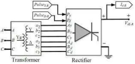
Rectifier converter is very important in HVDC system, that the rectifier converter is used to convert alternating current (AC) to direct current (DC). Therefore, the DC will be transmitted from sending-end to receiving-end through HVDC transmission system. Fig. 2 shows the 12-pulse firing controller unit of the rectifier converter. The controller unit produced PulseY−R to trigger the respective thyristor-gate at 3-phase AyByCy in star (Y)
connected. Also, this controller unit produced PulseD−R to fire respective thyristor-gate at 3-phase AdBdCdin
delta (∆) connected. Moreover, the voltage/current from the both star and delta connected were used to generate DC voltage (VdL−R)/current (Id−R) in the DC side of the rectifier. In order to regulate the level of
voltage/current rectifier converter is proper to appropriate of demand side needed, it is convenient to provide this rectifier converter by the controller unit.
[image:3.595.187.423.627.739.2]47
The main function of rectifier controller unit is to produce firing delay angle (αord) signal. This signal is fed tothe 12pulse firing control of the respective thyristor-valve in bridge converter. So, the 12-pulse firing controller generates trigger pulse, that this trigger pulse is used to on/off the thyristor-gate. Furthermore, this controller also produces two other output signals such as: Reference current (Idref) and mode operation (Mode) of rectifier.
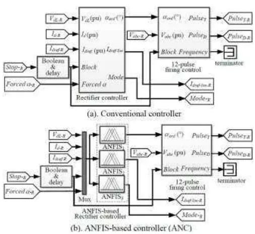
The diagram block of conventional rectifier controller is shown in Fig. 3(a). Reference current (Idref) is used as the
target current level of rectifier, where the DC line current (Id) should follow the (Idref) on every time. And, the
[image:4.595.177.430.192.424.2]control mode is used to classify the operation of the rectifier into Mode 0: blocked mode, 1: current, 2: voltage , 3:αmin, 4:αmax, 5: forcedαand Mode 6:γmode.
Fig. 3. Diagram block of 12-pulse rectifier controller
Training of ANFIS-based Controller
Before ANFIS-based controller (ANC) is applied to the HVDC converter, that the ANC is trained in some training processes. The data that used on training process were obtained by simulating the conventional controller. The conventional controller is shown in Fig. 3(a). On this training process, a 4000-data point was used to learn the ANFIS controller. Input of the ANC was 5 (five) input variables such as: VdL, Id, Idref, block and forcedα. Three
(3) ANFIS models were used to implement the rectifier controller such as: ANFIS1, ANFIS2and ANFIS3. The output of respective ANFIS model were theαord, Idref−R and mode operation of the rectifier (Mode R). The ANC
diagram block of the rectifier converter is shown Fig. 3(b).
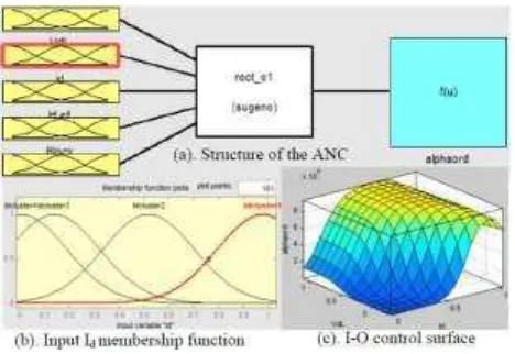
In this research only the ANFIS1topic is described, meanwhile ANFIS2and ANFIS3are not discussed. Structure of ANFIS controller was built by 5 (five) inputs Sugeno fuzzy model and 1 (one) output as shown in Fig. 4(a). The training process was conducted in off-line session and subtractive clustering method was used to generate fuzzy inference system (FIS). In this session, some parameters such as: Range of influence = 0.5, squash factor = 1.5, accept ratio = 0.5 and reject ratio = 0.15 were taken. Every input variables were consist of 4 (four) Gaussian membership functions, the Idinput was taken as example and shown in Fig. 4(b). After some training processes
were conducted, control surface of respective input-output controller was obtained automatically. This session produced ten (10) sets of input-output control surface of the ANC. An example of the input-output control surface is a DC line voltage-DC current-firing delay (VdL-Idαord). So, this control surface is shown in Fig.
48
Fig. 4. Parameters of the ANFIS-based controller (ANC).Table 1. Performance Of Anfis Controller At Normal Operation
IV.
Simulation and Analysis
To demonstrate the performance and applicability of the proposed controller, the HVDC system equipped by that controller was examined using Matlab/Simulink 7.9.0.529 (R2009b) [19] on an Intel Core 2 Duo E6550 233 GHz PC computer and windows 7 64-bit (win64) operating system. The simulations were done as follows:
A. Performance of ANFIS-based Controller at Start/stop and Ramp-up/down
49
Fig. 5(a) and Table I show the firing delay angle (αord) control at this scenario. In this graphical result theαordforconventional controller (CVC) was added by 20◦to differentiate theαordfrom the ANC result. It is shown that
theαordwas started at 90
◦
. Next, theαordincreased to 92
◦
at time t0.
So, theαorddecreased to 30◦at time t1and decreased again to 26◦until time 1.2 s. Theαordincreased to 40◦at time
t2, and increased again to 166◦at time t3. Fig. 5(b) shows the mode operation of rectifier in this scenario. Firstly, the rectifier was operated in Blocked Mode from time 0.0 s until time t0, and the Blocked Mode operation was changed to Current Mode at time t0until 1.1 s. So, at time 1.1 s the rectifier was operatedαminMode until time
1.25 s. Next, the rectifier was on Current Mode again until time t3and at time t3the rectifier operated was on ForcedαMode until t4. Finally, the rectifier was operated at Blocked Mode from time t4to infinite time.
Fig. 6(a) and Table II show that VdL increased at the values from 0.05 to 1.06 pu at times from t0 to t1,
respectively. So, the VdLdecreased from 1.06 to 1.0 pu at times from t1to t2. Next, the VdLdecreased again from
1.0 to 0.96 pu at times from t2to t3, respectively. Finally, the VdLdecreased again from 0.96 to 0.25 pu at times
from t3to t4. Fig. 6(b) shows DC line current (Id) compared to reference current (Idref). Firstly, at time t0the Id
was at the value of 0.04 pu until time t1. So, the Idincreased from 0.04 to 0.4 pu at time 4.0 s and increased
again from 0.4 to 1.0 at time from 0.4 to 0.6 s. This Idstill at the value of 1.0 until t2. And, the Iddecreased from
1.0 to 0.0 pu at times from t2to t3.
Fig. 6. The DC line voltage and current at normal operation.
Simulation shows that some results of proposed controller (ANC) in this scenario such as: Firing delay control, mode operation, voltage/current AC input and direct voltage/current output of rectifier are similar to the results of conventional controller (CVC). According to simulation results of the ANC, it is potential to replace the CVC by using ANC permanently. Moreover, to explore ability of the ANC on the HVDC at disturbances/faults condition that the topic will be explained in Scenario 2.
B. Performance of the Controller to cover disturbance/fault
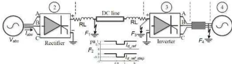
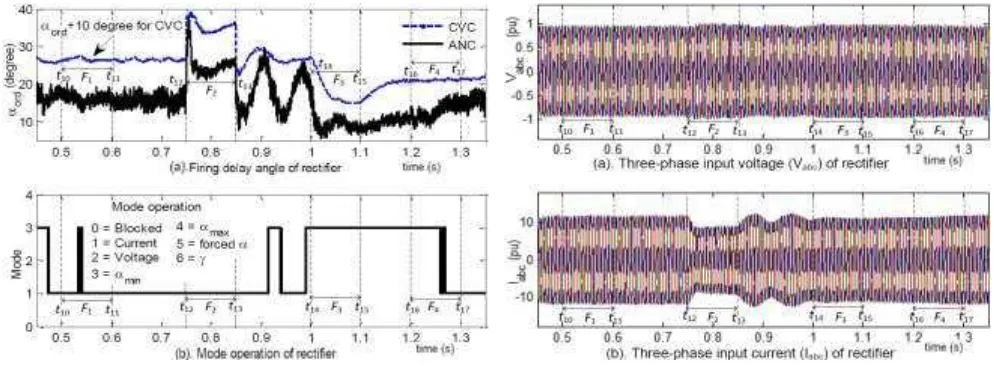
Scenario 2: Four temporary disturbances/faults were forced to the HVDC system on different time. Location and time duration of the respective disturbance/fault are illustrated in Fig. 7. Control strategy of the rectifier to cover disturbance/fault is conducted by regulating the firing delay angle (αord) and by switching mode operation
of this rectifier. Graphical visualization of the αordand mode operation are illustrated in Figs. 8(a) and (b),
respectively. Firstly, positive pole to ground fault occurred at point F1of HVDC line from time 0.5 (t10) to 0.6 s (t11). Theαordwas regulated to the value of 16.5
◦
[image:6.595.186.422.307.492.2]50
In this condition, theαordincreased sharply to 38.6◦
at time t12, then at a moment it was decreased to 16.9◦until time t13. From time t13to time a moment before 1.0 s (t14) it was oscillated from 16.9◦to 10.7◦. Positive pole to ground fault occurred at point F3from time t14to 1.1 s (t15), the αorddecreased to 8.0
◦
at time t14, the αordwas
increased to 11.0◦at time t15, then increased again to 12.0◦before the time 1.2 s (t16). Finally, three-phase fault to ground occurred at AC line2(F4) from t16to 1.3 s (t17), theαordincreased to 12.0◦at time t16, so theαordstayed at
[image:7.595.105.499.145.255.2]this value until time t17. Completeness numerical result of the firing delay angle is listed in Table II.
Fig. 7. The HVDC system is forced by disturbances/faults at F1, F2, F3 and F4 points.
From Fig. 8(b), it is shown that the rectifier was operated onαminMode at time from 0.0 s to 0.2499 s. From time
0.25 to 0.5299 s the rectifier operation was changed to Current Mode, then the rectifier operation was changed again to αminMode from time 0.53 to 0.5499 s. Next, from time 0.55 to 0.9099 the rectifier was on Current
[image:7.595.55.553.354.538.2]Mode, and it was inαminor Mode Current alternately.
Fig. 8. Firing delay angle (αord) and mode operation of HVDC rectifier.
Fig. 9(a) shows the pattern of three-phase voltage input (Vph) of rectifier. The voltage input varied from 0.99 to
0.92 pu for upper limit and lower limit, respectively. Dynamical of three-phase current input (IL) is shown in
Fig. 9(b) and listed in Table II. It is shown that the ILwas at the value of 11.3 pu at time t10, this current
51
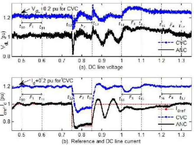
Fig. 9. Dynamical of AC input voltage and current.Fig. 10(a) shows the pattern of DC line voltage (VdL) for the conventional controller (CVC) and ANFIS-based
controller (ANC). It is shown that the time at t10, the VdLwas at the value of 1.0 pu, then this voltage decreased
moderately to 0.99 and 0.98 pu at time t11and until time t12. At time t12, this voltage decreased sharply to 0.822 pu, at a moment this voltage increased to 0.975 pu until time t13. So, at time t13this voltage increased sharply again to 1.15 pu and at a moment this voltage decreased and oscillated to 0.935 pu until t14. At time t14this voltage increased to 1.09 pu until time t15, then this voltage decreased to 1.05 pu until time t16. This voltage decreased again to 1.02 pu at time t16and stayed in this voltage until t17.
Dynamical of the reference current (Idref), DC current (Id) for the CVC and ANC are illustrated in Fig. 10(b). From
Fig. 10(b) and Table II, it is shown that the Idwas at the value of 1.013 pu for time t10, so the Iddecreased at a
moment to 0.995 from time t11to time t12. Next, at time t12the Iddecreased sharply to 0.775 pu, then it increased
moderately to 0.780 until time t13. At time t13, the Idincreased and oscillated from 0.78 to 0.94 pu until time t14,
and at time t14the Iddecreased to 0.77. Then, it increased to 0.945 and increased again to 0.948 pu for time t15and
time t16, respectively. Finally, at the time t16the Idincreased from 0.948 to 1.01 pu until time t17. Simulation results
in this scenario show that the DC currents produced by the CVC and ANC are able to follow the given reference current. The both controllers are working properly and they are giving good performances. Although, the Id
response of the ANC is still oscillate in severe disturbance case such as: When current reference is reduced to−0.25 pu (F2). Some control strategies should be applied to improve the rectifier performance and to anticipate the Id oscillation response when the rectifier is operated in severe disturbances/faults.
52
Fig. 10. Temporal of DC line voltage/current converter.V.
Conclusion
In this research ANFIS-based controller (ANC) is proposed to regulate the firing delay angle of 12-pulse rectifier HVDC. The ANFIS controller is implemented because computation complexity of the ANFIS controller is more efficient than that of fuzzy Mamdani controller. The ANC is built by training processes in off-line session with subtractive clustering method to generate membership function automatically. So, data training of the learning session are provided by simulating the HVDC with conventional controller in varied condition operations. During the learning processes, a 4000-point data set is used to learn the ANC controller per session. The structure of the ANC is built by five signal inputs (DC line voltage, DC current, reference current, block and forced α), and a firing delay angle signal as an output. The respective input of the ANFIS- based controller is represented by Gaussian membership function. Moreover, the output is described by linear membership function. Performance of the ANC is observed on the firing delay angle, mode operation, AC voltage/current input, DC line voltage, and DC current responses, respectively. Simulation results show that the
maximum power conversion is 1.0 pu at the firing delay angle 26◦, the DC voltage and current are at the values of 1.0 pu when the HVDC operated in normal condition. Furthermore, the ANC is also able to cover temporary short circuit AC/DC fault on the HVDC. Meanwhile, the ANC responses are still oscillate when the reference current is reduced. Some efforts should be done to damp the oscillation in the next research.
References
[1]. J. Arrillaga, Y.H. Liu, N.R. Watson, Flexible Power Transmission: The DC Options, John Willey and Son. 1990. pp. 449-454.
[2]. V.F. Pires, J. Fialho, J.F. Silva, ”HVDC transmission system using multilevel power converters based on dual three-phase two-level inverters”, Int. Journal of Elect. Power and Energy Sist., vol. 65, 2015,
53
[3]. X. Tang, D.D.-C. Lu, ”Enhancement of voltage quality in a passive network supplied by a VSC-HVDCtransmission under disturbances”, Int. Journal of Elect. Power and Energy Sist., vol. 54, 2014, pp. 45-54.
[4]. X. Zhang, J. Bai, G. Cau, C. Chen, ”Optimizing HVDC control parameters in multi-infeed HVDC system based on electromagnetic transient analysis”, Int. Journal of Elect. Power and Energy Sist., vol. 49, 2013, pp. 449-454.
[5]. G. Kalcon, G.P. Adam, O. Anaya-Lara, G. Burt, K.L.Lo, ”Analytical efficiency evaluation of two and three level VSC-HVDC transmission link”,Int. Journal of Elect. Power and Energy Sist., vol. 44, 2013,
pp. 1-6.
[6]. M.J. Carrizosa, F.D. Navas, G. Damm, F. Lamnabhi-Lagarrigue, ”Optimal power flow in multi-terminal HVDC grid with offshore wind farms and storage devices”, Int. Journal of Elect. Power and
Energy Sist., vol. 65, 2015, pp. 291-298.
[7]. G. Tang, Z. Xu, ”ALCC and MCC hybrid HVDC topology with DC line fault clearance capability”,
Int. Journal of Elect. Power and Energy Sist., vol. 62, 2014, pp. 419-428.
[8]. S.-p. Gao, X. Chu, Q.-y. Shen, X.-f. Jin, J. Luo, Y.-y. Yun, G.-b. Song, ”A novel whole-line quick-action protection principle for HVDC transmission lines using one-end voltage”, Int. Journal of Elect. Power and Energy Sist., vol. 65, 2015, pp. 262-270.
[9]. S. Guobing, C. Xu, C. Xinlei, G. Shuping, R. Mengbing, ”A fault location method for VSC-HVDC transmission lines based on natural frequency of current”, Int. Journal of Elect. Power and Energy Sist.,
vol. 63, 2014, pp. 347-352.
[10]. I.M. Ginarsa, A.B. Muljono, I.M.A. Nrartha, ”Controlling chaos and Voltage collapse using layered recurrent network-based PID-SVC in power systems”, Telkomnika, vol. 11 (3), 2013.
[11]. I.M. Ginarsa, A. Soeprijanto, M.H. Purnomo,”Controlling chaos and voltage collapse using an ANFIS-based composite controller-static var compensator in power systems”, Int. Journal of Elect. Power and
Energy Sist., 2013, vol. 46, pp. 79-88.
[12]. I.M. Ginarsa, A. Soeprijanto, M.H. Purnomo, Syafaruddin, T. Hiyama, ”Improvement of transient voltage responses using an additional PIDloop on an ANFIS-based composite controller-SVC (CC- SVC) to control chaos and voltage collapse in power systems”, IEEJ Trans. on Power and Energy (Section B), vol. 131 (10), 2011, pp. 836-848.
[13]. N. Bawane, A.G. Kothari, D.P. Kothari, ”ANFIS based control and fault detection of HVDC converter”,HAIT Journal of Science and Engineering B, vol. 2, 2006, pp. 673-689.
[14]. I.M. Ginarsa, O. Zebua, ”Stability improvement of single machine using ANFIS-PSS based on feedback-linearization”,Telkomnika, vol. 12 (2), 2014.
[15]. P. Kundur, Power System Stability and Control, EPRI, McGraw-Hill, New York, 1994.
[16]. X.-P. Zhang, C. Rehtanz, B. Pal, Flexible AC Transmission Systems: Modeling and Control, Springer-Verlag, Berlin Germany, 2006.
[17]. V.K. Sood, HVDC and FACTS Controllers: Applications of Static Controllers in Power Systems, Kluwer Academic Pub, New York USA, 2004.
[18]. S. Casario, Thyristor-based HVDC Transmission System: In Matlab demo, Hydro Quebec Canada, 2009.