The Journal of
Systems and
Software
The Journal of Systems and Software 00 (2013) 000–000
www.elsevier.com/locate/jss
_____________________
* Corresponding author. Tel.: +44 207 568 2764. E-mail address: [email protected]
Modelling Large-Scale Information Systems using ADLs – An
Industrial Experience Report
Eoin Woods a,*, Rabih Bashroush b
a Artechra, Hemel Hempstead, UK
b School of Architecture, Computing and Engineering, University of East London, London E16 2QN, UK
Abstract
An organisation that had developed a large information system wanted to embark on a programme that would involve large-scale evolution of it. As a precursor to this, it was decided to create a comprehensive architectural description to capture and understand the system’s design. This undertaking faced a number of challenges, including a low general awareness of software modelling and software architecture practices. The approach taken by the software architects tasked with this project included the definition of a simple, very specific, architecture description language. This paper reports our experience of the project and a simple ADL that we created as part of it.
Keywords: Architecture Description Language, ADL, Software Architecture Discovery, Software Architecture for Legacy Systems, Industrial Experience Report.
1 INTRODUCTION
2
In this paper, we report on the experience gained from the creation of a large architectural description for a complicated information system, in an environment where there was no existing use of UML, SysML or specialist ADLs and where it was felt that such approaches would not be successful. We describe the experience of that project, which was used as an opportunity to explore the use of a simple, domain specific, architecture description notation in an industrial context.
This paper explains the context of the project and the work undertaken during it, including the definition of a simple graphical notation and the experience of using the ADL with software development teams to produce architecture description documents. We also reflect on the experience in order to identify the lessons learned and discuss why we did not attempt to reuse an existing ADL from the many that can be found in the research literature.
The specific contribution of this work is to describe the experience of creating a large industrial architectural description intended for long-term use and the factors that we found to be important in successfully achieving this. While we did create a specific notation and structuring approach for the project, this was a side effect of the project, not its goal, and our intention is not to contribute yet another general purpose ADL to the research literature. In fact, as we explain at the end of the paper, based on this specific experience, we concluded that general purpose ADLs might be less useful for industrial use than has been previously assumed; the ADL we created is described here merely to explain what we found to be effective in this project.
In the next section we present an overview of related work on ADLs in both industry and academia. Section 3 provides background information about the work and the context of the project. Section 4 then explained the rationale and drivers of the project. The approach used is described in section 5. The ADL design, along with the system architectural style is presented in section 6. A case study is then presented in section 7. The experience and lessons learned from the project are discussed in sections 8 and 9 respectively. Finally, section 9 completes the paper with the summary and conclusion.
2 RELATED WORK
As explained in the previous section, this paper reports an industrial experience of applying ADL concepts to the description of a significant industrially developed information system. Directly related work would be other similar case studies and experience reports. On searching the research literature, we did not find any directly equivalent work, where an architectural description language was used to describe a large information system, although there have been published reports of ADLs being used to describe embedded or real-time systems (such as [8, 9]).
However given that as part of this project we decided to create our own notation for the architectural description, it is worth considering related work in the ADL field and why we didn’t choose to reuse an existing ADL.
Over the past two decades, an increasing number of ADLs have been developed, largely within academia [10, 11]. Although some ADLs have been put to industrial use in specific domains [2, 3, 6, 12], the majority of ADL projects remain confined to laboratory-based case studies.
3
approaches to architecture description, from support for interchange and interoperability to advanced architectural analysis capabilities, the vast majority tend to be vertically optimized, limiting their attractiveness in many industrial projects.
It is important to state that many of these ADLs probably could be used in an industrial context, but there is often no strong reason to do so. In general, academic ADLs focus more on analytical evaluation and rigour while in this project, and many other industrial projects, the focus was more on accessibility, practicality, and the ability to rapidly obtain a reasonably complete view of the structure of the system. Those ADLs that do support the kind of description we wanted to create (such as ACME and xADL) are general-purpose languages that are not used in mainstream practice. Accordingly, they would have needed a lot of investment in tailoring and extension to fit our requirements, not to mention the tool support development effort (such as providing drawing support in standard tools). This meant the benefits we would have gained from using them did not appear to be large enough to justify the adoption overhead.
Considering these various factors together, our conclusion was that there wasn’t a strong reason to adopt a research ADL for this work and we judged that it was going to be simpler and quicker to develop our own special-purpose notation.
The use of ArchiMate was also considered given the fairly wide spectrum it provides for enterprise architectural description. However, upon closer investigation, we found that the primitives in the ArchiMate language were not a particularly good fit as we needed to describe system (i.e. software) architecture rather than enterprise architecture in this project.
As mentioned above, outside the area of information systems, there have been a number of industrial applications of ADLs for embedded and real-time systems, from consumer electronics (e.g. Koala [6], π-ADL [3]) to aeronautics and automotive systems (e.g. AADL [12] and EAST-ADL [2]). The use of EAST-ADLs in these application domains has enabled automated system analysis, and automated code generation (e.g. MetaEdit+ [26]). However, given that such capabilities were less important for this project than our much simpler goals of easy adoption and straightforward system description, and the fact that these ADLs are specialised for embedded systems rather than large information systems, we did not feel that we should receive a return on the investment required to tailor and adopt them. We discuss our reasoning for not reusing an existing ADL further in Section 5.
3 BACKGROUND TO THE WORK
This project was undertaken in a financial services firm that has developed a large custom information system to run its business. The software has been developed over a period of about 15 years and has grown from quite modest beginnings to the large system it is today, comprising millions of lines of code, storing several terabytes of information. The system includes software modules that have been developed from scratch within the organization along with modules that have been acquired as a result of organizational acquisitions and that have been modified to integrate with the rest of the system.
4
the system) it has grown to a size that means no individual understands it all, even at a reasonably high level of abstraction.
At the start of the project, there was no overall unified system description, although some teams responsible for subsystems did have their own documentation. This meant that the operation and interconnectedness of the system was often difficult to judge and this was starting to hinder change and evolution.
The organization wanted to perform some wide ranging evolution and modernization of the system’s implementation and realized that a useful first step, to enable better intellectual control over the system, would be to capture a unified description of the system’s architecture. This led to the project described in this paper being undertaken.
4 OVERVIEW OF THE PROJECT
The lack of a unified system description and a new initiative to modernise and restructure parts of the system led senior managers to initiate a project to “document” the system. At the outset it was not entirely clear what “document” meant, but discussion and exploration led to the conclusion that a current state architecture description was required (i.e. a description of the system’s architecturally significant elements, responsibilities and interactions, rather than more detailed documentation of the design of individual modules).
A team of two experienced architects was tasked with this project, with a remit to define an approach and then work with the software development teams to create the architecture description.
One immediate complication was the lack of a clearly defined use for the documentation once it was available. A number of senior managers considered the creation of the documentation to be important, but it wasn’t clear what they intended to use it for. Specifically, it wasn’t clear if this was to be a living document, that the organization aspired to keep current, or a snapshot to be used for planning, which would then be deliberately abandoned. The target audience also wasn’t well defined, so we did not know whether it was to be a senior management planning tool or a more detailed description to be used by designers for tasks like impact analysis.
In order to make progress, some assumptions had to be made and these were:
• The point of the exercise was to (a) understand what was there today (catalogue); (b) allow
change to be planned (allow impact analysis); and (c) provide a reference for people to build knowledge (communicate); and
• The audience for the completed documentation was architects, designers and development
teams, so precision and completeness were important attributes.
5 5 THE APPROACH USED
When the software development teams were approached to discuss their involvement with the project, it quickly became clear that while there was general enthusiasm for the idea, there was very little appetite for actually performing the work required. This led us to the conclusion that the tolerance of the development teams for learning new concepts or reworking outputs would be very low. Hence, it was going to be necessary to identify a simple, low-ceremony approach that was highly prescriptive in order to minimize the possibility of teams producing inconsistent artefacts that would need to be reworked.
This initial interaction with the development teams, along with our assumptions about the goals of the project and the audience for the artefacts (see Section 4), meant that there were a number of implicit emergent requirements and constraints that we needed to take into account. These were as follows:
• Simplicity - the approach needed to be simple to understand and apply, first because senior
managers needed to understand it quickly to agree to its use; and second, because the software development teams who needed to produce the design documents were not prepared to expend a lot of effort on learning a new language.
• Low Adoption Effort – given the low tolerance for significant adoption effort, people
needed to be able to pick up the basics very quickly and incrementally learn what they needed. This extended to tooling where there was no enthusiasm for implementing, supporting or learning specialised modelling tools for this project.
• Familiarity –the requirement for low adoption effort also meant that the notation and
approach needed to use existing concepts that people were already familiar with (so the notation needed to contain the type of architectural elements found in the system, rather than generic elements that needed to be specialised or interpreted).
• Use Existing Tools – as mentioned above, requiring a new modelling tool to be installed
and used for this effort would have caused the project to fail, so we had to use the tools already available in the organisation (which meant general drawing tools and wikis).
Using a tailored version of UML, with a suitable UML profile was seriously considered as the architects leading the effort already knew UML and it would have provided a basis on which to build. However, the organisation did not have the necessary UML tooling available to make the use of a tailored version of the language practical and even a tailored UML tool needs some background knowledge of UML in order to use it effectively, which was lacking in nearly all of the software development teams. The use of generic UML without a profile wasn’t seriously considered because we knew it would meet with a lot of resistance and we would end up with significant divergence in the models that the teams would create.
Existing ADLs such as xADL (see Section 2 above) were also briefly considered, but none of these appeared to offer any great benefit over UML for this particular situation and like UML, all of them would have needed significant tailoring and probably deployment of a modelling tool to make their use practical for this task. The lack of clear benefits from the use of these languages for this project meant that there didn’t seem to be compelling reasons to use them and made their implementation costs difficult to justify.
6
effort of developing a notation. However, this had already been attempted in the organisation and the results were so varied that the exercise did not yield a useful system-wide description, so we also discounted this option.
Eventually, given all of the factors involved in this project, we reluctantly concluded that the project was most likely to be successful if we developed a simple, well-defined, very specific, notation that just contained the element types that would be found in this particular system and then provided the teams with support for it in desktop drawing tools and a wiki.
The initial discussions with the development teams revealed a varied understanding of modelling and abstraction, which led to a further realisation that the approach used was going to have to be comprehensible to modelling novices within minutes, rather than needing much effort to learn. We concluded that in order to avoid confusion, the models were going to have to capture specific component and connector types that described the physical structure of the software (e.g. runtime processes and inter-process communication channels) rather than more abstract and generalised concepts such as software components and responsibilities. If the teams had been asked to describe their software in terms of more abstract concepts, we believe that the project would have collapsed under the weight of debatable, unverifiable abstractions and it would not have been possible to validate the models against the implementation.
Given the resources available, it was decided that using a wiki was going to be the most effective way to capture the data underpinning a graphical representation (the system element descriptions, connection definitions, inter-element dependencies and so on). A wiki allowed this information to be captured in an accessible way, without special tools, but allowed very restricted formats to be prescribed that standardised presentation and would be amenable to basic machine parsing later if needed.
The wiki approach of creating simple hyperlinked pages also allowed the architecture description to be decomposed into a set of manageable pieces, each with clear ownership, but allowed these different pieces to be linked together to provide cross referencing and navigation through the documentation. Hyperlinking also provides a simple sort of type checking in the documentation, as names can be linked to their definitions elsewhere in the wiki and if the name is wrong, a broken link results, which is immediately obvious.
We found that a wiki provides a lot of the flexibility of a word processor, but can also provide basic mechanisms to allow structuring, templating and cross referencing via simple conventions and most software developers find them very easy to use.
What a wiki does not usually provide is any support for graphical notations, but the diagrams are the part of the architecture description that people spend the most time creating and reading, so they are important to get right. As explained already, having considered the options available, it was decided to create a new highly constrained graphical notation that would encourage the creation of graphical models at the right level of abstraction. In order to create a consistent notation that was easy to use, the guidance in [27] was followed in order to design the notation systematically.
7
limited the degree of implementation diversity and so reduced the number of concepts that it was necessary to represent in the description language.
Within the system, nearly all subsystems were comprised of the following types of elements:
• Message driven servers that performed functional processing in response to events or
requests arriving from a system-wide message bus;
• "Thick” clients that provided user interfaces and business logic (and typically
communicated with the message driven servers via the system message bus);
• Web interface servers that provided web user interfaces (typically written as Java servlets
or Perl modules);
• Batch programs that performed some sort of periodic processing (such as end-of-day
reporting); and
• Data loaders, which were a particular sort of batch program, which imported data into the
system or moved data between subsystems.
The servers, batch programs and data loaders (and occasionally clients) would in turn normally have dependencies on a fairly large number of database objects (that is tables, views and stored procedures).
This very specific set of architectural element types was used throughout the implementation of the system, which meant that a simple ADL could be defined in terms of those specific element types.
A corresponding set of wiki page templates was created to support the capture of the supporting textual description for the graphical models in order to make the format required for the descriptions clear. This also made the management of the process easier as there were relatively few concepts that needed to be explained and it made progress easy to track in terms of completed wiki pages and sections.
6 THE STYLE AND ITS DESCRIPTION LANGUAGE
A The Architectural Style
An analysis of the system’s implementation revealed that it generally followed a set of discernable patterns created from a small number of types of architectural elements, which could loosely be described as an architectural style (taking the definition of architectural style from Shaw and Garlan [28] to be “… a vocabulary of components and connector types, and a set of constraints on how they can be combined”).
To allow the element types of the system to be described, a few basic concepts were used to set the context and help people to understand the key abstractions:
• System – the entire information system being described, which is a conceptual structure,
composed of a number of interconnected subsystems that collectively provide its behaviour and qualities.
• Subsystem - a subset of the system that has a well-defined, cohesive, set of responsibilities,
and in most cases a well-defined boundary and set of interfaces to its services.
• Component - a tangible software artefact which is delivered to the production environment
8
system. (Elsewhere in this paper we refer to “components” as “elements” in line with much of the software architecture literature)
• Connector - the mechanism by which two or more components collaborate (usually by
passing data between them). Examples are a messaging, a file system file, a database table, or a web service endpoint and invocation.
It is worth noting that even though our definitions of concepts like “component” and “connector” were quite specific, most people didn’t really understand what we meant until we made the concepts very concrete with the specific types of component and connector that they were familiar with.
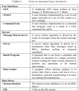
[image:8.595.168.426.276.574.2]As mentioned above, the basic types of system element used within the system were user interface programs, servers, data stores, external entities and a fairly specific set of connector types were used to link them. While these generic types of element sound fairly standard, what was interesting was the limited number of variations of them that were used in most of the system. These element types are summarised in Table I.
TABLE I. TYPES OF ARCHITECTURAL ELEMENTS
User Interfaces
- GUI A traditional GUI client written in Java Swing, C# WebForms or C++ Motif.
- WebUI A user interface implemented as a set of web pages (typically as a set of CGI scripts or a Java webapp)
- Command Line A user interface implemented as a command line program, such as a script or a Unix command line utility
Servers
- Message Driven Server A server whose operation is driven by the recipt of messages from the system message bus
- Server A server whose operation is driven by a mechanism other than messages (such as RPCs, database polling or temporal schedules)
- Batch Program A program that is run from a scheduler and performs its operation in a single execution, without waiting for other system elements to perform any operations or for human intervention.
- Data Loader A program whose primary purpose is to extract data from a source and move it to a destination, typically transforming it in some way during the transmission.
Data Stores
- System database The shared system database or a set of tables from it
9
External Entities
- Subsystem Another subsystem that communicates with this one in some way
- External System An information system outside our system that a subsystem communicates with in some way
- External Data Source A Data Source outside our system that a subsystem receives data from (such as a source of security prices)
The fairly restricted set of inter-element connectors in use throughout the system is described in Table II.
TABLE II. TYPES OF ARCHITECTURAL CONNECTORS
RPC A synchronous inter-process procedure call (usually XML over HTTP)
Direct Invocation An in-proess direct procedure invocation (calling a library)
Database Data Flow Writing data to a database table or tables to allow it to be used by another element
File Data Flow Writing data to a filesystem file to allow it to be used by another element
System Messaging Dispatch and receipt of messages over the system message bus via a named messaging destination
In order to allow for the inevitable special cases that are found in a system of this scale, an “other” type was also allowed for both components and connectors, which could be annotated using a UML style stereotype to make its type clear.
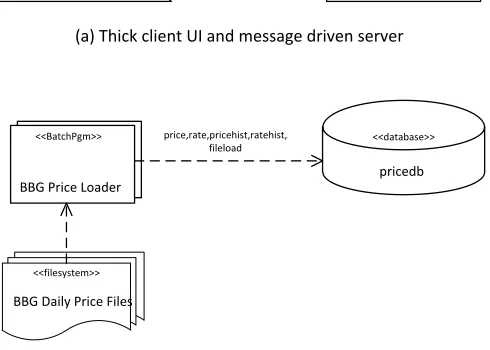
Most architectural styles limit the element and connector configurations that they allow. In this style, there weren’t really any such constraints defined formally, although there were combinations that were encouraged and discouraged (e.g. UI Clients should connect to Message Driven Servers, but not access the database). However, most configurations of element and connector types could be found somewhere in the system! A number of the common patterns were captured as examples in the notation documentation.
10
Figure 1. Examples of the ADL Notation Illustrating Preferred Configurations
The notation used to express the examples is explained more fully in the next section, but briefly triangular shapes represent user interfaces, rectangles represent server resident elements (servers, batch programs), files and databases are represented by the fairly conventional “record stack” and “drum” shapes, while connectors are represented by arrows using a variety of line types (the line type in example (a) being messaging, the line type in example (b) being stored data access).
B The Architecture Description Language
Once the universe of required element and connector types was understood, we needed a notation that would allow instances of the style (i.e. the subsystems) to be clearly represented. As explained earlier, we decided to define a custom notation because the initial discussions with the teams had made it clear that getting people to use a specific tool or invest much effort in learning the notation was going to be very difficult. This was a key reason for creating a very simple notation and “just drawing pictures” rather than trying to apply a general-purpose notation or create machine readable models.
Given people’s general enthusiasm for diagrams over text, we chose to create a graphical notation rather than a more formal textual one. We could have created an equivalent textual notation to provide an alternative concrete syntax, but we didn’t need one for this project and as we were not trying to create a reusable ADL we had no reason (or the time) to create alternative notations.
When defining the graphical detail of the notation, the advice in [27] were particularly useful, in particular the exhortation to avoid construct overload, deficit, redundancy or excess, the suggestion to systematically consider the visual variables of each shape (shape, size, colour,
<<GUI>>
Order Manager
<<Message Based Server>> Order Management
Server ORDERUIREQ(OrderUiCmd)
<<BatchPgm>>
BBG Price Loader
<<database>>
pricedb price,rate,pricehist,ratehist,
fileload
<<filesystem>> BBG Daily Price Files
(a) Thick client UI and message driven server
11
orientation, brightness and texture) and the need for deliberate selection of shapes so that their appearance suggested their meaning, to help achieve semantic transparency.
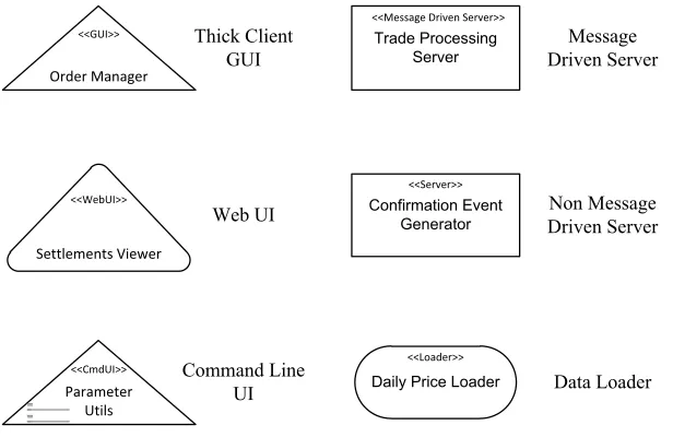
[image:11.595.106.414.208.408.2]We created the graphical notation by selecting a base shape for each major type of element (server, user interface, data store, external entity) and designing a variation of the shape for each subtype of the element. The diagrams were likely to be printed in black and white, so brightness and colour were used in a very limited way (just being used as an informal diagrammatic annotation, rather than having a predefined meaning). Each element had to have a name, shown on its symbol and optionally a stereotype (discussed below). Examples of the notation for some of the more important element types are shown in Figure 2.
Figure 2. ADL Element Types
A triangle was used as the base shape for user interfaces and a rectangle for server resident components. The triangle was chosen as it hinted at the head and shoulders shape of a user and the triangles were then modified slightly for each type of user interface (the thick client having sharp corners, the web user interface having rounded corners as it blurs the distinction between “client” and “server” and the command line utility having a graphical representation of a command line interface added to it). Similarly, a rectangle is the base shape for server elements (based on long accepted conventions) with a stereotype being used to indicate the type of server and a “lozenge” variant being used to indicate a data loader (hinting at pieces of data being transmitted through it).
An arrow of some form was used to represent all of the connector types, with the arrowhead usually indicating the direction of data flow. All connectors were defined to be one way connections, with the exception of data access connectors, which could indicate read and write activity with arrow heads at both ends of the connector if appropriate. The convention for RPC connectors was defined to be a one-way arrow from the caller to the target. No attempt was made
<<GUI>>
Order Manager
<<WebUI>>
Settlements Viewer
<<CmdUI>>
Parameter Utils
<<Message Driven Server>> Trade Processing
Server
<<Server>> Confirmation Event
Generator
<<Loader>>
Daily Price Loader
Thick Client GUI
Web UI
Command Line UI
Message Driven Server
Non Message Driven Server
12
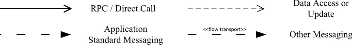
[image:12.595.82.445.181.236.2]to represent the various complicated possibilities of dependency and initiation of interaction using the connector symbols. Each connector had to indicate what was carried over the connection, with message flows being annotated with a message data type, file and database connectors being annotated with table or record names, and RPC and direct invocation connectors being annotated with the name of the service or procedure they were calling. Examples of the notation for the main connector types are shown in Figure 3.
Figure 3. ADL Connector Types
The RPC or direct procedure call is shown using a solid arrow, messaging is shown using a line with embedded dots, suggesting messages flowing over it, while data access is shown using a regular chain line, suggesting records being read or written over the connector.
A general mechanism used on elements and connectors was the stereotype, adopted from UML, where the type of an architectural element is made clear by annotating it with a type name using the convention “«type»” on the symbol concerned. This allowed the casual reader to understand the types of element on the diagram without having to understand the notation and allowed new element types to be easily introduced.
The semantics of the elements and connectors were generally based on the semantics of the corresponding element and connector implementations in the system: broadcast messaging in the system worked in a particular way, a relational database has well understood behaviour, a web service call is widely understood and a message driven server was a concept that most people understood with little further explanation. Undoubtedly there were cases where elements on diagrams had surprising behaviour because they did not behave entirely as expected given their type, but on the whole, the resulting documents were good enough to form a useful architecture description.
In order to ensure that the process produced more than just pictures, we defined a set of required attributes for each type of element and connector. Part of this task was defining enumerations of expected standard values for many of the attributes, again to standardise and simplify the process of recording the information (such as standard lists of data domains [“trading”, “counterparties”, “securities”, …], lists of programming languages in use [C++, Java, C#, Perl] and so on).
In order to simplify and standardise the subsystem descriptions, a set of wiki page templates and a comprehensive Microsoft Visio stencil were created, along with clear instructions, quick reference material and – most crucially – a fully worked example of the documentation for one subsystem. This allowed a number of conventions, such as hyperlinking element names to allow navigation through the documents, to be illustrated and encouraged by example. A hierarchy of
<<flow transport>>
RPC / Direct Call Data Access or Update
Application
13
empty wiki pages for the required subsystem descriptions was also created so that authors knew where to put their documents and so they could be unambiguously referenced.
The result of this process was a relatively informal definition of a simple ADL with a graphical notation and set of well-defined conventions for storing the supporting text needed to explain and fully define the subsystem descriptions. The ADL is tied very strongly to the particular architectural style of this system (its element and connector types) and we deliberately did not attempt to generalise the language, as this very tight link to the system to be described was one of its major strengths for our situation. In this way, our ADL is rather like the ADLs defined to support specific implementation frameworks like DAOP-ADL [29] which was developed to describe DAOP applications [30] and CBabel [31] which was developed to allow the definition of CR-RIO applications [32].
7 ACASE STUDY OF THE APPROACH IN USE
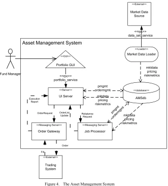
The system described in the case study is the Asset Management System (AMS) a financial asset management system used by a fund manager to support making and executing investment decisions for a large-scale investment portfolio. The example is based on a real subsystem from the case study, modified slightly in order to retain anonymity.
14
A Architectural Description
[image:14.595.139.470.117.483.2]The functional structure of the AMS is described using our system-specific ADL notation in Figure 4.
Asset Management System
<<database>> AMSdb pmgmt ordermgmt <<External>> Trading System <<Messaging Server>> Job Processor <<Server>> UI Server <<GUI>> Portfolio GUI mktdata pricing riskmetrics mktdata pricing riskmetrics OrderRequest Execution Report
Fund Manager <<rpc>>
portfolio_service
<<Loader>>
Market Data Loader
<<External>> Market Data Source <<rpc>> data_set_service <<Messaging Server>> Order Gateway pmgm t orde rmgm t mktdata pricing riskmetrics Rebalance Request OrderList Update Order Fill
Figure 4. The Asset Management System
The elements of this architectural structure are described in TABLE III.
Element Name
Type Description
Portfolio GUI
GUI The responsibilities of the Graphical User Interface (GUI) are to provide the asset managers using the system with the ability to view and analyse their portfolios, to request (and monitor progress of) long running system operations (such as order generation) and to check, enter, dispatch and monitor orders that go for execution to trading systems. The GUI provides a human interface and requires an RPC interface to the UI Server to provide it with services and data.
UI Server Messaging Server
15
AMSdb Database The system database’s responsibility is to store the portfolio, analytical, market and (system) operational data that the system requires to operate. It provides an SQL based DML interface to allow data to be inserted, manipulated or retrieved.
Job Processor Messaging
Server The responsibilities of the Job Processor are to execute long running processing items (“jobs”) such as investment analytics and automated order list generation. The processor can be configured to run particular jobs on temporal schedules and can also be requested to execute particular jobs on demand. The processor provides a message based job control and status request interface and requires an SQL query based interface to the database. Market Data
Loader
Loader The responsibility of the Market Data Loader (MDL) is to retrieve various forms of market data from an internal Market Data Source system and load the data into the database, handling versioning and business date identification as part of the loading process. The datasets required include securities prices, bond yields, interest rates, FX rates, volatilities, correlations and so on. The loader requires a data retrieval interface to the MDL system, allowing data sets to be retrieved on demand.
Order Gateway
Messaging Server
The responsibility of the Order Gateway is to accept incoming orders to buy and sell securities (including order parameters such as execution strategies and price limits), to forward these requests to a trading system for execution and then receive the execution reports (“fills”) indicating order execution and broadcast these to other interested parts of the system. The gateway provides a message based order request interface and a broadcast status interface and it requires a message based interface to allow order submission to a trading system.
TABLE III. THE ELEMENTS OF THE AMS
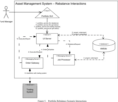
B Example Scenario – Generate Order List
16
<<Messaging Server>>
Job Processor
<<database>>
AMSdb
Asset Management System – Rebalance Interactions
2: RebalanceRequest
3: pmgmt, ordermgmt
Fund Manager
<<GUI>>
Portfolio GUI
<<Server>>
UI Server
1: portfolio_service (for rebalance) 6: portfolio_service (for get status) 7: portfolio_service (for trading request)
12: portfolio_service (for get status)
4: OrderListUpdate
<<Messaging Server>>
Order Gateway
8: ExecutionRequest
<<External>>
Trading System
9: interaction with trading system 10: ExecutionReport
[image:16.595.80.490.65.421.2]5: pmgmt, ordermgmt 10: pmgmt, ordermgmt
Figure 5. Portfolio Rebalance Scenario Interactions
The interactions between system elements necessary to implement this scenario are described in TABLE IV.
Step From To Type Connector Description
1 GUI UI Server RPC portfolio_service Fund manager selects a portfolio and instructs the system to create an order list for it. The GUI invokes an RPC indicating that the indicated portfolio should be rebalanced.
2 UI Server Job Processor
Msg Rebalance Request
The UI Server sends a request message to indicate that the portfolio should be “rebalanced”. This is routed to the Job Processor. 3 Job Processor AMSdb DB “pmgmt” &
“ordermgmt” schemas
The Job Processor receives the message and in response initiates a portfolio analysis job to identify the theoretical optimal holdings in the portfolio and generate buy and sell orders to move the portfolio to that state. Portfolio state read from “pmgmt” and order lists written to “ordermgmt”
4 Job Processor UI Server Msg OrderList Update The Job Processor sends a status message indicating that new order lists exist, which is routed to the UI Server
5 UI Server AMSdb DB “ordermgmt” and “pmgmt” schemas
The UI Server accesses the database to get the new portfolio state and associated order list state
17
7 GUI UI Server RPC portfolio_service The GUI makes an RPC call to the UI Server to indicate that the order list should be traded
8 UI Server Order Gateway
Msg Execution Request
The UI Server creates a message to request the order list to be traded (including the list of orders) which is routed to the Order Gateway 9 Order
Gateway
Trading System
- - The Order Gateway sends the orders to an external trading system and receives status updates in return as the orders are executed 10 Order
Gateway
UI Server Msg Execution Report As the Order Gateway gets execution updates, it creates execution report messages which are routed to the UI Server
11 UI Server AMSdb DB “pmgmt” & “ordermgmt” schemas
The UI Server updates the database with the status of the orders and the effect on the portfolio
12 GUI UI Server RPC portfolio_service The GUI makes RPC calls to the UI Server and gets the updated status of the orders and the changes to the portfolio in its response
TABLE IV. INTERACTION DESCRIPTIONS FOR THE PORTFOLIO REBALANCE SCENARIO
A full architectural description for a subsystem would also include a lot of operational and implementation oriented information such as links to operational instructions, links to source code control systems and automated build systems and links to test specifications and results. We do not attempt to reproduce any of that here as the majority of such information was in the form of links to other internal systems and nearly all of the information is context dependent and so not particularly meaningful outside the organisation operating the system.
8 THE EXPERIENCE GAINED
A Creating the Architecture Description
As mentioned earlier, two experienced architects led the project to create the architecture description, which included identifying the underlying architectural style, defining a clear approach, defining the ADL and leading the work to capture the architectural descriptions. There were approximately 20 development teams who owned significant subsystems that needed to be included in the scope of the project.
In order to organise the work, the development teams were ranked in order of the criticality of their subsystems in terms of how central they were to key organisational workflows and this acted as an ordered backlog of work for the architects.
The general approach taken to the task was simple and involved approaching each team and asking for a single person to be nominated as the owner of their documentation. A conference call was then held with this person and the group manager to explain the project and the approach. The team was asked to commit time and effort to completing their documents and to commit to a timeline for completing the agreed deliverables (a team often had a number of subsystems that needed to be documented and for planning purposes the creation of a subsystem description was decomposed into some standard subtasks). In return, the architects leading the effort offered training, practical assistance (such as drawing diagrams) and to review the descriptions produced.
The interactions with different teams varied greatly, with some teams producing their documentation largely unaided, needing only some review and minor correction, while others were simply incapable or unwilling to produce what was needed and the architects ended up writing most of the documentation for these teams.
18
understanding how to represent their subsystem. In general this seemed to stem from an inability to abstract away from the implementation, resulting in a confusing mix of concrete and totally abstract concepts, which they then struggled to relate to each other. None of these subsystems were very difficult to represent and in order to make progress the architects often stepped in and simply created the models.
Another interesting problem was tooling. Everyone in the organisation had access to the wiki and knew how to use it, so document authors could fill in the tables and text without any difficulty. However, not everyone had access to Microsoft Visio and even of those that did, some obviously didn't know how to use it. Again, the solution to this was simply for the architects overseeing the process to create diagrams for some subsystems. This was a useful lesson and provided further evidence that avoiding UML and more specialised modelling tools had been a good decision. In this organisation, requiring the use of UML and modelling tools would have been a significant barrier to getting architectural descriptions created.
Over time, a significant and useful body of subsystem descriptions emerged and this allowed the architects to create a summary level architecture description that showed how the subsystems related to each other. Some use of scripting to process the wiki subsystem descriptions and drawing tool macros to generate parts of the summary level diagrams allowed some degree of automation, although it was still a fairly manual process.
The process of capturing the architecture description took about six months, with the architects working on it approximately 60% of their time and the development teams working on it as their project schedules allowed.
B The Results of the Project
The outputs of the project were as follows.
• A fairly consistent architecture description for most of the system that provided an accurate
and largely complete view of its subsystems, their components and their dependencies. Each subsystem was described using a standardised approach, which captured the same information for each one and presented it in a consistent manner through the use of the templates provided. This made the information provided easy to navigate and check for completeness.
• An informal definition of the architectural style used across most of the system and the
typical patterns used when implementing it.
• A degree of visibility and understanding of the structure, scale and interconnectedness of
the system which hadn't been achieved before. The consistent presentation of system design information in a single location allowed the overall system structure to be more easily understood compared to the previous inconsistent descriptions on scattered wikis and web sites. This appeared to allow a number of senior technical managers to achieve new insights into the system.
19
and continued its use and maintenance (primarily to support production operation of the system, a use which was not foreseen at the outset of the project).
C Evaluating the Usefulness of the ADL
Early practical experience led to some rapid refinement of the notation to remove ambiguities that had not been apparent to its creators, and to introduce some missing concepts. However, after three or four teams had used the approach over a period of about 6 weeks, the ADL itself remained stable for the rest of the project.
As the project neared completion we started to validate what was being produced with some of the important stakeholders, particularly the senior technical managers in the organisation. To do this we met with them and demonstrated what was being produced and what the completed architectural description would contain, discussing possible uses of it (such as impact analysis, pre-implementation reviews, incident post-mortems and regulatory enquiries). We were pleased to find that this stakeholder group reacted positively to what they were shown, with responses ranging from fairly neutral (where the possible usefulness was acknowledged but no specific use of it particularly interested them) to very positive (where they wanted to start using it immediately). Given this informal but consistently positive sentiment, we felt that our notation and approach had been validated (an outcome which was anything but certain at the start of the project, when the use of a specific notation and a highly prescriptive form for the documentation had been viewed as very risky).
A factor that was constant throughout the project was that teams who had the ability to identify clear abstractions for their subsystems also appeared to find the ADL helpful and straightforward to use, as the ADL gave them a clearly defined way to represent their models and they didn’t have any difficulty in representing their models using it. These teams tended to create their models with little or no assistance once they’d asked a few clarifying questions about the purpose of the models and the semantics of the notation.
In contrast, teams who struggled to identify good abstractions never really grasped how to use the ADL and needed constant assistance, to the point of needing to have parts of their architectural descriptions completely rewritten for them. What was interesting about this stark contrast in modelling ability was that we could find no obvious factor to explain it in terms of educational background, age, team size, technology preferences, type of subsystem, geographical location or any other relevant factor. We did observe that even in teams that produced good models, the ability and enthusiasm to do this varied and even for large subsystems we found that it tended to be one or two people in a team who did all of the modelling on behalf of the rest of the team. We don’t know whether there were many other people in those teams who would have done an equally good job, but based on hallway conversations, we suspect not. Our conclusion was that relatively few people in the general population of software engineers we worked with find modelling straightforward, but we were not sure why this was the case.
20
that the straightforward and prescriptive nature of the approach would guide people to create useful models, even if they did not find modelling easy, and it was a disappointment that the approach failed to achieve this.
Looking back to the success criteria we had set ourselves at the start of the project, we considered whether the architectural description we had created was useful for our three goals to create a catalogue of what was there, to allow impact analysis and to facilitate communication (see Section 4).
• Create a Catalogue of the Current State – the project created the first comprehensive
description of the system and so provided a very useful descriptive catalogue of the current state of the architecture. The weakness of the architectural description as a catalogue was that it was only as comprehensive as the authors of each piece decided to make it. However, it was possible to cross check it against a number of systems that were known to contain complete lists of the elements in the production system (as they were used for automated tasks relating to deployment). Sampling about 30% of the architectural description and cross checking this against the lists of deployment elements revealed a high degree of completeness, so confidence in its use as a catalogue was high.
• Allow Impact Analysis – the architectural description quickly proved its worth for impact
analysis and helped considerably with the process of understanding the impact of proposed changes. This was primarily due to the fact that it allowed the interconnectedness of system elements to be quickly assessed, information that hadn’t been easy to find before.
• Communicate – the architectural description was quickly recognised to be a comprehensive
knowledge base of the system’s design information and so helped inter-team communication (when people in one team could use it to understand another team’s subsystem). It also acted as a single place where further information could be gathered. As mentioned earlier, the architects involved in creating the architectural description moved onto other work soon after its initial creation, however it does appear to have continued to be used, to grow and to evolve, suggesting that it did fulfil this role.
Based on this fairly informal assessment, we judged the project to have met the goals we set for ourselves and the architectural description became a useful resource within the organisation, as a centralised and standardised source of design information for the system.
9 LESSONS LEARNED FROM THE PROJECT
At the start of the project, no one involved in it had much experience in using ADLs in an industrial context. The experience the architects had between them was limited to some simple use of ADLs in an academic context and some significant experience of using UML for architectural modelling in large industrial projects. Therefore, we had relatively few preconceptions as to how successful the project would be and on the whole we were pleased with its results.
The main lessons that were learned during the course of the project were:
• A specialised ADL can have benefits over a general modelling language like UML and
even a simple ADL can be used to create useful results.
• The more specialised an ADL is, and so the closer it matches the implementation style of
21
this sounds like an obvious point, it is contrary to the conventional industrial approach of using a general modelling language like UML or SysML and also contrasts with the domain independent nature of most academically developed ADLs.
• Carefully designing the detail of the graphical notation pays off. Using shapes that hint at
their meaning and using a range of graphical dimensions to differentiate shapes helps people to remember them, even if they don’t guess the link between the shape and the concept themselves. Again, this is not reflected in mainstream notations like UML or most existing ADLs, where little effort is made to identify meaningful symbols for concepts.
• Consistency in the notation is very important and having a base shape for a general concept
with refinements to it for different sub-concepts appears to help people considerably when interpreting the diagrams.
• Providing high quality support materials including an example based description of the
approach and notation, a number of realistic completed examples and a set of templates for new documents is very important. We found repeatedly that people are much better at “filling in the gaps” rather than following a set of instructions and creating something from scratch.
• Utilising familiar tools helps with the acceptance of the approach. In this particular
organisation, there were no complaints or difficulties with the use of a wiki for the text and tables information, whereas a very widely used commercial drawing tool (Visio) caused problems, even with a carefully tailored template, because it was not widely used in the organisation already.
These lessons aren’t all that surprising but the importance of what seemed to be quite minor things (such as worked examples and quick reference cards) is important and is useful to bear in mind for the future. The importance of matching the ADL to the specific domain being modelled is also a lesson that is not reflected in most modelling languages today, which tend towards the general rather than the specific.
Given the relative success of this project, it is natural to ask how generally applicable its results are and how repeatable it is likely to be. Given what we learned during the project, particularly the fact that the specialised nature of the notation was a key factor in its success, we feel that these lessons may well have general applicability, but only in the broad sense. People like to be guided and they like familiar tools and techniques. However the specific tools or techniques that work will be specific to each environment and people in different environments will have different levels of enthusiasm for learning new approaches. However, when trying to get a significant amount of work done by people who are agnostic to the approach, familiarity and accessibility appear to help greatly with acceptance.
22 10 SUMMARY AND CONCLUSIONS
An organisation in the financial services industry wanted to create an architecture description for a large existing enterprise system. In order to achieve this within acceptable cultural and time constraints a simple, custom architecture description language was defined in order to make the process of capturing the architecture description as simple and prescriptive as possible.
While it was not clear at the outset whether this approach would be successful, the ADL actually proved to be a helpful and effective tool for capturing this specific architecture description in an entirely industrial context. A large architecture description was created, something that the organisation had not achieved before, and this allowed new perspectives on the system to be gained.
What the approach did not achieve was helping those who found modelling difficult to create effective models. People who found abstraction difficult seemed to find it just as difficult when using this very specific approach as when using a general-purpose notation, which was a surprise and a disappointment.
Having said that, the factor that appeared to make the approach generally successful was focusing on describing the specific structures in the system of interest, rather than trying to create a general-purpose approach, which would be effective for other uses too. Other factors which contributed to the success of the approach were its simplicity (which traded sophistication for accessibility), a carefully designed, consistent graphical notation, the availability of a large amount of tutorial and reference material to guide document authors, and the use of very familiar tools, which users of the notation were already familiar with.
REFERENCES
[1] D. Di Ruscio, I. Malavolta, H. Muccini, P. Pelliccione, and A. Pierantonio, "ByADL: an MDE framework for building extensible architecture description languages," in
Proceedings of the 4th European Conference on Software Architecture, Copenhagen, Denmark, 2010, pp. 527-531.
[2] P. Cuenot, P. Frey, R. Johansson, H. Lonn, Y. Papadopoulos, M.-O. Reiser, et al., "The EAST-ADL architecture description language for automotive embedded software," in
Proceedings of the 2007 International Dagstuhl conference on Model-based engineering of embedded real-time systems, Dagstuhl Castle, Germany, 2010, pp. 297-307.
[3] F. Oquendo, "π-ADL: an Architecture Description Language based on the higher-order typed π-calculus for specifying dynamic and mobile software architectures," ACM SIGSOFT Software Engineering Notes, vol. 29, pp. 1-14, 2004.
[4] R. Bashroush, I. Spence, P. Kilpatrick, and T. Brown, "Towards More Flexible Architecture Description Languages for Industrial Applications," in EWSA 2006. vol. 4344, V. Gruhn and F. Oquendo, Eds., ed Nantes, France: Springer-Verlag, 2006, pp. 212-219.
23
[6] R. van Ommering, F. van der Linden, J. Kramer, and J. Magee, "The Koala component model for consumer electronics software," IEEE Computer, vol. 33, pp. 78-85, 2000. [7] R. Allen, S. Vestal, D. Cornhill, and B. Lewis, "Using an architecture description
language for quantitative analysis of real-time systems," in Proceedings of the 3rd international workshop on Software and performance, Rome, Italy, 2002, pp. 203-210. [8] P. Feiler, B. Lewis, and S. Vestal, "Improving Predictability in Embedded Real-Time
Systems," Software Engineering Institute, Carnegie Mellon University, Pittsburgh, Pennsylvania2000.
[9] H. Lonn, T. Saxena, M. Torngren, and M. Nolin, "Far east: Modeling an automotive software architecture using the east adl," 2004.
[10] N. Medvidovic and R. N. Taylor, "A classification and comparison framework for software architecture description languages," IEEE Transactions on Software Engineering, vol. 26, pp. 70-93, 2000.
[11] P. C. Clements, "A Survey of Architecture Description Languages," in Proceedings of the 8th International Workshop on Software Specification and Design, 1996, p. 16.
[12] "Standard AS5506/1: SAE Architecture Analysis and Design Language (AADL)," ed: SAE International, 2006.
[13] D. Garlan, R. T. Monroe, and D. Wile, "Acme: architectural description of component-based systems," in Foundations of component-based systems, T. L. Gary and S. Murali, Eds., ed: Cambridge University Press, 2000, pp. 47-67.
[14] K. Dunsire, T. O'Neill, M. Denford, and J. Leaney, "The ABACUS Architectural Approach to Computer-Based System and Enterprise Evolution," in Proceedings of the 12th IEEE International Conference and Workshops on Engineering of Computer-Based Systems, 2005, pp. 62-69.
[15] R. Allen, "A Formal Approach to Software Architecture," PhD thesis, Computer Science, CMU, Pittsburgh, 1997.
[16] M. Shaw, R. DeLine, and G. Zelesnik, "Abstractions and implementations for architectural connections," in Proceedings of the 3rd International Conference on Configurable Distributed Systems, Annapolis, Maryland, 1996, pp. 2-10.
[17] R. Allen and D. Garlan, "The Wright Architectural Specification Language," Carnegie Mellon University, Software Engineering Institute, Pittsburgh, PA1996.
[18] D. Batory and B. J. Geraci, "Composition Validation and Subjectivity in GenVoca Generators," IEEE Transactions on Software Engineering, vol. 23, pp. 67-82, 1997. [19] D. C. Luckham, J. J. Kenney, L. M. Augustin, J. Vera, D. Bryan, and W. Mann,
"Specification and analysis of system architecture using Rapide," IEEE Transactions on Software Engineering, vol. 21, pp. 336-354, 1995.
[20] M. Moriconi and R. A. Riemenschneider, "Introduction to SADL 1.0: A Language for Specifying Software Architecture Hierarchies," SRI International,1997.
24
[22] R. Bashroush, T. J. Brown, I. Spence, and P. Kilpatrick, "ADLARS: An Architecture Description Language for Software Product Lines," in Proceedings of the 29th NASA/IEEE Software Engineering Workshop (SEW'29), Greenbelt, MD, 2005, pp. 163-173.
[23] R. Bashroush, I. Spence, P. Kilpatrick, T. Brown, W. Gilani, and M. Fritzsche, "ALI: An Extensible Architecture Description Language for Industrial Applications," in
Proceedings of the 15th IEEE International Conference on Engineering of Computer-Based Systems (ECBS), Belfast, UK, 2008, pp. 297-304.
[24] R. Bashroush and I. Spence, "An Extensible ADL for Service-Oriented Architectures," in
Information Systems Development - Towards a Service-Provision Society, G. A. Papadopoulos, W. Wojtkowski, W. G. Wojtkowski, S. Wrycza, and J. Zupancic, Eds., ed New York: Springer, 2009, pp. 227-237.
[25] M. M. Lankhorst, H. A. Proper, and H. Jonkers, "The Architecture of the ArchiMate Language," in Proceedings of the 10th International Workshop on Enterprise,
Business-Process and Information Systems Modeling (BPMDS 2009) held at CAiSE, Amsterdam,
Netherlands, 2009, pp. 367-380.
[26] K. Smolander, K. Lyytinen, V.-P. Tahvanainen, and P. Marttiin, "MetaEdit: a flexible graphical environment for methodology modelling," in Proceedings of the 3rd International Conference on Advanced Information Systems Engineering, Trondheim, Norway, 1991, pp. 168-193.
[27] D. Moody, "The "Physics" of Notations: Toward a Scientific Basis for Constructing Visual Notations in Software Engineering," IEEE Transactions on Software Engineering,
vol. 35, pp. 756-779, 2009.
[28] M. Shaw and D. Garlan, Software architecture: perspectives on an emerging discipline
vol. 1: Prentice Hall Englewood Cliffs, 1996.
[29] M. Pinto, L. Fuentes, and J.-M. Troya, "DAOP-ADL : An Architecture Description Language for Dynamic Component and Aspect-Based Development," in 2nd international conference on Generative programming and component engineering (GPCE '03), Erfurt, Germany, 2003, pp. 118-137.
[30] M. Pinto, L. Fuentes, and J. M. Troya, "Towards an aspect-oriented framework in the design of collaborative virtual environments," in Distributed Computing Systems, 2001. FTDCS 2001. Proceedings. The Eighth IEEE Workshop on Future Trends of, 2001, pp. 9-15.
[31] C. Braga and A. Sztajnberg, "Towards a Rewriting Semantics for a Software Architecture Description Language," Electronic Notes in Theoretical Computer Science, vol. 95, pp. 149-168, 2004.