ISSN Online: 2161-4725 ISSN Print: 2161-4717
Special Relativity in Three-Dimensional
Space-Time Frames
Tower Chen
1, Zeon Chen
21Retiree from Unit of Mathematical Sciences, College of Natural and Applied Sciences, University of Guam, UOG Station, Mangilao,
Guam, USA
2Independent Researcher, Berkeley, California, USA
Abstract
In Newton’s classical physics, space and time are treated as absolute quantities. Space and time are treated as independent quantities and can be discussed separately. With his theory of relativity, Einstein proved that space and time are dependent and must be treated inseparably. Minkowski adopted a four-dimensional space-time frame and indirectly revealed the dependency of space and time by adding a constraint for an event interval. Since space and time are inseparable, a three-dimensional space-time frame can be constructed by embedding time into space to directly show the inter-dependency of space and time. The formula for time dilation, length contraction, and the Lorenz transformation can be derived from graphs utilizing this new frame. The proposed three-dimensional space-time frame is an alternate frame that can be used to describe motions of objects, and it may improve teaching and learning Special Re-lativity and provide additional insights into space and time.
Keywords
Four-Dimensional Space-Time Frame, Three-Dimensional Space-Time, Time Contraction, Length Contraction, Lorenz Transformation, Big Bang, Multiple Big Bangs, Quantum Entanglement
1. Introduction
In order to describe the position of a static object, Descartes constructed three axes perpendicular to one another in the space using
(
x y z, ,)
coordinate to represent the position of this static object along x-axis, y-axis, and z-axis. The coordinate is called Cartesian frame.In order to describe the position of a moving object, Galileo constructed an time axis How to cite this paper: Chen, T. and
Chen, Z. (2016) Special Relativity in Three- Dimensional Space-Time Frames. Interna-tional Journal of Astronomy and Astro-physics, 6, 410-424.
http://dx.doi.org/10.4236/ijaa.2016.64033
Received: November 5, 2016 Accepted: December 13, 2016 Published: December 16, 2016
Copyright © 2016 by authors and Scientific Research Publishing Inc. This work is licensed under the Creative Commons Attribution International License (CC BY 4.0).
which is perpendicular to three axes in the space, which using
( )
x t, ,( )
y t, , and( )
z t, coordinate to represent the position of this moving object along x-axis, y-axis, and z-axis. Galileo combined these coordinates into the(
x y z t, , ,)
coordinate. This coordinate is called Galileo’s frame.In order to describe the position of a moving object in Special Relativity, Minkowski constructed a time axis, ct, which is perpendicular to three axes in the space simul-taneously. First, he treated space and time independently, then added a constraint:
( )
22 2 2
const.
x +y +z − ct = in order to make space and time dependent. He used the
(
ct x y z, , ,)
coordinate to represent the position of this moving object along x-axis,y-axis, and z-axis. This coordinate is called Minkowski’s frame.
In order to describe the position of a moving object in Special Relativity, we con-struct polar coordinate for time on x−y plane, y−z plane, and z−x plane, be-cause space and time are dependent. We use the
(
x−ct y, , −ct z−ct)
coordinate to represent the position of this moving object along x-axis, y-axis, and z-axis. The unit for the radius of polar coordinate is light-sec or period T, the unit for x-axis, y-axis, andz-axis in space is light-sec or wavelength, λ. We embed time into space directly by the velocity of light, c, which is equal to λ T . It shows that space and time are dependent. This coordinate is called 3-d s-t frame.
Theory of one Big Bang creating the universe is based on 4-d s-t frame. There are many unsolved paradoxes in this theory: Hubble’s constant should be a fixed value, but having wide range; There are two different methods to measure the distance of a qua-sar, but results are very different; In order to raise up the density of the universe keep-ing present status, there is need of dark matter; In order to explain the observation of acceleration of the universe, there is need of dark energy. The paper of “The Shell Mod-el of the Universe: a universe generated from multiple big bangs” [1], which is based 3-d s-tframe, was published in Research on Gravitation, Astrophysics and Cosmology Journal of Modern Physics in July 2016. This paper solves the problems raised from the standard model of the universe generated from Big Bang based on 4-d s-t frame.
Any particle’s motion in space can be described by choosing a 3-d s-t frame with the proper velocity of a medium [2]. In Special Relativity, time dilation and length contrac-tion can be geometrically derived using two 3-d s-t inertial frames having a constant relative velocity by choosing the velocity of light as a medium. In addition, the Lorentz transformation can also be straightforwardly obtained from the result of time dilation and length contraction in 3-d s-t frames.
the probability of uncertainty in measuring a quantum with the unit of length. The second beam of photon may hit a different spot fromthe first one because of the rota-tion of the particle. To verify the assumprota-tions made previously, the Heisenberg un-certainty relationship can be derived by multiplying these two independent probabili-ties (matter wavelength of an object and light wavelength of measuring medium) [3].
For quantum entanglement, there is a medium affecting each of a pair of particles with a velocity much faster than light, and it might be with an infinity velocity. It is against the main assumption of Special Relativity: the velocity of light is the upper limit of particle in the universe. If we locate a particle on the platform and the other particle at any distance from the platform, then the medium can be treated as the moving train. If the moving train travels with the velocity of light, the observers on the train will reach the other particle at any distance from the platform with zero second. It means that the medium will affect both particles instantly and the distance between both par-ticles is also zero meter measured by observers. It can apply to any force between two objects including gravitational force, as long as the medium between two objects trav-eling with velocity of light. The proposed 3-d s-t frame shows the advantage of 3-d s-t frame [4].
2. Construction of a 3-d s-t Frame
The motion of any particle in space can be decomposed into its x, y, and z directions. In order to describe the motion of an object in 3-dimensional space along the locations of
x-axis, y-axis, and z-axis, we can construct a new space-time frame. Spheres with dif-ferent radius representing difdif-ferent outgoing time, polar coordinates will be formed from circles of intersections between spheres and x-y plane, y-z plane, and z-x plane
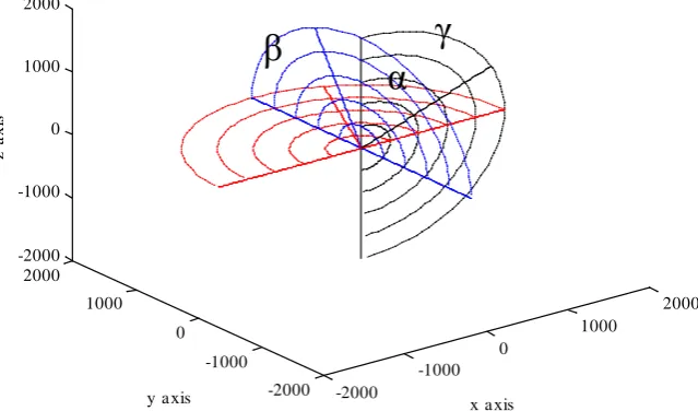
[4]. We are able to use the red polar coordinates of x-y plane, the blue polar coordinates of y-z plane, and the gray polar coordinates of z-x plane to describe the locations of a moving object moving along x-axis, y-axis, and z-axis. The construction of a 3-d s-t frame is shown in Figure 1. This kind of new coordinate frame embedding time axis into space axes is called three-dimensional space-time frame which saves one dimension. We won’t be puzzled by being not able to visualize four-dimensional space-time frame.
Its component along the x-axis can be described as a function of time, which is represented by the time circles created from the intersections between the x-y plane and the concentric time spheres. If the velocity of an appropriate medium is Vm, then the
radius of the sphere is r t
( )
=V tm at time t. The point with the properties,( )
(
)
2( )
2( )
h x t = r t −x t and cosα=x t
( ) ( )
r t , on the x-y plane can represent the location of the particle moving along the x-axis at time t. The component of motion along the y-axis can similarly be described as a function of time, which is represented by the time circles created from the intersection between the y-z plane and the concen-tric time spheres. The point with the properties,(
( )
)
2( )
2( )
h y t = r t −y t and
( ) ( )
Figure 1. The construction of a 3-d s-t frame. h(x(t)) = (r2 − x2)1/2 and cosα = x/r on the x-y plane
represent the location of the particle along the x-axis. h(y(t)) = (r2 − y2)1/2 and cosα = y/r on the y-z
plane represent the location of the particle along the y-axis. h(z(t)) = (r2 − z2)1/2 and cosα = z/r on
the z-x plane represent the location of the particle along the z-axis.
intersection between the z-x plane and the concentric time spheres The point with the properties, h z t
(
( )
)
= r2( )
t −z2( )
t and( ) ( )
cosγ =z t r t , on the z-x plane can repre- sent the location of the particle moving along the z-axis at time t.
If messages are relayed by sound of Vm = 350 m/sec then the radius of the sphere representing one second is equivalent to (Vm)(1 sec) = 350 m; the radius of the sphere representing two seconds is equivalent to (Vm)(2 sec) = 700 m; …; and the radius of the sphere representing n seconds is equivalent to (Vm)(n sec) = n(350) m.
If the message is transmitted by light of Vm ~3(108) m/sec, then the radius of the
sphere representing one second is equivalent to (Vm)(1 sec) = 3(108) m; the radius of
the sphere representing two second is equivalent to (Vm)(2 sec) = 6(108) m; …; and the
radius of the sphere representing n seconds is equivalent to (Vm)(n sec) = 3n(108) m.
Since the velocity of light is the limiting velocity, all possible motions of a particle can be described using this 3-d s-t frame.
In cosmology, the expansion velocity of the universe is very high, as the recession velocities of some galaxies away from the earth are nearly 90% of the velocity of light
[1]. Because all galaxies are far away from us, the interval of 1 sec would be too small to meaningfully describe their motion. The unit of time can be scaled up by choosing the light year. Hence, the radius of the sphere representing one year is equivalent to (Vm)(1 year) = 9.46(1015) m = 1ly; the radius of the sphere representing two years is equivalent
to (Vm)(2 year) = 1.89(1016) m = 2ly; …; and the radius of the sphere representing n
years is equivalent to (Vm)(n year) = 9.46n(1015) m = nly.
In high energy physics, if a particle’s velocity approaches the velocity of light, the in-terval of 1 sec would be too large to meaningfully describe its motion. The units can be scaled down by choosing the period
( )
T of any selected frequency of light as the unit of time and its corresponding wavelength( )
l as the unit of length of the space axes,-2000
-1000 0
1000
2000
-2000 -1000 0 1000 2000 -2000 -1000 0 1000 2000
x a xis y a xis
z
a
x
is
α
[image:4.595.215.535.73.261.2]because the ratio of the wavelength and wave period is equal to the velocity of light [5]. The radius of the time sphere representing 1T is chosen to equal λ
(
V tm =( )( )
c 1T =λ)
; the radius of a sphere representing 2T is chosen to equal 2λ(
V tm =( )( )
c 2T =2λ)
;; and the radius of the sphere representing nT is chosen to equal( )
(
m ( ))
nλ V t= c nT =nλ . The period of an event measured in units of time is equal to t T
τ = ; and the coordinates of a particle’s location measured in units of length are equal to wx =xλ, wy =y λ, and wz =z λ. With this transformation for particles
moving velocity closed to the velocity of light and the time interval of traveling being small, the coordinates
(
x y z t, , ,)
with sec and m as units in a 4-d s-t frame can be converted to the coordinate(
w w wx, y, z,τ)
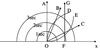
with T and λ selected asunits in this 3-d s-t frame [6].The proposed new coordinate frame can also be used to describe the motion of the object moving along the x-axis in various trajectories and at different speeds using the methods described above. In Figure 2, OA represents an object remaining stationary at O; OB represents an object moving with a relatively slow, constant velocity; OC represents an object moving with a relatively fast, constant velocity; OD represents an object mov-ing with a constant acceleration; OE represents an object movmov-ing with a constant dece-leration; and FG represents an object remaining stationary at F.
A 3-d s-t frame, created by embedding time into space directly, reveals the depen-dency of space and time. Although the space coordinates are bi-directional, time cannot be given a negative value thus, because it only has one outgoing direction in this 3-d s-t frame.
3. Time Dilation and Length Contraction
Before describing time dilation and length contraction, we will first define some terms. If two frames have a constant relative velocity between them, two frames are called a pair of inertial frames which are inertial to each other [7]. For this discussion, we will have a train passing by a station platform at constant velocity. Theoretically, we are al-lowed to choose any one frame of the two frames to be the stationary (inertial) frame and the other frame to be the moving (inertial) frame. For convenience, we construct a stationary frame S on the platform and a moving frame S’on the train.
[image:5.595.288.465.579.666.2]In Figure 3, a rod is laid along the side of the station platform. There is an observer on the platform and another observer on the train and both measure the rod’s length
Figure 2. The object stays still at O by OA and at F by FG, moves with a constant slow velocity by OB, a constant fast velocity by OC, a constant acceleration by OD, a constant deceleration by OE along x-axis.
O A
B
C D
E
F G
x
1sec 2sec 3sec
O A
B
C D
E
F G
x
Figure 3. A stationary rod is measured by a moving train. It is laid along the side of the platform.
using a sensor attached to the front of the train, i.e. the origin O’of the moving frame
S’. The length of the rod as measured by an observer in the stationary frame S, is de-fined as proper length, l0, while the length of the rod as measured by an observer in the moving frame S’, is defined as regular length, l′. When the sensor touches the left edge of the rod, the time is recorded as 0 for both observers. When the sensor touches the right edge of the rod, the time is recorded t for the observer in the stationary frame
S and t0′ for the observer in the moving frame S’. The event where the sensor moves from one end of the rod to the other can be described by the two different observers. This event occurs at the same location for the observer in the moving frame S’, then the period of the event as measured by this observer is defined as the proper time, t0′. This event happens at different locations for the observer in the stationary frame S, then the period of the event measured by this observer is defined as the regular time, t. The proper length of the rod is calculated by multiplying the train’s velocity by regular time,
0
l =vt, and regular length is calculated by multiplying the train’s velocity by proper time, l′=vt0′.
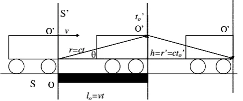
At the same time the sensor touches the left end of the rod, the observer in the mov-ing frame S’ sends a pulse of light towards the ceiling of the car, where a mirror is placed. To the observer in the moving frame S’, the light travels vertically up towards the ceiling and is then reflected vertically down. The ceiling height of the boxcar is ad-justable, such that the pulse of light reaches the ceiling at the same time that the sensor reaches the right end of the rod. In Figure 4, if it takes the time t0′ for light to reach the ceiling then the height of ceiling is equal to the distance traveled by light is
0
h= =r′ ct′, as measured by the observer in the moving frame O’. To the observer in the stationary frame O, the light travels diagonally upwards to the ceiling and is then reflected diagonally downwards. If it takes the time t for light to reach the ceiling then the distance traveled by light on each diagonal leg is r=ct,as measured by the ob-server in the stationary frame O, where
( )
2( )
2( ) ( )
2 22 2 2 2
0 .
r= l +h = vt +h = vt +r′ = vt + ct′ (1) From Figure 4, we can derived the following property for θ, where
( ) ( )
2 2( )
22 2
sinθ =h r= r −l r= ct − vt ct= 1− v c . (2)
From the previous discussion, we know that r=ct and O’
O
O’
lo=vt
to’
t l=vto’
O’
O
O’
lo=vt
to’
t l=vto’
S’ v
Figure 4. The height of the ceiling is adjustable. The pulse of light reaches the ceiling at the same time as the sensor touches the right side of the rod.
0 0
sinθ =h r=r r′ =ct′ ct=t t′ ; therefore, t≥t0′. This equation shows that the regular time, t, is larger than or equal to the proper time, t0′. This result says that the time in-terval measured by the observer in the stationary frame is longer than that measured by the observer in the moving frame. This difference is referred to as time dilation. Since
0 0 0
sinθ =t t′ =vt vt′ =l l′ , then l′ ≤l0. This equation shows that the regular length, l′, is less than or equal to the proper length, l0. This result says that the length of a rod measured by the observer in the moving frame is shorter than that measured by the observer in the stationary frame. This difference is referred to as length contraction [8].
4. Geometric Lines Representing Time Dilation and Length
Contraction
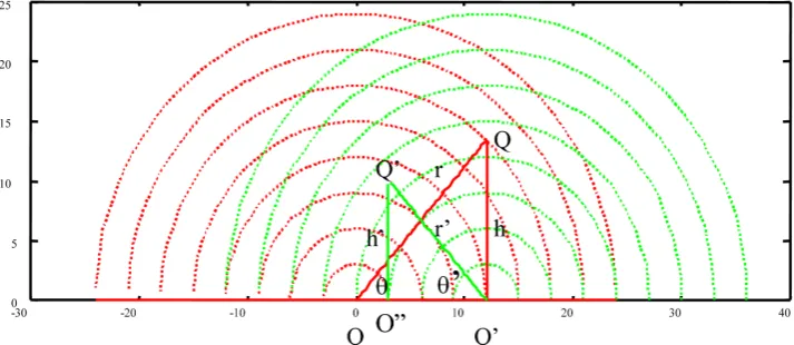
When an observer on the train moves to the right with velocity v with respect to an observer on the platform, a moving 3-d s-t frame can be constructed on the train with the observer at the origin O’ of the frame S’ and a stationary 3-d s-t frame can be con-structed on the platform the observer at the origin O of the frame S. The location of the observer at O’ on the train as described by the observer at O is OQ as shown in Figure 5, while the location of the observer at O as described by the observer at O’ is O’Q as shown in Figure 5.
The two equations,
( ) ( )
2 2( )
2sinθ =h r= ct − vt ct= 1− v c (3) and
( ) ( )
2 2( )
2sinθ ′=h r′ ′= ct′ − vt′ ct′= 1− v c (4) are derived from Figure 5, which imply that
θ θ
= ′. It also shows that sincesinθ=sinθ ′=h r=r r′ =ct ct′ =t t′ , t≥t′. (5) The event where the sensor attached to the observer on the train moves from the left of the rod to the right of the rod can be described by two the different observers. To the observer at the origin of the moving frame S’, the event occurred at the same location, and the durationof the event is called the proper time, t0′ equal to t′, which is pro-portional to the length of r′
(
r′=ct′=ct0′=h)
in Figure 5. To the observer at theO’
O
O’
lo=vt
to’
h=r’=cto’
O’
v
r=ct
O’
O
O’
lo=vt
to’
h=r’=cto’
O’
v
r=ct
θ S’
origin of the stationary frame S, the event occurred at different locations, and the pe-riod of the event is called the regular time t,which is proportional to the length of r (r =
ct) in Figure 5. Since t≥t0′, this difference is referred to as time dilation.
[image:8.595.196.553.331.486.2]Since sinθ =t t′ =vt vt′ =l l′ 0, then l′ ≤l0. The length of a rod as measured from an observer in the stationary frame O is called the proper length, l0, which is equal to OO′ =vt in Figure 5. However, the length of the same rod as measured by an observer in the moving frame S’ is called the regular length, l′,which is equal to OO′′=vt0′ in
Figure 5. Since l′ ≤l0, this phenomenon is called length contraction.
5. Lorentz Transformation
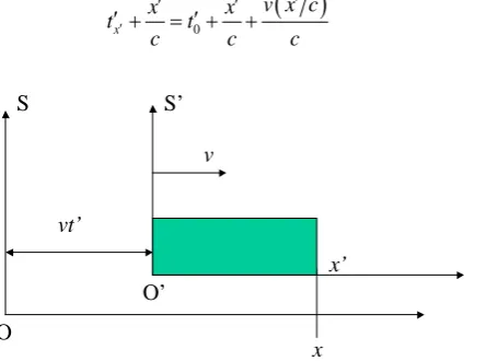
In the next discussion, we designate the occurrence of an event at the coordinate x on the x-axis of a stationary frame S, by laying a rod on the x-axis from 0 to x. The proper length l0 of the rod is equal to x measured by an observer at the origin of the statio-nary frame S. In Figure 6, the moving frame S’ moves to the right of the stationary frame S with a velocity v, and the time is set to 0 secwhen O’, passed O. The regular length of the rod as measured by the observer at the origin of the moving frame S’ is
Figure 5. The geometric meaning of time dilation and the length contraction. The origin O’ moves to the right with the velocity v with respect to the origin O. l = l0 = OO’ = vt, l' = OO” = vt' =
0
vt′ and r = ct, r' = ct' = ct0′ = h.
Figure 6. If the event happens in the coordinate x on the
x-axis on the stationary frame S, then we can assume there is a rod laid on the x-axis from 0 to x.
x x’
O
O’ v
vt’
[image:8.595.266.481.545.670.2]
equal to
( )
2 1x − v c due to length contraction, thus the relationship between these two coordinates is
( )
2 1x − v c =vt′+x′ (6) In order to check that the time tx′′ on the clock at the coordinate x' on the x'-axis is
or not synchronized with the time t0′ on the clock at the origin of the moving frame S' with the velocity v, we can designate there is a box laid on the x'-axis from 0 to x'. 1) to observers in the moving frame S’: When the light is emitted from the wall at 0 to the wall at x', the time t0′ is recorded on the clock on the wall at 0 and time tx′′ is recorded
on the clock on the wall at x'. When the light reaches the wall at x', the time 0 x t
c ′ ′ +
should be recorded on the clock on the wall at 0 and time x
x t
c
′
′
′ + should be recorded
on the clock on the wall at x', because it takes x c ′
for light to travel for the observers at
both walls on the moving frame S’. In the moving frame S’, if
0
x
x x
t t
c c
′
′ ′
′ + = +′ (7)
[image:9.595.190.556.327.672.2] [image:9.595.268.491.502.667.2]then the time tx′ on the clock on the wall at x' is synchronized with the time t0′ on the clock on the wall at 0 by letting tx′′=t0′. 2) to observers in the stationary frame S: In
Figure 7, when the light is emitted from the wall at 0 to the wall at x', he sees that the time t0′ is recorded on the clock on the wall at 0 and time tx′′ is recorded on the clock
on the wall at x'. When the light reaches the wall at x', the time 0
(
)
v x c xt
c c
′ ′
′ + + should
be theoretically recorded on the clock on the wall at 0 because it takes extra time
(
)
v x c c
′
for light to travel the extra distance v x c′ ′
(
)
but time tx x c′
′
′ + is actually
recorded on the clock on the wall at x'. To observers in the stationary frame S, if
(
)
0
x
v x c
x x
t t
c c c
′
′
′ ′
′ + = +′ + (8)
Figure 7. If the event happens in the coordinate x' on the
x'-axis on the moving frame S’, then we can assume there is a box laid on the x'-axis from 0 to x'.
x x’
O
O’ v
vt’
then the time tx′ on the clock on the wall at x' is synchronized with the time t0′ on the clock on the wall at 0 by letting
(
)
0
x
v x c
t t
c
′
′
′ = +′ (9)
in the moving frame S’. This means that the proper time is adjusted by t v x c
(
)
c′
′ + at
the coordinate x' when the proper time is t′=t0′ at the coordinate 0 in the moving frame S’. The regular time t measured by observers in the stationary frame S is adjusted by
(
)
( )
21 v x c
t v c
c ′
′ + −
due to time dilation, thus the relationship between these two coordinates is
(
)
( )
21 v x c
t t v c
c ′
′
= + −
(10) Combining all relationships between coordinates of the stationary frame S and the moving frame S’ forms the following Lorentz transformation:
( )
2 1x − v c =vt′+x′ (11)
y= y′ (12) z=z′ (13)
(
)
( )
21 v x c
t t v c
c ′
′
= + −
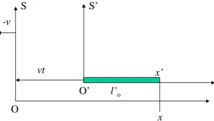
(14) In order to derive the reverse Lorentz transformation, we can construct a stationary frame S’ on the moving train, and a moving frame S on the platform which is moving to the left with respect to the train with the constant velocity −v from the discussion in the section 3. If an event occurs on coordinate x' on the x'-axis of the stationary frame
S’, then we can designate there is a rod laid on the x'-axis from 0 to x'. The proper length l0′ of the rod is equal to x' measured by the observer in of the stationary frame
[image:10.595.268.479.546.665.2]S’. In Figure 8, the moving frame S moves to the left with the velocity −v, and the time was set to 0 sec when O’ passed O. The regular length of the rod measured by the observer
Figure 8. If the event happens in the coordinate x' on the
x'-axis on the stationary frame S’, then we can assume there is a rod laid on the x'-axis from 0 to x'.
x x’
O
O’ vt
l’o -v
in the moving frame S is equal to
( )
2 1x′ − v c due to length contraction, thus the re-lationship between these two coordinates is
( )
2 1x′ − v c = −x vt (15) In order to check that the time tx on the clock at the coordinate x on the x-axis is or
not synchronized with the time t0 on the clock at the origin of the moving frame S with the velocity −v, we can designate there is a box laid on the x-axis from 0 to x. 1) to observers in the moving frame S: When the light is emitted from the wall at 0 to the wall at x, the time t0 is recorded on the clock on the wall at 0 and time tx is recorded
on the clock on the wall at x. When the light reaches the wall at x, the time 0 x t
c +
should be recorded on the clock on the wall at 0 and time x
x t
c
+ should be recorded
on the clock on the wall at x, because it takes x c ′
for light to travel for the observers at
both walls on the moving frame S. In the moving frame S, if
0
x
x x
t t
c c
+ = + (16)
[image:11.595.223.532.349.678.2] [image:11.595.256.488.465.665.2]then the time tx on the clock on the wall at x is synchronized with the time t0 on the clock on the wall at 0 by letting tx =t0. 2) to observers in the stationary frame S’: In
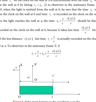
Figure 9, when the light is emitted from the wall at 0, he sees that the time t0 is rec-orded on the clock on the wall at 0 and time tx is recorded on the clock on the wall at x'. When the lightreaches the wall at x, the time 0
( )
v x c x t
c c
+ − should be
theoreti-cally recorded on the clock on the wall at 0, because it takes less time v x c
( )
c for light to travel the less distance v x c
( )
but time tx xc
+ is actually recorded on the clock on
the wall at x. To observers in the stationary frame S’, if
( )
0
x
v x c
x x
t t
c c c
+ = + − (17)
Figure 9. If the event happens in the coordinate x on the
x-axis on the moving frame S, then we can assume there is a box laid on the x-axis from 0 to x.
x O
O’ vt
x’
then the time tx on the clock on the wall at x is synchronized with the time t0 on the clock on the wall at 0 by letting
( )
0
x
v x c
t t
c
= − (18)
in the moving frame S. This means that the proper time is adjusted by t v x c
( )
c − atthe coordinate x when the proper time is t=t0 at the coordinate 0 in the moving frame S. The regular time t′ measured by observers in the stationary frame S’ is adjusted by
( )
( )
21 v x c
t v c
c
− −
due to time dilation, thus the relationship between these two coordinates is
( )
( )
21 v x c
t t v c
c
′ = − −
(19) Combining all relationships between coordinates of the moving frame S and the sta-tionary frame S’ forms the following reverse Lorentz transformation:
( )
2 1x′ − v c = −x vt (20)
y′ = y (21) z′ =z (22)
( )
( )
21 v x c
t t v c
c
′ = − −
(23)
6. An Example of Length Contraction and Time Dilation
Length contraction and time dilation between two inertial frames was discussed in the section IV. In the following example, we particularly select a blue light as the median to transmit message with wavelength
(
)
0
3 10 7
5000A 5 10 10 m 5 10 m
λ
= = × × − = × − (24)as the unit of length and period 7
15 8
5 10 m
1.667 10 sec 3 10 m sec
T c
λ −
−
×
= ≈ ≈ ×
× (25)
as the unit of time to construct 3-d s-t frames [9].
For a rod of length l0=70 m laid on the platform of a station and a train moving with velocity v=0.6c, the proper length of the rod measured from observers on the stationary frame S is l0=70 m, and the regular length of the rod measured from ob-servers on the moving frame S’
(
)
22 2 2
0 1 70 m 1 0.6 70 m 0.8 56 m
l=l −v c = − c c = × = (26) by length contraction.
then
(
)
7 7 7
0
0 7
70 m
14 10 14 10 14 10
5 10 m l
l λ λ
λ = × − = × → = × = × (27)
and
(
)
7 7 7
7 56 m
11.2 10 11.2 10 11.2 10
5 10 m l
l λ λ
λ = × − = × → = × = × (28)
These values with new units satisfies the formula of length contraction
(
)
(
)
(
)
2(
)
2 2 7 2 7
0 1 14 10 1 0.6 11.2 10
l=l −v c = ×
λ
− c c = ×λ
(29)It takes regular time
8 8
70 m 70 m
38.89 10 sec 0.6 0.6 3 10 m / sec
l t
v c
−
= = = = ×
× × (30) for the origin O’ of the moving frame S’ to pass from the left to the right ends of the rod measured by observers on the stationary frame S, thus the proper time measured from observers on the moving frame S’ is t0′ where
0 2 2 1 t t v c ′ =
− from time dilation formula. We can calculate the proper time
(
)
(
)
22 2 8 2 8
0 1 38.89 10 sec 1 0.6 31.11 10 sec.
t′ =t −v c = × − − c c = × − (31) In order to draw time into graph, we change the unit of time from sec to T. Because
8
7 15
38.89 10 sec
23.33 10 1.667 10 sec
t T − − × = = ×
× (32) then
(
7)
23.33 10
t= × T (33) and
8
7 0
15 31.11 10 sec
18.66 10 1.667 10 sec
t T
− −
′ = × = ×
× (34) then
(
7)
0 18.66 10
t′ = × T (35) These values with new units also satisfy the length contraction equation
(
)
(
)
2(
)
2 2 7 2 7
0 1 18.66 10 1 0.6 23.33 10
t=t′ −v c = × T − c c = × T (36) From Figure 10, it also shows that
θ
′ =θ
. Becausesinθ =18.66 23.33=0.799828546 (37)
then
(
)
1 0 0
sin 0.799828546 53.1137 53.11
θ
= − = ≈(38) and
Figure 10. A 3-d s-t stationary frame and a 3-d s-t moving frame λ = 5(10−7) m as the unit of length and T = 1.667(10−15) sec as the unit of time.
then
(
)
1 0 0
sin 0.799839228 53.1147 53.11
θ
′ = − = ≈ (40)This example shows that the actual value of time dilation and the actual value of length contraction can be measured simultaneously in this 3-d s-t frame by selecting λ as the unit for length and T as the unit for time [9].
7. Conclusions
In classical physics, time and space are treated independently. Einstein demonstrated the inseparability of time and space. The realistic difference between time and space is the single direction of time and the two directions of space. In the proposed 3-d s-t frame, time is represented by spheres of different radii with the origin of the space axes as their center and time can only have a single direction.
In Special Relativity, two 3-d s-t inertial frames can be constructed by choosing light as a medium for transmitting messages. The geometric meaning of time dilation of an event occurring at the same location in the moving frame for an observer in the statio-nary frame and length contraction of a rod lying still in the statiostatio-nary frame for an ob-server in the moving frame can be clearly illustrated in this 3-d s-t. The Lorenz trans-formation can also be derived from graphs of time dilation and length contraction. The universe generated from multiple big bangs based on a 3-d s-t frame solves the prob-lems which are unsolved by the universe generated from Big Bang. Time contraction and length contraction on the moving train helps us explain quantum entanglement. These demonstrate the value of 3-d s-t frames.
Acknowledgements
We would like to thank Elizabeth Chen, Min Chou, Zen-Fu Chow, Angel Garciel,
-40 -30 -20 -10 0 10 20 30 40 50
-10 0 10 20 30 40 50
18.66 23.33
18.66 14.925
14 2.8
11.2 107T
107λ θ θ’
Li-Shing Hsu, Bo Liu, Yaijei Sun, Chu-Tak Tseng, Chun-Zin Wu, Lin Wu, Wan-Zin Zhaw, Yousuo Zou for their support, encouragement, suggestions.
References
[1] Chen, T. and Chen, Z. (2016) The Shell Model of the Universe: A Universe Generated from Multiple Big Bangs. Journal of Modern Physics, 7, 611-626.
https://doi.org/10.4236/jmp.2016.77062
[2] Chen, T. and Chen, Z. (2005) Motions of Particles Described in a Three-Dimensional Space-Time Frame. The Proceeding of the Tenth Asian Technology Conference in Mathe-matics, Korea, 15-20 December 2005.
http://epatcm.any2any.us/EP/EP2005/2005P163/fullpaper.pdf
[3] Chen, T. (2006) The Heisenberg Uncertainty Relation Derived by Multiplying Matter Wa-velength and Light WaWa-velength. Concepts of Physics, III.
http://merlin.fic.uni.lodz.pl/concepts/2006_1/2006_1_1.pdf
[4] Chen, T. and Chen, Z. (2012) The Advantage of Three-Dimensional Space-Time Frames.
Frontiers in Sciences of Sciences, 2, 18-23.
http://www.sapub.org/journal/archive.aspx?journalid=1015&issueid=337
[5] Chen, T. and Chen, Z. (2016) Time, Length, Mass Are Derived Quantities. Journal of Mod-ern Physics, 7, No. 10. https://doi.org/10.4236/jmp.2016.710108
[6] Chen, T. and Chen, Z. (2016) A Bridge Connecting Classical Physics and Modern Physics.
Journal of Modern Physics, 7, 1378-1387. https://doi.org/10.4236/jmp.2016.711125 [7] Chen, T. and Chen, Z. (2008) A Pair of Inertial Frames versus an Inertial Frame. Concepts
of Physics, V, No. 3. http://merlin.fic.uni.lodz.pl/concepts/www/V_3/523.pdf
[8] Chen, T. and Chen, Z. (2008) The Paradox of Twins Described in a Three-Dimensional Space-Time Frame. The Proceeding of the Tenth Asian Technology Conference in Mathe-matics, Bangkok, Thailand, 15 December 2008.
http://atcm.mathandtech.org/EP2008/papers_full/2412008_15023.pdf
[9] Chen, T. and Chen, Z. (2009) Time Dilation and Length Contraction Shown in Three- Dimensional Space-Time Frames. Concepts of Physics, VI, No. 2.
http://merlin.phys.uni.lodz.pl/concepts/www/VI_2/221.pdf
Submit or recommend next manuscript to SCIRP and we will provide best service for you:
Accepting pre-submission inquiries through Email, Facebook, LinkedIn, Twitter, etc. A wide selection of journals (inclusive of 9 subjects, more than 200 journals)
Providing 24-hour high-quality service User-friendly online submission system Fair and swift peer-review system
Efficient typesetting and proofreading procedure
Display of the result of downloads and visits, as well as the number of cited articles Maximum dissemination of your research work
Submit your manuscript at: http://papersubmission.scirp.org/