ISSN: 1992-8645 www.jatit.org E-ISSN: 1817-3195
QUALITY-DRIVEN FEATURE IDENTIFICATION AND
DOCUMENTATION FROM SOURCE CODE
1
HAMZEH EYAL SALMAN, 2ABDELHAK-DJAMEL SERIAI, 3Mustafa Hammad
1
Mutah University 61710, Mutah, Karak, Jordan
2
LIRMM, UMR 5506 CC477 161 rue Ada, Montpellier, France
E-mail: [email protected], [email protected], [email protected]
ABSTRACT
Software companies develop a large number of software products cater to the needs of customers in different domains. Each product offers a set of features to serve customers in a particular domain. Over the time, the product features (resp. their implementations) should be improved, changed or removed to meet new demands of customers. Identifying source code elements that implements each feature plays a pivot role in such software maintenance tasks. In this article, we present an approach to support effective feature identification and documentation from source code. The novelty of our approach is that we identify each feature implementation based on a semantic-correctness model that can achieve satisfactory results according to well-known evaluation metrics on the subject. We have implemented our approach and conducted evaluation with a large case study. Our evaluation showed that our approach always achieves promising results.
Keywords: Feature Identification, Feature Location, Feature Documentation, Source Code, Reuse,
Re-engineering, Quality, Clustering.
1. INTRODUCTION
Software companies develop a large number of software products cater to the needs of customers in different domains. Each product offers a set of features to serve customers in a particular domain. A feature is a prominent or distinctive user-visible aspect, quality or characteristic of a software system
or systems [1]. Over the time, the product features
(resp. their implementations) should be improved, changed or removed to meet new demands of customers. Moreover, software products should be re-engineered to keep pace with technological developments in the software industry. Associating source code elements (e.g., classes, methods, etc.) that corresponds to each feature plays a pivot role in both software maintenance and re-engineering. This is because no maintenance or re-engineering activity can be completed performed without first
understanding and identifying functionalities
(features) provided by given source code [2]. Such
association is called as feature identification.
In the literature review, feature
identification is used interchangeably with other
concept called feature location [3][4]. However,
they are different concepts. The process of feature location relies on an input provided by the user to
the feature location process. This input represents information specific to the feature to be located and a guide of the feature location process. In contrast, the feature identification process works without such user input. We make a clear distinction between feature identification and location by
proposing the following definitions. Feature
location is a feature-driven process to locate a feature's implementation based on input
feature-specific information. Feature identification is a
source code-driven process to identify code elements potentially implement a feature based on
available source code information.
There is a large body of research on feature location approaches [5]. The distinguishing factor between these approaches is the type of information (user input) that they use. This type
refers to dynamic, static and textual information.
ISSN: 1992-8645 www.jatit.org E-ISSN: 1817-3195 In this article, we propose an approach
(called Feature Identification and Documentation, FID for short) for identifying source code elements that implement each feature. Our approach mainly relies on Agglomerative Hierarchical Clustering (AHC) to group source code elements into clusters based on semantic-correctness model. Each cluster represents a feature implementation. Then, the name and purpose of the feature implemented by such cluster are extracted.
We have implemented our approach and conducted evaluation with a large case study called
ArgoUML. Our evaluation shows that our approach
gives promising results according to the most
widely used metrics in the domain (Precision,
Recall and F-measure).
The remainder of the article is structured as follows. Section 2 reviews related work. Section 3 discusses our FID approach. Section 4 describes our experimental results and evaluation. Section 5 discusses threats to the validity of our approach. Finally, we conclude the article in Section 6.
2. RELATED WORK
In this section, we present the work that relates to ours. The majority of existing approaches are designed to support feature location while a few approaches support feature identification.
2.1 Feature Location Approaches
As mentioned earlier, the distinguishing factor between feature location approaches is the
type of information that they use: dynamic, static
and textual information. In the following, we
present feature location approaches according to these types of information.
2.1.1 Dynamic-based feature location
approaches
Dynamic analysis refers to collecting information from a system during runtime. For the purpose of feature location, it is used to locate feature implementations that can be called during runtime by test scenarios [6][7]. Feature location using dynamic analysis depends on the analysis of execution traces. An execution trace is a sequence of source code entities (classes, methods, etc.). Usually, one or more feature-specific scenarios are developed that invoke only the implementation of the feature of interest. Then, the scenarios are run and execution traces are collected, recording information about the code
that was invoked. These traces are obtained by instrumenting the system code. Using dynamic analysis, the source code elements pertaining to a feature can be determined in several ways. Comparing the traces of the feature of interest to other feature traces in order to find source code elements that only is invoked in the feature-specific traces[8][9]. Alternatively, the frequency of execution parts of source code can be analyzed to determine the implementation of a feature [10][11]. For example, a method exercised multiple times and in different situations by test scenarios relevant to a feature is more likely to be relevant to the feature being located than a method used less often.
Feature location by using dynamic analysis has some limitations. The test scenarios used to collect traces may invoke some but not all the code portions that are relevant to a given feature; this means that some of the implementation of that feature may not be located. Moreover, it may be difficult to formulate a scenario that invokes only the required feature, which leads to
obtain irrelevant source code elements.
Additionally, developing test scenarios involves well-documented systems to understand the system functionalities [5]. Such maintainers may not always be available, especially in legacy system.
2.1.2 Static-based feature location
approaches
Feature location using static analysis refers to the analysis of the source code to explore structural information such as control or data flow dependencies. Static feature location approaches require not only dependence graphs, but also a set of source code elements which serve as a starting point for the analysis. This initial set is relevant to features of interest and usually specified by maintainers. The role of static analysis is to determine other source code elements relevant to the initial set using dependency graphs [12] [13] [14] [15] [16] [17][4][18] [19].
ISSN: 1992-8645 www.jatit.org E-ISSN: 1817-3195 a feature may catch source code elements that are
irrelevant. In addition, static approaches need maintainers who are familiar with the code in order to determine the initial set.
2.1.3 Textual-Based feature location
approaches
Textual information embedded in source code comments and identifiers provides important guidance about where features are implemented. Feature location using textual analysis aims to analyze this information to locate a feature's implementation [20]. This analysis is performed by
three different ways: pattern matching (PM),
Natural Language Processing (NLP) and
Information Retrieval (IR).
PM usually needs a textual search inside a
given source code using a utility tool, such as grep
[21]. Maintainers formulate a query that describes a feature to be located then they use a PM tool to investigate lines of code that match the query. The PM is not very precise due to the vocabulary problem; the probability of choosing a query's terms, using unfamiliar source code maintainers, that match the source code vocabulary is relatively low [22].
NLP-based feature location approaches analyze the parts of the words (such as noun phrases, verb phrases and prepositional phrases) used in the source code [23]. They rely on the assumption that verbs in object-oriented programs correspond to methods, whereas nouns correspond to objects. As an input for these approaches, the user formulates a query describing the feature of interest and then the content of the query is
decomposed into a set of pairs (verb, object). These
approaches work by finding methods and objects inside the source code, which are similar to the input verbs and objects, respectively [24][25][26]. NLP is more precise than pattern matching but relatively expensive [5].
IR-based techniques, such as Latent Semantic Indexing (LSI) and Vector Space Model (VSM), are textual matching techniques to find textual similarity between a query and given corpus of textual documents. For the purpose of locating a feature's implementation, a feature's description represents the subject of a query while source code documents represent corpus documents. A feature
description is a natural language description consisting of short paragraph(s). A source code document contains textual information of certain granularity of source code, such as a method, a class or a package. IR-based feature location approaches find a code portion that is relevant to the feature of interest by conducting a textual matching between identifiers and comments of a given source code portion and the description of the feature to be located [27] [28] [29] [30] [31] [32] [33][34][35]. IR lies between NLP and pattern matching in terms of accuracy and complexity [5].
Regardless of the type of textual analysis used (PM, NLP and IR), generally the quality of these approaches mainly depends on the quality of the source code naming conventions and the query.
2.2 Feature Identification Approaches
In the literature review, there are only three approaches to support feature identification from source code [36][37][38]. These approaches are as follows.
In [36], Ziadi et al. propose an approach to
identify portions of source code elements that potentially may implement features in a collection
of similar software products called product
variants. These products have common features and
differ in others. The authors exploit what product variants have in common at the source code level by performing several rounds of intersections among source code elements of product variants. In the first round, the source code elements shared between all product variants are obtained. In the next rounds, source code elements shared among some product variants are obtained. The result of each intersection may potentially represent feature implementation(s).
According to Ziadi et al. approach, they
ISSN: 1992-8645 www.jatit.org E-ISSN: 1817-3195
Figure 1: Overview of FID Process.
software products and cannot be applied to only one software product.
In [37], Al-Msie'Deen et al. propose an
approach similar to Ziadi et al.'s approach. Their
approach exploits common source code elements across product variants to identify segments of source code elements, which potentially may implement features. They rely on Formal Concept Analysis (FCA) for conducting several intersections between source code elements of product variants to identify these segments. Then, these segments are further divided into sub-segments using LSI and FCA. According to their approach, each sub-segment represents a feature implementation.
However, it is not necessary that each sub-segment represents an implementation of a single feature because source code elements that are shared between the implementation of two or more features appear as a separated sub-segment. This leads to identify features more than the features actually provided by a given collection of product variants, and hence missing source code elements that are relevant to features that actually are provided by this collection. Moreover, their approach was designed to work only in case of having a set of similar software products and cannot be applied to only one software product.
In [38], Grant et al. relies on Independent
Component Analysis (ICA) to identify feature implementations. ICA is a signal analysis technique that decomposes input signals into statistically independent components. According to their approach, a term-document matrix is constructed. In this matrix, rows correspond to
source code methods, columns represent terms extracted from methods and cells contain the frequency of a term in a method. Then, ICA factors the matrix into two new matrices. The first matrix holds independent signals which may be considered as features. The second matrix stores information about how each signal is relevant to a method. Features are then mapped to methods which are related in functionality. The limitations of their approach are redundancy in the search results and identifying only a few features.
3. THE PROPOSED FEATURE
IDENTIFICATION PROCESS
In this section, we present step-by-step the proposed feature identification process. According to this process, we identify each feature implementation with its name in three steps as detailed in the following. These steps are designed by considering that each feature is implemented by a set of source code classes. This consideration comes from the granularity level of source code elements that implement features in large systems. This level in such systems is a coarse-granularity
which refers to packages and classes.
ISSN: 1992-8645 www.jatit.org E-ISSN: 1817-3195
3.1 Source Code Analysis
In this step, we analyze the input source code to extract packages, classes and interdependencies information among these classes which are used in the remaining steps. These interdependencies include:
Inheritance relationship: when a class
inherits attributes and methods from another class.
Composition relationship: when a class is
used as a data type of attribute belonging to another class.
Method call: when a method of one class
calls a method of another class.
Direct attribute access: when a class
accesses an attribute of another class.
Shared attribute access: when two classes
access the same attribute of another class.
For example, classes (A and B) accesses
the same attribute (AT) that belongs to the
class C.
To capture these interdependencies, we statically analyze the source code through building an abstract syntax tree (AST) [39]. This tree is traversed to extract interdependencies mentioned above.
3.2 Clustering
The main goal in our feature identification process is to group together the source code classes that contribute to implement the same feature into a cluster. To achieve this goal, we propose the
following two types of clustering: Clustering Based
on Feature List and Clustering Based on
Semantic-Correctness.
3.2.1 Clustering based on feature list
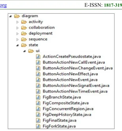
Features represent domain concepts which their implementations are provided in software documentation, such as package diagram and class diagram [40]. For example, in UML software tools,
such as ArgoUML, the implementation of domain
concepts are organized into folders according to
package names, such as activity, collaboration,
sequence, deployment and state (cf. Figure 2). Thus,
[image:5.612.312.517.73.293.2]the features implementations are often organized into packages which are represented as folders or sub-folders. A package folder consists of many
Figure 2: Software Features by Package Names.
related classes corresponding to the related features.
For instance, in ArgoUML there is a feature called
state. By reference to the Figure 2, we can find a
folder package under title “state” and this term occurs frequently within the names of classes of
that packages (e.g., FigBranchState, FigFinalState,
FigForkState).
In this type of clustering, we aim to repackaging source code packages and sub-packages according to the input feature names. Repackaging refers to grouping together packages and sub-packages (resp. their classes) which their names include a feature name into a cluster. Such cluster represents a part of the implementation of
that feature. Such clusters called feature clusters.
For other packages that their names do not include feature names, we create a cluster for each class belonging to these packages, such clusters called
singleton clusters. Both feature and singleton
clusters represent initial clusters for the next type of clustering as shown below.
3.2.2 Clustering based on
semantic-correctness
In this type of clustering, we group the
initial clusters to identify each feature
ISSN: 1992-8645 www.jatit.org E-ISSN: 1817-3195
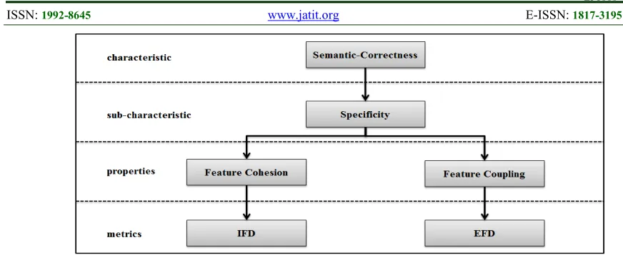
Figure 3: Meta Model to Measure Software Characteristics in ISO-9126.
algorithm which uses this function to identify each feature implementation.
3.2.2.1 Semantic-correctness of features
Semantic-correctness of a feature means that each feature implementation is semantically correct. In order to evaluate the feature semantic-correctness, we use the refinement model given by
the norm ISO-9126 [41] (cf. Figure 3). According
to this model, we need to refine the semantic-correctness characteristic into sub-characteristics. This refinement is done by studying the semantic which is associated with the feature concept. This study is based on the most commonly admitted definitions of the feature concept [42]. Based on these studied definitions, we identify the following
semantic sub-characteristic of a feature: specificity
which means that a feature must provide a limited number of closely related functionalities.
Then, according to norm ISO-9126, we refine this sub-characteristic into feature properties.
These properties are featurecohesion and coupling.
Feature cohesion is the degree to which the elements of a feature (e.g., classes, methods and fields) depend on other elements of the same feature while feature coupling is the degree to which the elements of a feature depend on elements outside the feature [43]. These two properties indicate the level of proximity between the internal elements of the feature implementation. Thus, they determine if the internal elements of a feature implementation work together to accomplish closely related functionalities or if there are
independent elements providing different
functionalities. In order to measure the feature
properties, we use two metrics proposed by Apel et
al. [43]. Internal-ratio Feature Dependency to
measure feature cohesion and External-ratio
Feature Dependency to measure feature coupling.
Internal-ratio Feature Dependency
(IFD) measures the number of internal
dependencies in relation to the total number of
potentially possible internal dependencies of a feature implementation:
Function intdep(F) returns all
interdependencies among elements of a feature
implementation F; |elems(F)|2 is the maximum
possible number of interdependencies among
elements of a feature implementation F. The
intuition behind this measure is that the elements of a cohesive feature depend on many other elements of the same feature. So, for a feature F with three
elements each depending on all elements of F
(including self-references), we have IFD (F) = 1,
which indicates that F is maximally cohesive.
Conversely, for a feature F with three elements,
none depending on any other element of F, we have
IFD (F) = 0, which indicates that F is not cohesive.
External-ratio Feature Dependency
(EFD) measures the number of interdependencies
in relation to the total number of actual dependencies (internal and external) of a feature implementation:
Function dep (F) returns all dependencies
of elements of a feature implementation F. If F
depends only on itself, we have EFD (F) = 1,
which indicates that F is tightly coupled (i.e., the
elements of F use each other). Conversely, if a
feature F depends only on elements outside the
feature, we have EFD (F) = 0, which indicates that
F is loosely coupled.
The linear combination of IFD and EFD
represents our fitness function (Spe(F)) (see
Equation 3). The links previously established
between the feature’s characteristic,
sub-characteristic, properties and metrics are
ISSN: 1992-8645 www.jatit.org E-ISSN: 1817-3195
Figure 4: The Refinement Model for Semantic-Correctness of a Feature Implementation.
3.2.2.2 Hierarchical clustering algorithm
As each feature implementation consists of a set of classes, it is necessary to group together these classes that belong to the same feature implementation. This association must be based on a number of criteria to maximize the value of the fitness function of these groups. In addition to the fitness function, it is necessary to define an algorithm which allows us to identify groups of classes. Among the possible algorithms, we use a clustering algorithm. This kind of algorithm is used for grouping elements using a similarity function. This makes it suitable for our problem because the fitness function defined previously will play the role of a similarity function.
Clustering, in general, is a division of objects into groups of similar objects. Each group, called cluster, consists of objects that are similar among themselves and dissimilar to objects of other clusters. Clustering approaches are classified into hierarchical or non-hierarchical [44]. Hierarchical clustering algorithms are further categorized into agglomerative (bottom-up) and divisive (top-down). An Agglomerative Hierarchical Clustering (AHC) starts with one-object (singleton) clusters and recursively merges two or more appropriate clusters. A divisive clustering involves a series of successive divisions.
Our approach uses an AHC algorithm (cf.
Algorithm 1) for grouping the initial clusters (produced previously in Step 2.1). The strength of the relationship between these clusters is used as a basis for clustering them (Line 3). This strength is
measured using our fitness function (Spc()). The
Algorithm 1proceeds through a series of successive binary mergers (agglomerations), initially of individual entities (the initial clusters) and later of clusters formed during the previous stages (Lines 4-7). The clusters having the highest relationship strengths are grouped first. The process continues until we get a single cluster. We obtain from this single cluster a dendrogram (Line 9). This
dendrogram contains all candidate feature
implementations. The presented algorithm uses the
closestClusters() function to determine which two
clusters will be merged in the next step. This function returns the most similar pair of clusters (the two clusters that maximize the value of the
ISSN: 1992-8645 www.jatit.org E-ISSN: 1817-3195 Figure 5 shows an example of dendrogram
tree. At the lowest level, each initial cluster is in its
Figure 5: An Example of a Dendrogram Tree.
own cluster. At the highest level, all clusters belong to the same cluster. The internal nodes represent new clusters formed by merging the clusters that appear as their children (left and right nodes) in the tree.
In order to obtain each feature
implementation, we have to select nodes among the hierarchy resulting from the dendrogram tree. This
selection is done by an algorithm based on a
depth-first search (cf. Algorithm 2).
Algorithm 2 is a simple algorithm to select nodes representing feature implementations. The algorithm traverses the dendrogram tree starting
from the root node. In each while loop, the
traversed nodes are sorted in ascending order according to the value of the fitness function of each node (Line 4). Then, the node that has the lowest fitness function value (i.e., the relationship strengths between its left and right nodes is the lowest) is firstly exploded to its left and right nodes (Lines 5-9). The loops continue until reaching the
number of traversed nodes (stored in
traversedNodes stack) are equal to the number of
features. As a result, the presented algorithm returns a set of nodes so that each one represents a feature implementation.
3.3 Documenting Feature Implementations
Identified
In case of having a large number of features, we need to document each feature implementation identified in order to link this implementation with its feature name (as input). Moreover, a feature implementation can be efficiently reused if its documentation (e.g., main purpose, name, etc.) is available. Thus, the need to document the feature implementation identified is necessary.
To achieve above mentioned goal, we use
a heuristic to document each feature
implementation identified. We based ourselves on the following observation: in many object-oriented languages, class names are a sequence of nouns concatenated using a CamelCase convention (i.e.,
CollaborationDiagramPropPanelFactory,
DeploymentDiagramGraphModel, etc). The first
word of a class name denotes to the main purpose of the class; the other words denote to a complementary purpose of the class. According to the previous assertion, our heuristic documents each feature implementation in three steps [45]:
extracting and decomposing class names from
feature implementation, weighting words and
constructing the feature name.
3.3.1 Extracting and decomposing class
names
[image:8.612.89.296.491.653.2]ISSN: 1992-8645 www.jatit.org E-ISSN: 1817-3195
example:CollaborationDiagramPropPanelFactory
is split into Collaboration, Diagram, Prop, Panel
and Factory. However, we may encounter single
case class name (such as, DBNAME and
maxvalues), abbreviations and acronyms. To handle
such name compositions, we rely on an algorithm
proposed by Warintarawej et al. [40].
3.3.2 Weighting words
In this step, a weight is assigned to each token extracted from class names. A large weight is assigned to the first token of a class name. A medium weight is assigned to the second token of a class name. Finally, a small token is assigned to other tokens. For a given token (t), the weight is calculated as follows:
Where:
N1: number of appearance of the token(t)
as the first token of a class name.
N2: number of appearance of the token(t)
as the second token of a class name.
N3: number of appearance of the token(t)
as the third token of a class name.
3.3.3 Constructing the feature name
In this step, a feature name is constructed based on the strongest weighted tokens. The first word of the feature name is the strongest weighted token. The second word of the feature name is the second strongest weighted token and so on. The number of words used in the feature name is specified by the user. When many tokens have the same weight, all the possible combinations are given to the user and he can select the appropriate one.
4. EXPERIMENTAL EVALUATION
In this section, we present an experimental evaluation of our feature identification and documentation process (FID) to demonstrate its feasibility.
4.1 Case Study
We have applied FID to a large case study
called ArgoUML. It is a JAVA open-source which
is used to design all standard UML diagrams, such
as, the Class diagram, the State diagram, the
Activity diagram, etc. We use ArgoUML because its
features are well-documented and each feature implementation can be extracted from the system for evaluation. This allows us to investigate the scalability of FID and the quality of FID results.
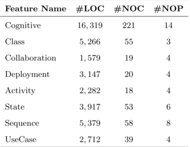
ArgoUML supports eight complex
features. The first feature is cognitive support
which provides information that helps designers to detect and to solve problems in their models. Other
features are Class Diagram, State Diagram,
Activity Diagram, Collaboration Diagram,
Sequence Diagram, Deployment Diagram and
UseCase Diagram. These features provide to
support their respective UML diagrams.
In order to establish the ground truth links
between ArgoUML's features and their
implementing source code classes for evaluation purpose, we relied on the work proposed by Marcus
et al. [46]. In this work, each feature
implementation is annotated using conditional
compilation directives (e.g., #if defined
(COGNITIVE)). Insertion such pre-processor
directives in the source code allows us to delimit
each feature implementation in ArgoUML.
ArgoUML's implementation has about 120
KLOC. From those lines, 37 KLOC were annotated
as responsible for the implementation of the aforementioned features. Such numbers refer to that ArgoUML is an appropriate case study for scalability. Table 1 and Table 2 present source code
statistic information for ArgoUML and its features.
4.2 Evaluation Metrics
We use three metrics to evaluate the
effectiveness of our approach: Precision, Recall
and F-measure. These metrics are well-known in
our domain [5].
For a given feature, Precision is the
percentage of relevant source code classes retrieved to the total number of retrieved classes. The
ISSN: 1992-8645 www.jatit.org E-ISSN: 1817-3195
Precision value is 1, this means that all the
retrieved classes are relevant but also this does not mean that all relevant classes are retrieved (false-negative classes). Equation 5 represents the
Precision metric equation.
For a given feature, Recall is the
percentage of relevant classes retrieved to the total
number of relevant classes. The Recall values take
a range in [0, 1]. If the Recall value is 1, this means that all relevant classes are retrieved. However, this does not mean that all retrieved classes are relevant (false-positive classes). Equation 6 represents the
Recall metric equation.
F-measure is the harmonic mean of Precision and
Recall. It is computed as follows:
The F-measure values take a range in [0,
1]. If F-measure value is 0, it means that no
relevant classes have been retrieved. If F-measure value is 1, it means that all relevant classes are retrieved and only them. Moreover, the harmonic mean (F-measure) gives a high value only when
both Recall and Precision are high. Therefore, a
high value of F-measure can be interpreted as an attempt to find the best possible compromise
between Recall and Precision.
4.3 Results and Effectiveness
Table 3 presents experiment results of
Precision, Recall and F-measure on ArgoUML. The
first column refers to each feature implementation identified. The last column shows the name that is assigned by our approach to each feature implementation. For example, the implementation
(Imp.) of Collaboration feature is documented as a
feature name called FigureDiagramCollaboration.
For Precision metric, our approach
achieves (100%) Precision for identifying all
feature implementations except Cognitive's Imp.
which has 88% Precision. These high Precision
values are due to the fact that each feature
implementation in ArgoUML is cohesive. This means that each feature implementation maximize the value of the fitness function. Consequently, our approach deals with such cohesive implementation as an implementation of one feature and only for
that feature. Regarding to the Precision value
(88%) of Cognitive's Imp., we think that this is due
to Cognitive feature (resp. its implementation) has a
crosscutting behavior through all other features (resp. their implementations). This means that the
elements of Cognitive's implementation are loosely
coupled which causes our approach to retrieve
some irrelevant classes for Cognitive feature.
According to Recall metric, the proposed
approach has high Recall values. They take a range
[91% - 100%] for most of the features, Class
Diagram, Activity Diagram, Sequence Diagram,
Deployment Diagram and UseCase Diagram while
Collaboration's Imp. and State's Imp. have 57% and
73%Recall respectively. The reason that hinders
our approach achieving 100% for all feature
implementations identified is that we do not
consider overlapping among feature
[image:10.612.323.519.192.344.2]ISSN: 1992-8645 www.jatit.org E-ISSN: 1817-3195 implementations together, we can consider such
minor degrade in Recall values are not significant.
F-measure values shown in Table 3 are
high where these values take a range in [73% -
100%]. These values confirm that our approach
gives a good compromise between Precision and
Recall. This is attributed to the fact that our
approach achieves high Precision and Recall values
for each feature implementation identified.
The last column in Table 3 shows the feature name extracted from each feature implementation according to our approach. Each feature name consists of three terms. This number of terms can be increased or decreased based on the human expert need. It is important to note that by using only three terms, we can associate each feature implementation identified with its correct
feature name in ArgoUML. For example, the
Class's Imp. is associated with Class feature
because the name (Figure Class diagram) extracted
from the Class's Imp. includes the term “Class”.
Also, this is true for other feature except Cognitive.
The name (Critics To Go) assigned to Cognitive's
Imp. does not include the “Cognitive” term but it
includes the term “Critics” which refers to
Cognitive feature according to ArgoUML
documents.
5. THREATS TO VALIDITY
We identify two issues that constitute limitations of our study and impact the results.
Our approach uses agglomerative
hierarchical clustering to group source classes into non-overlapping clusters so that each resulting cluster represents a feature implementation. However, feature implementations can be interleaved (there are shared classes between feature implementations). Such interleaving may impact the results slightly.
In our approach, we rely on quality metrics
which consist of feature cohesion and coupling to design our fitness function. This function is used to guide the hierarchical clustering to find a feature implementation which maximizes the
fitness value. However, feature
implementations that need to be identified may have low cohesion and coupling,
especially in ad-hoc implementation. This may impact the results.
6. CONCLUSIONS AND PERSPECTIVES
In this article, we presented an approach called FID for automatically supporting feature identification and documentation from source code. Our approach mainly relied on agglomerative hierarchical clustering to group source code classes into clusters based on semantic-correctness model. Also, we documented each feature implementation by automatically generating its name using some heuristics based on well accepted code convention. In our experimental evaluation using a large case
study called ArgoUML, we showed that our
approach always achieves promising results according to the widely used metrics in our domain:
Precision, Recall and F-measure.
In the future, we are interested to investigate textual information embedded in source code (e.g., identifier names) as a complementary part of our fitness function. This is because such information conveys domain concepts (feature) software.
REFERENCES
[1] K. C. Kang, S. G. Cohen, J. A. Hess, W. E. Novak, and A. S. Peterson, “Feature-oriented domain analysis (foda) feasibility study,” 1990.
[2] B. Dit, M. Revelle, M. Gethers, and D. Poshyvanyk, “Feature location in source code: a taxonomy and survey,” Journal of Evolution and Process, vol. 25, no. 1, 2013, pp. 53–95. [3] G. Antoniol and Y.-G. Gueheneuc, “Feature
identification: a novel approach and a case study,” in Software Maintenance, 2005. ICSM’05. Proceedings of the 21st IEEE International Conference on, Sept 2005, pp. 357–366.
[4] M. Trifu, “Using dataflow information for concern identification in object-oriented software systems,” in Proceedings of the 2008 12th European Conference on Software Maintenance and Reengineering, ser. CSMR ’08. Washington, DC, USA: IEEE Computer Society, 2008, pp. 193–202.
ISSN: 1992-8645 www.jatit.org E-ISSN: 1817-3195 [6] R. Koschke and J. Quante, “On dynamic feature
location,” in Proceedings of the 20th
IEEE/ACM international Conference on Automated software engineering, ser. ASE ’05, New York, NY, USA, 2005, pp. 86–95. [7] F. Asadi, M. Penta, G. Antoniol, and Y.-G.
Gueheneuc, “A heuristic-based approach to identify concepts in execution traces,” in Proceedings of the 2010 14th European Conference on Software Maintenance and Reengineering, ser. CSMR ’10, Washington, DC, USA, 2010, pp. 31–40.
[8] T. Eisenbarth, R. Koschke, and D. Simon, “Locating features in source code,” IEEE Trans. Softw. Eng., vol. 29, no. 3, 2003, pp. 210–224.
[9] N. Wilde and M. C. Scully, “Software reconnaissance: mapping program features to code,” Journal of Software Maintenance: Research and Practice, vol. 7, no. 1, 1995, pp. 49–62.
[10] A. D. Eisenberg and K. De Volder, “Dynamic feature traces: Finding features in unfamiliar code,” in Proceedings of the 21st IEEE
International Conference on Software
Maintenance, ser. ICSM ’05, Washington, DC, USA, 2005, pp. 337–346.
[11] H. Safyallah and K. Sartipi, “Dynamic analysis of software systems using execution pattern mining.” in ICPC. IEEE Computer Society, 2006, pp. 84–88.
[12] C. Kunrong and R. Vclav, “Case study of feature location using dependence graph,” in In Proceedings of the 8th International Workshop on Program Comprehension. IEEE Computer Society, 2000, pp. 241–249. [13] J. Buckner, J. Buchta, M. Petrenko, and V.
Rajlich, “Jripples: A tool for program comprehension during incremental change,” in Proceedings of the 13th International Workshop on Program Comprehension, ser. IWPC ’05. Washington, DC, USA: IEEE Computer Society, 2005, pp. 149–152. [14] M. P. Robillard and G. C. Murphy, “Concern
graphs: finding and describing concerns using
structural program dependencies,” in
Proceedings of the 24th International
Conference on Software Engineering, ser. ICSE ’02. New York, NY, USA: ACM, 2002, pp. 406–416.
[15] M. Robillard and G. C. Murphy, “Representing concerns in source code,” ACM Transactions on Software Engineering and Methodology, vol. 16, no. 1, pp. 2007, 1–38.
[16] M. P. Robillard, “Automatic generation of
suggestions for program investigation,”
SIGSOFT Softw. Eng. Notes, vol. 30, no. 5, Sep. 2005, pp. 11–20.
[17] Z. M. Saul, V. Filkov, P. Devanbu, and C. Bird,
“Recommending random walks,” in
Proceedings of the the 6th Joint Meeting of
the European Software Engineering
Conference and the ACM SIGSOFT
Symposium on The Foundations of Software Engineering, ser. ESEC-FSE ’07. New York, NY, USA: ACM, 2007, pp. 15–24.
[18] A. El Kharraz, P. Valtchev, and H. Mili, “Concept analysis as a framework for mining functional features from legacy code,” ser. ICFCA’10. Springer-Verlag, 2010, pp. 267– 282.
[19] M. Marin, A. V. Deursen, and L. Moonen, “Identifying crosscutting concerns using fan-in analysis,” ACM Trans. Softw. Eng. Methodol., vol. 17, no. 1, Dec. 2007, pp. 3:1– 3:37.
[20] T. Savage, M. Revelle, and D. Poshyvanyk, “Flat3: feature location and textual tracing tool.” in ICSE’2. ACM, 2010, pp. 255–258. [21] M. Petrenko, V. Rajlich, and R. Vanciu, “Partial
domain comprehension in software evolution and maintenance,” in The 16th IEEE Int’l Conf. on Program Comprehension. IEEE, June 2008, pp. 13–22.
[22] G. W. Furnas, T. K. Landauer, L. M. Gomez, and S. T. Dumais, “The vocabulary problem in human-system communication,” Commun. ACM, vol. 30, no. 11, 1987, pp. 964–971. [23] D. Shepherd, L. Pollock, and K. Vijay-Shanker,
“Towards supporting on-demand virtual remodularization using program graphs,” in
Proceedings of the 5th International
Conference on Aspect-oriented Software Development, ser. AOSD ’06, New York, NY, USA, 2006, pp. 3–14.
[24] S. L. Abebe and P. Tonella, “Natural language parsing of program element names for concept extraction,” in Proceedings of the 2010 IEEE 18th International Conference on Program Comprehension, ser. ICPC ’10. Washington, DC, USA: IEEE Computer Society, 2010, pp. 156–159.
[25] M. Petrenko, V. Rajlich, and R. Vanciu, “Partial domain comprehension in software evolution and maintenance,” in The 16th IEEE Int’l Conf. on Program Comprehension. IEEE, June 2008, pp. 13–22.
ISSN: 1992-8645 www.jatit.org E-ISSN: 1817-3195 queries,” in Proceedings of the 32Nd
ACM/IEEE International Conference on Software Engineering - Volume 1, ser. ICSE ’10. New York, NY, USA: ACM, 2010, pp. 165–174.
[27] A. D. Lucia, F. Fasano, R. Oliveto, and G. Tortora, “Recovering traceability links in software artifact management systems using information retrieval methods,” ACM Trans. Softw. Eng. Methodol., vol. 16, no. 4, 2007. [28] G. Antoniol, G. Canfora, G. Casazza, A. De
Lucia, and E. Merlo, “Recovering traceability links between code and documentation,” IEEE Trans. Softw. Eng., vol. 28, no. 10, Oct. 2002, pp. 970–983.
[29] G. Gay, S. Haiduc, A. Marcus, and T. Menzies, “On the use of relevance feedback in ir-based concept location.” in ICSM. IEEE, 2009, pp. 351–360.
[30] A. Marcus and J. I. Maletic, “Recovering
documentation-to-source-code traceability
links using latent semantic indexing.” in ICSE. IEEE Computer Society, 2003, pp. 125–137.
[31] A. Kuhn, S. Ducasse, and T. G´ırba, “Semantic clustering: Identifying topics in source code,” Inf. Softw. Technol., vol. 49, no. 3, , Mar. 2007, pp. 230–243.
[32] A. D. Lucia, R. Oliveto, and G. Tortora, “Ir-based traceability recovery processes: An empirical comparison of ”one-shot” and incremental processes,” in Proceedings of the
2008 23rd IEEE/ACM International
Conference on Automated Software
Engineering, ser. ASE ’08, Washington, DC, USA, 2008, pp. 39–48.
[33] M. Hammad, “Identifying related commits from software repositories,” International Journal of Computer Applications in Technology, vol. 51, no. 3, 2015, pp. 212–218.
[34] A. De Lucia, R. Oliveto, and G. Tortora, “Adams re-trace: Traceability link recovery via latent semantic indexing,” in Proceedings of the 30th International Conference on Software Engineering, ser. ICSE ’08. New York, NY, USA: ACM, 2008, pp. 839–842. [35] H. Eyal-Salman, A.-D. Seriai, and C. Dony,
“Feature-to-code traceability in a collection of software variants: Combining formal concept analysis and information retrieval,” ser. IRI’13. California, USA: IEEE Computer Society, 2013, pp. 209–216.
[36] T. Ziadi, L. Frias, M. A. A. da Silva, and M. Ziane, “Feature identification from the source code of product variants,” in Proceedings of
the 15th European Conference on Software Maintenance and Reengineering, F. R. MENS T., CLEVE A., Ed. Los Alamitos, CA, USA: IEEE, 2012, pp. 417–422.
[37] R. Al-Msie’Deen, A. Seriai, M. Huchard, C. Urtado, S. Vauttier, and H. Eyal Salman, “Mining features from the object-oriented source code of a collection of software variants using formal concept analysis and latent semantic indexing,” in The 25th
International Conference on Software
Engineering and Knowledge Engineering.
Knowledge Systems Institute Graduate
School, 2013, p. 8-18
[38] S. Grant, J. R. Cordy, and D. B. Skillicorn,
“Automated concept location using
independent component analysis.” in WCRE. IEEE Computer Society, 2008, pp. 138–142. [39] B. Fluri, M. Wuersch, M. PInzger, and H. Gall,
“Change distilling: Tree differencing for
fine-grained source code change extraction,” IEEE Trans. Softw. Eng., vol. 33, no. 11, 2007, pp. 725–743.
[40] P. Warintarawej, M. Huchard, M. Lafourcade, A. Laurent, and P. Pompidor, “Software understanding: Automatic classification of
software identifiers,” Intelligent Data
Analysis, vol. 18, no. 6, 2014.
[41] ISO, “Software engineering - product quality, ISO/IEC 9126-1,” International Organization for Standardization, Tech. Rep., 2001. [42] M. Acher, “Managing Multiple Feature Models:
Foundations, Language, and Applications,” Ph.D. dissertation, University of Nice Sophia Antipolis, Nice, France, sep 2011.
[43] S. Apel and D. Beyer, “Feature cohesion in software product lines: an exploratory study,” ser. ICSE ’11. ACM, 2011, pp. 421–430. [44] P. Berkhin, “A survey of clustering data mining
techniques,” Grouping Multidimensional
Data, 2006, pp. 25–71.
[45] S. Kebir, A.-D. Seriai, S. Chardigny, and A.
Chaoui, “Quality-centric approach for
software component identification from
object-oriented code,” ser. WICSA-ECSA ’12. Washington, DC, USA: IEEE Computer Society, 2012, pp. 181–190.