PERFORMANCE OF SEPARATE RANDOM USER
SCHEDULING (SRUS) AND JOINT USER SCHEDULING
(JUS) IN THE LONG TERM EVOLUTION – ADVANCED
AHMED A ALI, ROSDIADEE NORDIN, HUDAABDULLAH
DEPARTMENT OF ELECTRICAL, ELECTRONIC AND SYSTEMS ENGINEERING, Faculty of Engineering & Built Environment
UNIVERSITIKEBANGSAAN MALAYSIA (UKM). E-mail: [email protected]
ABSTRACT
Carrier aggregation (CA) is one of the main features in Long Term Evolution– Advanced (LTE-A). CA will allow the target peak data rates in excess of 1 Gbps in the downlink and 500 Mbps in the uplink to be achieved and the users can have access to the total bandwidth of up to 100 MHz. The system bandwidth may be continuous or system consisting of several parts of non-continuous aggregated bandwidth. This paper provides a summary of the supported CA scenarios as well as an overview of the advanced functionality of CA-LTE with particular emphasis on the basic concept, control mechanisms, and the performance aspects of (CA). This paper also demonstrates how CA can be used as an enabler for simple yet effective frequency domain interference management schemes. In particular, the interference management is to provide the intervention made significant gains in heterogeneous networks, envisioning intrinsically uncoordinated deployments from the home base stations. Then, we compared the quality of service (QoS) performances of two different multi-user scheduling schemes in CA based LTE-A systems, separated random user scheduling (SRUS) and joint user scheduling (JUS). The former is simpler but less efficient, whereas the latter is optimal but with higher overheadsignaling. Moreover, only one single component carrier (CC) is required to access for user equipment (UE) in the case of SRUS, while all the CCs must be connected in the case of JUS. Some technical challenges for implementing carrier scheduling schemes technique in LTE-A systems, are discussed and highlighted.
Keywords: Long Term Evolution– Advanced, Carrier Aggregation, Separated Random User Scheduling,
Joint User Scheduling.
1. INTRODUCTION
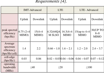
In order to achieve up to 1 Gbit/s peak data rate in the fourth generation (4G) mobile systems, carrier aggregation (CA) technology is introduced by the 3rd generation partnership project 3GPP to support wider transmission bandwidths up to 100 MHz in its new LTE-A standards [1–2]. According to specific technical and performance requirements defined in [3], this feature allows for expansion in bandwidth scalable by assembling multiple component carriers (CCs). This aggregated carrier can be configured with different bandwidths, and can be in the same frequency bands (contiguous) or different (non-contiguous) to provide maximum flexibility in using rare radio resources network to operators, While preserving compatibility on legacy LTE Release 8 users .with carrier aggregation, users can access to the bandwidth with much larger transmission bandwidth up 100 MHz in LTE Release 10, compared to the LTE Release 8
standards. Carrier aggregation allows the user to schedule on multiple CCs simultaneously; each may exhibit different radio channel properties [4]. Table 1 compares the peak average and cell-edge spectrum efficiency requirements of the LTE, LTE-Advanced, and IMT-Advanced systems.
carefullyconsidered when studying the CS schemes in these scenarios.
[image:2.612.88.304.314.465.2]When the system is extended from single carrier to multiple carriers, joint user scheduling cheme(JUS) and separated random user scheduling scheme(SRUS), respectively, are two straightforward schemes to manage the multiple carriers.If joint user scheduling algorithm is used [6], the eNB will calculate the throughput of users in each CC. It is the optimal scheduling algorithm. However when the number of users and CCs are large, the complexity of the system is very high for implementation. If the separated random user scheduling algorithm [7] is adopted, the eNB calculates the user throughput in single CC, so the complexity is smaller than JUS algorithm.
Table 1.Comparison Of Spectrum Efficiency Requirements [4].
The main contribution of this paper is to study carrier aggregation performance and its contribution in the LTE-Advanced system under different deployment scenarios using two CCs scheduling schemes, separated random user scheduling scheme and joint user scheduling scheme.
The rest of this paper is organized as follows. The CA scenarios and CC types is presented in the next section. Section 3 provides protocol data aggregation. Carrier types and management are given in Section4. Section 5 provides the detailed description of carrierscheduling scheme and some technical challenges. Finally, the conclusion is given in Section 6.
2. CA SCENARIOS AND CC TYPES
There are two types of CA techniques have been proposed for the LTE-Advanced mobile systems:
(i) Continuous CA when the multiple available component carriers are adjacent to each other.(ii) Non-continuous CA when the multiple available component carriers are separated along frequency band [8].
The maximum supported bandwidth for LTE Advanced of 100 MHz can be achieved via CA of 5 CCs of 20 MHz, as shown in the Figure 1(a). Thus, LTE-Advanced user supporting such high bandwidths can be served simultaneously on all 5 CCs. The bandwidth of each CC followed the LTE Rel-8 support bandwidth configurations, which include 1.4, 3, 5, 10, 15, and 20 MHz [8] .The aggregated CCs maybe contiguous as shown in the Figure 1(a), or non-contiguous, as shown in the Figure 1(b). Notice also from Figure 1(b) that the aggregated CCs in principle have different frequencies.
Figure 1. Example of carrier aggregation scenarios: (a) contiguous aggregation of five component carriers with
equal bandwidth. (b) non-contiguous aggregation of component carriers with different bandwidths.
There are three possible scenariosaggregation(i) contiguous, (ii) noncontiguousaggregation of component carriers in a single band,and(iii) non-contiguous aggregation of component carriers duringmultiple bands. In [9], priority deployment scenarios forLTE-A were proposed. Several illustrative examples of theproposed deployment Scenarioin Table 2.
IMT-Advanced LTE LTE- Advanced
Uplink Downlink Uplink Downlink Uplink Downlink
peak spectral efficiency
(bps/Hz) 6.75 (2×4
MIMO) 15(4×4 MIMO)
4.32(64QA M SLSO
16.3(4×4 MIMO
15(up to 4×4 MIMO
30(UP TO 8×8 MIMO
Average spectrum efficiency (bps/Hz/cell)
1.4 2.2 0.66 ~ 1.0 1.6 ~ 2.1 1.2 ~ 2.0 2.4 ~ 3.7
cell-edge
(bps/Hz/) 0.03 0.06 0.02 ~ 0.03 0.04 ~ 0.06 0.04 ~ 0.07 0.07 ~ 0.12 operating
bandwidth (MHz)
[image:2.612.310.520.325.469.2]Table 2.LTE-A Deployment Scenarios [10]
3. PROTOCOL DATA AGGREGATION
The general structure of LTE-A with CA, as shown in Figure 2, which is similar that of Release 8/9. However, the following improvements are made to support CA.
Figure 2.Protocol Layers For CA In The Control And Data Planes .
Similar to LTE Release 8/9, each cell corresponds to a DL CC and a UL CC, which are linked based on the system information (SI) broadcasting on the DL CC [15]. When in Radio Resource Control RRC connected state, a Release 10 UE can be configured with multiple serves cells where each cell service corresponds to a different DL CC. From the control plane perspective:
i. UE only has one radio resource control (RRC) connection with the network. UE establishes/re-establishes RRC connection on a single serving cell and RRC signaling is used to add, remove, or reconfigure additional serving cells to the UE.
ii. LTE-A UE unit can be configured with multiple serving cells, the UE is assigned a single cell radio network temporary identifier (C-RNTI), which is used to uniquely identify the RRC connection of the UE and for scheduling purposes on the physical downlink control channel (PDCCH) transmitted on any of the activated DL CCs on which the UE monitors the PDCCH.
iii. Radio resource management (RRM) measurements carried out by UE are enhanced to assist CC management by the eNB.
iv. Medium access control (MAC) or physical layer, for IMT-Advanced systems. In a MAC layer data aggregation scheme, each component carrier has its own transmission configuration parameters (e.g., transmitting power, modulation and coding schemes, and multiple antenna configurations) in the physical layer, as well as an independent hybrid automatic repeat request (HARQ) entity in the MAC layer. While in a physical layer data aggregation scheme one HARQ entity is used for all the aggregated component carriers, new transmission configuration parameters should be specified for the entire aggregated bandwidth. Compared to the physical-layer scheme, the transmission parameters are configured independently for each component carrier under the MAC layer data aggregation scheme. So the latter can support more flexible and efficient data transmissions in both uplink and downlink, at the expense of multiple control channels. In this way backward compatibility is guaranteed, since the same physical layer and MAC layer configuration parameters and schemes for the LTE systems can be used in future LTE-Advanced systems [16].
v. The Packet Data Convergence Protocol (PDCP) and radio link control (RLC) of LTE Release 8/9 also apply to CA, and allows the handling of data rates up to 1 Gb/s in the DL and up to 500 Mb/s in the UL.
FDD TDD
Deployment Scenario
Contiguous single band, UL: 40 MHz DL: 80 MHz
Contiguous single band, 100 MHz
Non-contiguous multiple bands, UL: 40 MHz DL: 40 MHz
Non-contiguous single band, 80 MHz
Carrier Aggregation
UL: 2x20 MHz (3.5 GHz)
DL: 4x20 MHz (3.5 GHz) 5x20 MHz (2.3 GHz)
UL: 10 MHz (1.8 GHz) +10 MHz (2.1 GHz) +20 MHz
(2.6 GHz) DL: 10 MHz (1.8 GHz) +10
MHz (2.1 GHz) +20 MHz (2.6 GHz)
[image:3.612.95.309.360.530.2]4. CARRIER TYPES AND MANAGEMENT
In LTE-A deployments, where multiple cells of different CCs are deployed at eNB, all cells from the baseband perspective are configured to be compatible with LTE Release 8/9. Each cell that corresponds to a DL CC and a linked UL CC associated unique E-UTRAN cell global identifier (ECGI) and broadcasts its special cells pacific (SI) [11]. A cell with a duplex distance the same as those defined in Release 8/9 is accessible to Release 8/9 UE where each cell represents a separate cell to Release 8/9 UE. Hence, Release 10 UE and Release 8/9 UE can coexist in the same cell. While Release 8/9 UE can receive and transmit on only one serving cell, Release 10 UE in CA mode can receive and transmit on multiple serving cells.
[image:4.612.316.526.49.240.2]The proposed autonomous component carrier selection scheme is illustrated in Figure 3 with a simple example. Here there are four existing eNBs, while a new eNB, #5, is being switched on, and hence is ready for first selecting its primary component carrier (PCC). The current selection of primary component carrier and secondary component carriers (SCC) is illustrated for each eNB with P and S, respectively. Component carriers not allocated as PCC or SCC are completely muted, and not used to carry any traffic As the eNB is being initialized, it clearly cannot rely on UE assisted mechanisms; therefore, in addition to the information available in the radio access technology RAT, we propose new inter-eNB measurements based on reference signal received power levels for the purpose of estimating the path loss between neighboring eNBs. In FDD systems this implies that eNBs are able to listen to the downlink band as well. Conversely, in TDD systems, this is not an additional requirement, since uplink and downlink use the same band. It is proposed that the new eNB carry out the measurements on the PCCs of the surrounding cells and that knowledge of their corresponding reference symbol transmits power is available (signaled between eNBs) so that the inter-eNB path loss can be estimated.For properly planned macro cellular networks, usually found that deployment of LTE or LTE-Advanced with plain frequency reuse one is an attractive configuration, simply Put all cells have access to all CCs. However,
Figure 3.Simple Illustration Of Autonomous Component Carrier Concept.
The interference footprint deviates significantly from that of planned macro cells on heterogeneous networks (HetNet).his arises from the coexistence between of normal macro cell layer with a layer of dispersed smaller base station such as micro, pico, and closed subscriber groups (CSG) with home base stations (HeNB) . Specifically, dense roll-outs of co-channel CSG HeNBs popularly known as femtocells, must result in chaotic inter-cell interference if left completely unchecked. Therefore, it has been found that HetNet cases in many scenarios can benefit from interference management. It then follows naturally, that CA can be employed as a new and promising tool of inter-cell interference coordination in the frequency domain. The frequency reuse, i.e., CC, configuration resulting the most attractive performance is time-variant and depends on many factors like the traffic distribution, the relative location of base stations, their mutual interference coupling, etc. Thus, manual configuration of the optimal CC usage pattern becomes It is almost impossible.
Figure4. Simple Illustration Of CC Selection (ACCS) Principle For Heterogeneous Networks.
A fully distributed interference management concept with a CC resolution, called autonomous component carrier selection (ACCS), has been proposed in [12], yet its key principles are outlined next. The basic ACCS concept is based on three fundamental premises:
i. Each base station node has the right to always have at least one active CC with full cell coverage.
ii. As the offered traffic increases, additional CCs can be taken into use to increase its capacity.
iii. However, a base station node is only allowed to take additional CCs into use, provided it does not result in excessive interference to the surrounding cells.
Consequently, by collecting RSRP measurements from the terminals for different cells, each eNB “learns” the interference coupling with neighboring cells in terms of C/I ratios[18]. It is relevant to mention that the collection of various measurements is a by-product of normal system operation and does not entail an extra burden to UEs. Thus, ACCS is essentially a fully distributed and dynamic interference management concept operating in the frequency domain on a CC resolution, based on sensing measurements and minimal signaling between base station nodes. A related autonomous carrier selection concept is outlined in [13].
5. CARRIER SCHEDULING SCHEME
Scheduling in the downlink LTE_A benefit of various factors including channel variations by allocating frequency and time resources to a user with transiently better channel conditions. The
quality of service requirement in a multi - user communication system varies therefore the choice of a scheduling algorithm critically impacts the throughput and fairness among the users.
The most important technology of spectrum aggregation is scheduling, which is trying to achieve the same performance as contiguous spectrum bands. The communication equipment have to assign spectrum resource to transfer information flows in transmitter terminal and combine information flows from different spectrum bands reliably in receiver terminal. Larger spectrum band diversity resulting from frequency range span is greatly challenging in the research of spectrum aggregation and scheduling mechanism. Aggregation-Aware Spectrum Assignment (AASA) is an efficient way to aggregation the separate spectrum bands[17]. With the assumptions that all users have the same bandwidth requirement, the proposal optimized scheme tries to utilize the first aggregation range satisfying the requirement from the low frequency side[19]. Table 3 provides the comparison at several aspects of the existed schemes on spectrum aggregation.
Table3 .Comparison Between Different Spectrum Aggregation Schemes.
Considering the dynamics of spectrum availability, [22] provides the prediction-based spectrum aggregation scheme for decreasing the overhead of re-allocation. One is Maximum Satisfaction Algorithm (MSA) for admission control. The main idea is allocating spectrum for the user with the requirements of the largest bandwidth first and leave the best spectrum bands for the remaining SUs considering different bandwidth requirements of secondary users (SU).The other is Least Channel Switch (LCS)
.
Aggregat ion Layer
Scenarios
Large-scale Spectrum
Spectrum Dynamics
Multiple Users
Complexit y
AASA
[17.19] MAC General Yes No
Multiple user with the same bandwidth requirement
Low
DOFDM
[23,24]. PHY General No No
Single/multi ple users
Normal
LCS
[22] MAC DSA Yes Yes
Single/multi ple users
High
LTE CA
[21] PHY/M
AC LTE-Advance
d
No No
Single/multi ple users
Low
MSA
[22] MAC DSA Yes No
strategy for spectrum assignment considering the dynamic access of SUs with different bandwidth requirements. In order to reduce the times of channel switch at sensing moments, the concept of failure probability is introduced to predict the probability that the spectrum band will not be able to provide the current capacity.In 2008, Zhang’s research group proposes a non-contiguous spectrum access and aggregation scheme non-contiguous Orthogonal Frequency Division Multiplexing (DOFDM). With the DOFDM technology, discrete spectrum bands are aggregated, which can provides large bandwidth to the users with high requirements. DOFDM can be realized by modifying the efficient block processing of Orthogonal Frequency Division Multiplexing (OFDM) [23,24].
They also propose an algorithm called Aggregation-Aware Spectrum Assignment (AASA) with spectrum aggregation ability taken into consideration [25]. The network capacity will be improved if the DOFDM technology and resource allocation algorithms based on spectrum aggregation are applied to cognitive radio networks.The carrier scheduling (CS) scheme which manages the resource of multiple CCs is one of the key factors that is indispensable to the LTE Advanced system with CA[21]. Joint user scheduling (JUS) and separated random user scheduling (SRUS) are two straightforward CS schemes.
5.1 Proportional Fair (PF) Scheduling Algorithm
Proportional Fair scheduler is a commonly used scheduling algorithm for Time-frequency shared multi-user systems. Originally it was implemented in Time Domain Scheduling (TDS) systems and latter it was relied to LTE to exploit the OFDMA capabilities in TDS and Frequency Time Scheduling (FDS) systems. The main purpose of combined TDS and FDS systems is to achieve a good trade-off between Overall system throughput and data-rate fairness among the users by exploiting multi-user diversity [29].
In order to find a trade-off between throughput and fairness a new scheduling algorithm that operates somewhere between the Best CQI scheduling and the Round Robin scheduling is examined. This scheduling algorithm demonstrates an acceptable throughput level while providing some fairness between users. The scheduling algorithm assigns RBs to the user that maximizes the CQI in the first
slot period of each sub frame, while in the subsequent second slot period the scheduler assigns the RB in turn to each user. this rotation creates a compromise between the fairness and the throughput that can be accessed. The granularity of this proposed scheduling algorithm was set to 1 resource block (RB). A resource block is the smallest element of resource allocation assigned by the BS scheduler.
The carrier scheduling (CS) scheme which manages the resource of multiple CCs is one of the key factors that is indispensable to the LTE Advanced system with CA[21].there are two Scheduling Algorithm of Proportional Fair in LTE_A , Joint user scheduling (JUS) and separated random user scheduling (SRUS) are two straightforward CS schemes.
A. Separated random user scheduling (SRUS) Compared with the JUS scheme, the SRUS scheme requires two-level scheduling. The first level is responsible of allocating users to only one of the CCs. Here, a random sender is designed instinctively. Meanwhile, the load balance criterion is assumed to be guaranteed, which means that each CC must be afford the transmissions of U/C users in all (where U is the number of users and C the number of component carriers ). Four different users are allocated to two CCs randomly and uniformly, a simple allocation example is shown in Figure 5. Second level the resource scheduling is controlled by the RSs. Since only one CC is required for each user to communicate with, the SRUS scheme is very simple to apply. However, in SRUS, when the serving queue of one RS is empty the CC belonging to this RS will stand idle, although the CCs in other RSs are still working hard. It points out that by SRUS the traffic load across the CCs is possible to be unbalanced[19].Following metric is used to allocate resource:
j=argmax{, ,
,
(1)
where , (, k) is throughput of user in
scheduling interval at resource block(RB) of
T, (i) = (1− ) T, (i − 1) +
1 TC
R, , ∈φ
0
(2)
where is the collection of all RBs in CC and
Tc is the size of sliding window. This scheduler can achieve fairness among all active users in each CC, given that same fading statistics are supposed.
when using SRUS the UEs behaviour is in fact the same as that in the single-carrier systems. Thus, for the UEs it is not necessary to change anything. Therefore SRUS is the most basic CS scheme for the LTE-Advanced system with CA. However, the performance of SRUS is inactive. On the one hand, the way to achieve high spectral efficiency in wireless communication systems with multiple users, assign the resource to the appropriate user in the system that contains the data to send [14]. However, when using SRUS, the selectable user set in each RS is just a subset of all uses. Therefore the spectral efficiency of SRUS is necessarily less than JUS.
Figure5.Illustration of the SRUS scheme
B. Joint user scheduling (JUS)
JUS is one of the explicit CS schemes to manage the multiple CCs. When using JUS schemes, the RBs of all available CCs in the system are aggregated together as an integrated resource pool managed by on single RS .Thus, all the users are served by this single RS.On the other hand, there is only one-level scheduler of JUS, which means the application of any specific allocation method used contrary to the SS scheme. In other words, the users in the system are likely to receive data transmitted from all the available CCs simultaneously, even though some users may use only one CC to transmit data. a simple allocation example is shown in Figure 6.Update of average throughput in each CC is carried out in sequence,
where the scheduling result of former CC should be reflected. Supposing totally M CCs are configured for certain user, the update procedure could be modified as follows:
T, (i) = (1− ) T, (i − 1) +
1 TC
R, , ∈φ
0
(3)
T, (i) = (1− ) T, (i) +
1 TC
R, , ∈φ
0
(4)
With either manner of joint scheduling method, it is observed that scheduling results of certain user in other CCs are reflected in calculating the PF metric. For the users with various channel quality in configured CCs, scheduling metric in CCs with lower channel quality is additional reduced due to higher average throughput from better CCs in denominator; on the contrary, scheduling metric is deliberately increased in its preferred CCs.
It greatly increases the signal processing complexity and the power consumption in the UEs. In addition, the bandwidth of the LTE Advanced system must be very extensive. It is very challenging to the UE’s ability. Therefore the weakness of JUS is its high complicate. However, it is certainly the optimal way to achieve the maximum spectral efficiency and saturated system resource utilization. using JUS, no resource could be wasted. Therefore, in terms of performance, JUS is optimized for CS scheme in the LTE-advanced system with CA.
5.2. Challenges in Carrier Scheduling Scheme With the fast development of communication technologies, the demand of radio spectrum is increasing rapidly as a rare and aluable resource. The technology of spectrum aggregation is important research and application.almost all of the work done in research works assume that all spectrum bands in spectrum aggregation have the same property while different spectrum bands vary greatly in real networks, there are some challenges on carrier scheduling scheme we are going to consider in it .
Determine ideal component carriers scheduling scheme in LTE-A systems is a technical challenge since one needs to satisfy the different requirements , it needs to handle packets, scheduling in multiple CCs environments, high system throughput must be achieved, and fairness among users.Aggregating entire available carriers for an LTE-A user equipment is not practical due to probably low channel quality or high volume traffic in some of the CCs. In case JUS been used, it requires each user to receive signal from all the CCs simultaneously and continuously, even though one user’s data may only be transmitted on some of the CCs. It largely increases the signal processing complexity and the power consumption at the UEs. In addition, the bandwidth of the LTE Advanced system must be very wide. It is very challenging to the UE’s capability.
Based on the analysis on JUS and SRUS, we can observe that the strength and weakness of JUS and SRUS are actually contrary to each other. Moreover, we conclude that the performance loss of SRUS to JUS originates from two aspects, that is, lower spectral efficiency and unsaturated resource utilization, whereas the different complexity of these two CS schemes are related to the number of CCs that each UE has to simultaneously connect to. The more CCs the UE has to communicate with at the same time, the higher the complexity of one CS scheme is the effect of spectral efficiency on the performance of JUS and SRUS is small.The important technology of spectrum aggregation is scheduling, which tries to achieve the same performance as contiguous spectrum bands. The communication equipments have to assign spectrum resource to transmit information flows in transmitter terminal and combine information flows from different spectrum bands reliably in receiver terminal. Larger spectrum band diversity resulting from frequency range span
is greatly challenging in the research of spectrum aggregation and scheduling mechanism.
6. CONCLUSIONS
This article gives an overview of CA technology to support very-high-data-rate communications in future IMT-Advanced mobile systems. Continuous and non-continuous CAs are reviewed, we have also demonstrated how CA provides opportunities attractive to managing the interference in heterogeneous networks. we are also compared the quality of service (QoS) performances of two different multi-user scheduling schemes in CA based LTE-A systems, separated random user scheduling (SRUS) and joint user scheduling (JUS) ,and some technical challenges on carrier scheduling scheme are reviewed.
ACKNOWLEDGEMENT
I would like to thank the anonymous reviewers who help to improve the quality of this paper. The research work for this project is supported by grant reference number GUP-2012-036.
REFERENCES
[1] Parkvall S, Furuskar A, Dahlman E., “Evolution of LTE toward IMT-advanced’,IEEE Communications Magazine, 2011, 49 (2): 84-91.
[2] Ghosh A, Ratasuk R, Mondal B, et al. “LTE-advanced: next-generation wireless broadband technology”,IEEE Wireless Communications, 2010,17(3): 10-22.
[3] REPORT, ITU-R M.2134. 2008. “Requirements Related to Technical Performance for IMT-Advanced Radio Interface(s)”.
[4] 3GPP R1-084424, “Control Channel Design Issues for Carrier Aggregation in LTE-A”,
Motorola, Prague, Czech Republic. 2008.
[5] 3GPP TR 36.815 V9.1.0: “Further dvancements for E-UTRA LTEAdvanced feasibility studies in RAN WG4”, June 2010.
[7] Zhang L, Zheng K, Wang W, et al. “Performance analysis on carrier scheduling schemes in the long-term evolution-advanced system with carrier aggregation”. IET Communications, 2011, 5(5): 612_617.
[8] Rapeepat , R . Dominic ,T&Amitana,G .2010. “Carrier Aggregation for LTE-Advanced”. [9] R4-090963, “Prioritized Deployment Scenarios
for LTE-Advanced Studies”, NTT DoCoMo et al, RAN4#50, Athens, Greece, Feb 2009. [10] Mikio, I. 2010., “Carrier Aggregation
Framework in 3GPP LTE-Advanced”, IEEE
Commun.
[11] Luis, G. 2009. “Autonomous Component Carrier Selection: Interference Management in Local Area Environments for LTE-Advanced”,
IEEE Commun.
[12]3GPP TR 36.913 v8.0.0. “Requirements for Further Advancements for E-UTRA”, 2008. [13] J. Li et al., “Flexible Carrier Aggregation for
Home Base Station in IMT-Advanced System”, Proc. 5th Int’l. Conf. Wireless
Commun., Networking and Mobile Computing,
Sept. 2009, pp. 285–88.
[14] Kwan, R., Aydin, M.E., Leung, C, et al. “Multiuser scheduling in high speed downlink packet access”, IET Commun, 2009, 3, (8), pp. 1363–1370.
[15] RECOMMENDATION, ITU-R. M.1645. 2003. “Framework and Overall Objectives of the Further Development of IMT-2000 and Systems Beyond IMT-2000”.
[16] Yuan, et al. 2010. “Carrier Aggregation for LTE-Advanced Mobile Communication Systems,” IEEE Commun.
[17] Aamitav, G .RTapeepa, R. Bishwarup. M & Nitin .M & Tin .T&Motorola .I . 2010. “LTE-advanced: next-generation wireless broadband technology”, IEEE Wireless Communications. [18] L. Garcia et al, “Autonomous Component
Carrier Selection: Interference Management in Local Area Environments for LTE-Advanced,”
IEEE Commun. Mag., Sept. 2009, pp. 110–16.
[19] 3GPP contribution R1-091828. “System Simulation Results on Carrier Aggregation for Bursty Traffic”, CMCC.
[20] Shi, S.S, Feng, C.Y, Guo, C.L.: “A resource schduling algorithm based on user grouping for LTE-Advanced system with carrier aggregation”. Proc. IEEE Int. Symp. Computer
Network and Multimedia Technology (CNMT2009), Wuhan, China, December 2009,
pp. 1–4.
[21] Chen, L. Chen, W.W, Zhang, X., et al.: “Analysis and simulation for spectrum aggregation in LTE-Advanced system”. Proc.
IEEE 70th Vehicular Technologh Conf. on Fall (VTC2009-Fall), Anchorage, AL, USA, September 2009, pp. 1–6.
[22] F. Huang, W. Wang, H. Luo, G. Yu, Z. Zhang, “Prediction-based Spectrum Aggregationwith Hardware Limitation in Cognitive Radio Networks”, IEEE VTC 2010-Spring, May 2010.
[23] T. A. Weiss and F. K. Jondral, “Spectrum pooling: An innovative strategy for theenhancement of spectrum efficiency”, IEEE
Commun. Mag, vol. 42, no. 3, Mar. 2004, radio
Communications Supplement, pp. S8–S14. [24] J. D. Poston and W. D. Horne, “Discontiguous
OFDM considerations for dynamicspectrum access in idle TV channels”, in Proc. IEEE
DySPAN 2005, pp. 607-610, Nov.2005.
![Table 2.LTE-A Deployment Scenarios [10]](https://thumb-us.123doks.com/thumbv2/123dok_us/8914045.960809/3.612.95.309.360.530/table-lte-a-deployment-scenarios.webp)

