c:
RESEARCH
J
INC.
CRAY X-MP AND CRAY-1®
COMPUTER SYSTEMS
CRAY-OS VERSION 1
REFERENCE MANUAL
RECORD OF REVISION RESEARCH. INC. PUBLICATION NUMBER SR-OOll
Each time this manual is revised and reprinted, all chan~es issued against the previous version in the form of change packets are incorporated into the new version and the new version IS assigned an alphabetic level. Between reprints, changes may be issued
against the current version in the form of change packets. Each change packet is assigned a numeric designator, starting with 01 for the first change packet of each revision level.
Every page changed by a reprint or by a change packet has the revision level and change packet number in the lower righthand corner. Changes to part of 8 page are noted by a change bar along the margin of the page. A change bar in the margin opposite the page number indicates that the entire page is new; a dot in the same place indicates that information has been moved from one page to another, but has not otherwise changed.
Requests for copies of Cray Research, Inc. publications and comments about these publications should be diiected to: CRAY RESEARCH, INC.,
1440 Northland Drive,
Mendota Heights, Minnesota 55120
Revision
A
B
C
C-Ol
Description
June, 1976 - First printing.
September, 1976 - General technical changes; changes to JOB, MODE, RFL, and DMP statements; names of DS and RETURN changed
to ASSIGN and RELEASE. STAGEI deleted, STAGEO replaced by
DISPOSE. RECALL macro added and expansions provided for all
logical I/O macros. RELEASE, DUMPDS, and LOADPDS renamed to
DELETE, PDSDUMP, and PDSLOAD. Detailed description of BUILD
added (formerly LIB). EDIT renamed to UPDATE.
February, 1977 - Addition of Overlay Loader; deletion of Loader Tables (information now documented in CRI publication SR-0012); deletion of UPDATE (information now documented in CRI publication SR-0013); changes to reflect current
implementation.
July, 1977 - Addition of BKSPF, GETPOS, and POSITION logical I/O macros and $BKSPF, $GPOS, and $SPOS routines. Addition of random I/O. Changes to dataset structure, JOB, ASSIGN, MODE, and DUMP statements; BUILD; logical I/O and system action macro expansions. General technical changes to reflect current implementation.
January, 1978 - Correction to DISPOSE and LDR control statement documentation, addition of description of $WWDS write routine, miscellaneous changes to bring documentation into agreement with January 1978 released version of the operating system.
D February, 1978 - Reprint with revision. This printing is
exactly the same as revision C with the C-Ol change packet added.
D-Ol April, 1978 - Change packet includes the addition of the
Revision Description
E July, 1978 - Represents a complete rewrite of this manual.
E-Ol
F
F-Ol
F-02
G
G-Ol
Changes are not marked by change bars. New features for version 1.02 of the operating system that are documented in this revision include: addition of the MODIFY control
statement and the DSP, SYSID, and DISPOSE macros; the addition of parameters to some control statements, the implementation
of BUILD. The POSITION macro has been renamed SETPOS. Other
changes to bring documentation into agreement with released version 1.02 of the operating system.
October, 1978 - Change packet includes the implementation of ACQUIRE and COMPARE control statements; changes to the AUDIT and LDR control statements; changes to the MODE control statement and macro; the addition of control statement
continuation, GETPARAM, and the GETMODE macro; and other minor changes to bring documentation into agreement with the
released version 1.03 of the operating system.
December, 1978 - Revision F is the same as revision E with
change packet E-Ol added. No additional changes have been
made.
January, 1979 - Change packet includes implementation of some features of BUILD; the addition of the BUFIN, BUFINP, BUFOUT, BUFOUTP, BUFEOF, and BUFEOD macros and other minor changes to bring documentation into agreement with the released version 1.04 of the operating system.
April, 1979 - Change packet includes the implementation of the DEBUG, RERUN, and NORERUN control statements, the RERUN,
NORERUN, and BUFCHECK macros; changes to DUMP, DSDUMP, AUDIT, and ASSIGN control statements; implementation of job rerun and memory resident datasets. Other minor changes were made to bring documentation into agreement with the released version 1.05 of the operating system.
July, 1979 - Reprint with revision. This printing obsoletes all previous versions. Changes are marked with change bars. The changes bring this documentation into agreement with the released version 1.06 of the operating system.
December, 1979 - Change packet includes the implementation of the WAIT and NOWAIT options on the DISPOSE control statement; the addition of a new DUMP format and CFT Linkage Macros; and other minor changes to bring documentation into agreement with
Revision Description
H January, 1980 - Revision H is the same as revision G with
change packet G-Ol added. No additional changes have been
made.
I April, 1980 - Revision I is a complete reprint of this
manual. All changes are marked by change bars. New features for version 1.08 of the operating system that are documented in this revision include: the addition of the CALL and RETURN control statements, job classes, the NA parameter on permanent dataset management control statements, the NRLS parameter on
the DISPOSE control statement and PDD macro, and the CW
parameter on the COMPARE control statement. Changes to the LDR control statement include the addition of the LLD, NA, USA, and I parameters and the new selective load directives. New documentation has been added for unblocked I/O, including descriptions of the READU and WRlTEU macros. Other new macros include SETRPV, ENDRPV, DUMPJOB and the debugging aids SNAP,
DUMP, INPUT, OUTPUT, FREAD, FWRITE, UFREAD, UFWRITE, SAVE~GS,
and LOADREGS. Documentation on CRAY-l interactive
capabilities and changes to reflect the CRAY-l S Series have also been added. Other changes were made to bring
documentation into agreement with released Version 1.08 of the operating system.
With this rev~s~on, the publication number has been changed
from 2240011 to SR-OOll.
1-01 October, 1980 - Change packet includes the implementation of
the IOAREA, SETRPV, ROLL, and INSFUN macros and the IOAREA control statement, the addition of execute-only datasets including adding the EXO parameter to the SAVE and MODIFY control statements and the PDD macro, the lengthening of the TEXT parameter field; the addition of the DEB parameter to the LDR control statement; and a change to the formats of the UFREAD and UFWRITE macros. The DEBUG option allowing conditional execution of the SNAP, DUMP, INPUT, and OUTPUT macros has been implemented. Other minor changes were made to
Revision Description
1-02 July, 1981 - This change packet includes changes to Job
Control Language syntax1 the addition of JCL block control
statements for procedure definition (PROC, ENDPROC, & DATA , and
prototype statement), conditional processing (IF, ELSE,
ELSEIF, and ENDIF), and iterative processing (LOOP, EXITLOOP, and ENDLOOP) 1 the addition of ROLLJOB, SET, LIBRARY, ECHO, PRINT, FLODUMP, and SYSREF control statements1 the addition of CSECHO macr01 the addition of CNS parameter to CALL statement, REPLACE parameter to BUILD statement, ARGSIZE parameter to ENTER macro, KEEP parameter to EXIT macro, USE parameter to ARGADD macr01 the addition of the two JCL tables JBI and JST. Other minor changes were made to bring the documentation into agreement with the released version of 1.10 of the operating system.
J February, 1982 - Reprint. This reprint incorporates reV1S1on
I with change packets 1-01 and 1-02. No other changes have been made.
J-Ol June, 1982 - This change packet includes the following
additions: magnetic tape characteristics, temporary and local dataset clarification, mass storage permanent datasets,
magnetic tape permanent datasets, tape I/O formats, interchange format, transparent format, new accounting
information,
*gn=nr
parameter, several CHARGES parameters,the OPTION control statement, procedure definition, HOLD parameter, new information to the ACCESS control statement, new tape dataset parameters, tape dataset conversion
parameters, SUBMIT job control statement, PDSDUMP and PDSLOAD sample listings, SID parameter on the LDR control statement, new loader errors, relocatable overlays, CONTRPV macro, SUBMIT macro, unrecovered data error information, POSITION macro, new PDD macro parameters, the LDT macro, and new glossary terms. The information formerly in Appendix C is now in the COS EXEC/STP/CSP Internal Reference Manual, publication SM-0040. Other miscellaneous technical and editorial changes were made to bring the documentation into agreement with version 1.11 of the operating system.
K July, 1982 - Reprint. This reprint incorporates reV1S1on J
Revision
L
L-Ol
L-02
Description
July, 1983 - Revision L is a rewrite of this manual.
Extensive editorial changes have been made, including moving macro information which was in part 3 to publication SR-0012,
Macro and Opdefs Reference Manual. Other major reorganization
has occurred. Part 3 now contains job control language
structures. Information has been added on interactive job
processing and job step abort processing. Major new features documented include enhanced support of tape datasets, the FETCH control statement, memory management, enhancements to COS security, permanent dataset privacy, and support of the
CRAY X-MP Computer System. Miscellaneous editorial and
technical changes have been made to bring the documentation into agreement with version 1.12 of the operating system. All previous versions are obsolete.
October, 1983 - This change packet describes two new ACCOUNT
control statement parameters: APW and NAPW. The use of APW
and NAPW, and their interrelationship with existing parameters on ACCOUNT, are also explained. A new parameter on the AUDIT
control statement, ACC, is described. In addition,
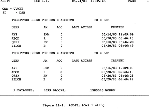
illustrative information is provided on how the OWN parameter of the AUDIT utility affects output listings.
February, 1984 - This change packet supports the COS 1.13
release. It includes editorial and technical amendments to
information which had been included in previous versions of
this manual. The contents reflect new multitasking
capabilities. Additional information has been included for
coding the CALL statement. New parameters have also been
documented in this manual for foreign dataset processing, particularly on the ASSIGN and ACCESS control statements. The LDR statement has been modified considerably; RELEASE, SAVE, MODIFY, DELETE, PERMIT, ACQUIRE and PDSLOAD also have new
parameters. Furthermore, new information is included for
Revision
M
Description
December, 1984 - This reprint with rev~s~on describes many
technical changes to COS for the 1.14 release, including contiguous disk allocation and the tape features multi tape mark, online tape ring processing, partial IBM multifile, special end-of-volume processing, and superblock size. The revision describes software to support four-processor CRAY X-MPs and systems with up to 8 million words of memory. Appendix B provides instructions for Subsystem Support: interjob communication, user channel access, and event
recall. This revision also documents the Integrated Support
Processor (ISP). Note that ISP code will be released later.
This revision contains several format changes. To increase
the accuracy of the tables and related information in appendix
A, the section is printed as generated by the system. In the
I
I
I
I
I
PREFACE
This manual describes the external features of the Cray Operating System
(COS). It is intended as a reference document for all users of COS. The
manual deals with three aspects of COS:
• Job processing. Sections 1 through 5 discuss the fundamentals of
creating and running jobs on a Cray Computer System. These
sections describe the system components, storage of information on a Cray Computer, and job processing. They also introduce COS job control and describe the use of libraries.
• Job control statements. Sections 6 through 15 describe each COS
job control statement and ,give the format of each with an explanation of its function.
• Control statement structures. Section 16 describes the control
statement block structures available with COS. Examples at the
end of the section demonstrate the COS control statement procedure sUbstitution process.
Other CRI publications that may be of interest to the reader are:
Products and
SR-OOIO SR-0013 SG-0055 SG-0056 SR-0066 SR-0073 SR-0074
Languages
SR-OOOO SR-0009 SR-0012 SR-0014 SR-0060
utilities
Software Tools Reference Manual UPDATE Reference Manual
Text Editor (TEDI) User's Guide
Symbolic Interactive Debugger (SID) User's Segment Loader (SEGLDR) Reference Manual Cray Simulator (CSIM) Reference Manual SORT Reference Manual
CAL Assembler Version 1 Reference Manual FORTRAN (CFT) Reference Manual
Macros and Opdefs Reference Manual Library Reference Manual
Pascal Reference Manual
I
Hardware
HR-OO,04 HR-0029 HR-0030 HR-0032 HR-0064 HR-0630
Miscellaneous
CRAY-l Hardware Reference Manual
CRAY-l S Series Mainframe Reference Manual CRAY I/O Subsystem Reference Manual
CRAY X-MP Series Mainframe Reference Manual CRAY-l M Series Mainframe Reference Manual
Mass Storage Subsystem Hardware Reference Manual
SR-0039 CRAY-OS Message Manual
CONTENTS
PREFACE
1.
2.
INTRODUCTION TO JOB PROCESSING
HARDWARE REQUIREMENTS • SYSTEM INITIALIZATION •
CENTRAL MEMORY ASSIGNMENT AND CHARACTERISTICS • Memory-resident COS
User area of memory
Job Table Area - JTA User field
MASS STORAGE CHARACTERISTICS MAGNETIC TAPE CHARACTERISTICS •
DATASETS
DATASET MEDIUM
MASS STORAGE DATASETS • MEMORY-RESIDENT DATASETS
INTERACTIVE DATASETS MAGNETIC TAPE DATASETS
USER TAPE END-OF-VOLUME PROCESSING TAPE MARK PROCESSING BY TQM • DATASET STRUCTURE •
Blocked format •
Blank compression • Block control word Record control word • Interactive format •
Unblocked format • Tape formats •
Interchange format Transparent format DATASET LONGEVITY •
Temporary datasets • Permanent datasets •
Magnetic tape permanent datasets Mass storage permanent datasets • LOCAL DATASETS
3.
4.
5.
DATASET DISPOSITION CODES •
USER DATASET NAMING CONVENTIONS • USER I/O INTERFACES •
COS JOB PROCESSING
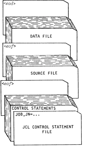
JOB DECK STRUCTURE
GENERAL DESCRIPTION OF JOB FLOW • Job entry
Job initiation • Job advancement Job termination JOB MEMORY MANAGEMENT •
Initial memory allocation
Modes of field length reduction User management of memory
Management by control statement from the run stream • Management from within a program
Management associated with a program System management of memory
JOB RERUN •
EXIT PROCESSING • REPRIEVE PROCESSING • INTERACTIVE JOB PROCESSING
JOB LOGFILE AND ACCOUNTING INFORMATION
JOB CONTROL LANGUAGE
SYNTAX VIOLATIONS • VERBS.
System verbs •
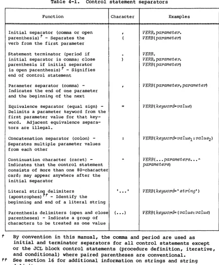
Local dataset name verbs • Library-defined verbs System dataset name verbs SEPARATORS
PARAMETERS
Positional parameters Keyword parameters •
Parameter interpretation • Conventions
LIBRARIES •
PROCEDURE LIBRARY • PROGRAM LIBRARY •
OBJECT CODE LIBRARIES •
6.
7.
JOB CONTROL STATEMENTS
. . .
.
. .
.
.
.
. .
.
JOB DEFINITION • • • • • • • • • • • • • •
DATASET DEFINITION AND CONTROL • • • •
PERMANENT DATASET MANAGEMENT • • • • •
Mass storage dataset attributes
Permission control words • • • •
.
.
.
Public access mode attribute • •
Public access tracking attribute • • • • • • •
Permits attribute • • • • •
Text attribute • • • • • • • • •
Notes attribute • • • • • • •
. .
Establishing attributes for mass storage datasets • • • •
Existing permanent dataset • • • •
New permanent dataset • • • • Attributes dataset • • • •
Protecting and accessing mass storage datasets •
Privacy • • • • • • • • • • •
Access mode • • • • • Dataset use tracking Attribute association • • DATASET STAGING CONTROL • • •
PERMANENT DATASET UTILITIES • LOCAL DATASET UTILITIES • • ANALYTICAL AIDS • • • • • • EXECUTABLE PROGRAM CREATION • OBJECT LIBRARY MANAGEMENT • •
JOB DEFINITION AND CONTROL
JOB - JOB IDENTIFICATION • • • •
MODE - SET OPERATING MODE EXIT - EXIT PROCESSING
MEMORY - REQUEST MEMORY CHANGE SWITCH - SET OR CLEAR SENSE SWITCH
* -
COMMENT STATEMENT • • • • • • •NORERUN - CONTROL DETECTION OF NONRERUNNABLE FUNCTIONS RERUN - UNCONDITIONALLY SET JOB RERUNNABILITY • • • •
IOAREA - CONTROL USER'S ACCESS TO I/O AREA • • • • •
CALL - READ CONTROL STATEMENTS FROM ALTERNATE DATASET
RETURN - RETURN CONTROL TO CALLER. • • • • • •
ACCOUNT VALIDATE USER NUMBER AND ACCOUNT
CHARGES - JOB STEP ACCOUNTING • • •
.
.
.
. .
ROLLJOB - ROLL A USER JOB TO DISK
. . . .
.
SET - CHANGE SYMBOL VALUE • • • • •
ECHO - ENABLE OR SUPPRESS LOGFILE MESSAGES
LIBRARY - LIST AND/OR CHANGE LIBRARY SEARCHLIST • OPTION - SET USER-DEFINED OPTIONS • • • • • • • •
8.
9.
DATASET DEFINITION AND CONTROL
ASSIGN - ASSIGN DATASET CHARACTERISTICS • RELEASE - RELEASE DATASET • • • • • • • INTEGRATED SUPPORT PROCESSOR (ISP) DATASETS
PERMANENT DATASET MANAGEMENT
SAVE - SAVE PERMANENT DATASET • ACCESS - ACCESS PERMANENT DATASET ADJUST - ADJUST PERMANENT DATASET • MODIFY - MODIFY PERMANENT DATASET •
DELETE - DELETE PERMANENT DATASET • • • • • • • • • • • • • • • PERMIT - EXPLICITLY CONTROL ACCESS TO DATASET • • • • • • • EXAMPLES OF PERMANENT DATASET CONTROL STATEMENTS
10. DATASET STAGING CONTROL • • • • • • • •
11.
ACQUIRE - ACQUIRE PERMANENT DATASET •
DISPOSE - DISPOSE DATASET • • • • •
SUBMIT - SUBMIT JOB DATASET FETCH - FETCH LOCAL DATASET
PERMANENT DATASET UTILITIES • • • •
PDSDUMP - DUMP PERMANENT DATASETS • PDSLOAD - LOAD PERMANENT DATASETS •
AUDIT - AUDIT PERMANENT DATASETS • • • •
12. LOCAL DATASET UTILITIES • • • •
COPYR - COpy BLOCKED RECORDS COPYF - COPY BLOCKED FILES
COPYD - COpy BLOCKED DATASET • • • •
COPYU - COPY UNBLOCKED DATASETS
SKIPR - SKIP BLOCKED RECORDS • • • • • • • •
SKIPF - SKIP BLOCKED FILES SKIPD - SKIP BLOCKED DATASET SKIPU - SKIP UNBLOCKED DATASET
REWIND - REWIND BLOCKED OR UNBLOCKED DATASET • • • • • • • • •
WRITEDS - INITIALIZE A BLOCKED RANDOM OR SEQUENTIAL DATASET
13. ANALYTICAL AIDS • • • • •
DUMPJOB - CREATE $DUMP
DEBUG - PRODUCE SYMBOLIC DUMP DSDUMP - DUMP DATASET • • • • • COMPARE - COMPARE DATASETS
PRINT - WRITE VALUE OF EXPRESSION TO LOGFILE FLODUMP - FLOW TRACE RECOVERY DUMP
FTREF - GENERATE FORTRAN REFERENCE LISTING FTREF control statement
Directives • • • • • • • SUBSET directive CHKBLK directive
CHKMOD directive • • • • •
SYSREF - GENERATE GLOBAL CROSS-REFERENCE LISTING Use of SYSREF • • • • • • • • • • • • • Global cross-reference listing format ITEMIZE - INSPECT LIBRARY DATASETS
File-level output • • • • • •
Output for binary library datasets •
14. EXECUTABLE PROGRAM CREATION •
LDR CONTROL STATEMENT • LOAD MAP
SELECTIVE LOAD
PARTIALLY RELOCATED MODULES •
Generation of re10catab1e overlays • • • • • • •
Memory layout when re10catab1e overlays exist
Memory layout of a re10catab1e overlay image • • • • •
O'VERLA.YS • • • • • • • • • • • • • • •
Overlay directives •
FILE directive • • • • • OVLDN directive •
SBCA directive
Type 1 overlay structure • • • • • • Type 1 overlay generation directives ROOT directive • • • • • • • • POVL directive • • • • • • • •
Type Type
Type Type
SOVL directive
Generation directive example • • • • • • • • • • • • 1 overlay generation rules
1 overlay execution • • • • • • FORTRAN language call • • • • •
CAL language call • • • • • • • • • • • • 2 overlay structure • •
2 overlay generation directive • • • • • • • • • OVLL directive • • • • • • • • • • • • • • • • • • •
Generation directive example • • • • • • • • •
Type 2 overlay generation rules Type 2 overlay execution •
FORTRAN language call •
CAL language call • • • • • • • Overlay generation log • • • • • • •
15. OBJECT LIBRARY MANAGEMENT •
BUILD CONTROL STATEMENT • PROGRAM MODULE NAMES PROGRAM MODULE GROUPS • PROGRAM MODULE RANGES • FILE OUTPUT SEQUENCE
FILE SEARCHING CONSIDERATIONS • BUILD DIRECTIVES
FROM directive • OMIT directive • COpy directive • LIST directive • EXAMPLES
16. JOB CONTROL LANGUAGE STRUCTURES •
CONTROL STATEMENTS
Simple control statement sequences • Conditional control statement blocks •
IF - Begin conditional block ENDIF - End condiditonal block ELSE - Define alternate condition • ELSEIF - Define alternate condition • EXITIF - Exit from conditional block Conditional block structures
Basic conditional block •
Conditional block with ELSE • Conditional block with ELSEIF • Conditional block with ELSEIF and Iterative control statement blocks •
LOOP - Begin iterative block ENDLOOP - End iterative block • EXITLOOP - End iteration
JOB CONTROL LANGUAGE EXPRESSIONS Operands •
Integer constants • Literal constants •
Operators
Symbolic variables Subexpressions
Arithmetic operators Relational operators Logical operators • Expression evaluation Strings
Literal strings • Parenthetic strings • PROCEDURES 15-1 15-1 15-3 15-4 15-4 15-4 15-5 15-5 15-6 15-6 15-7 15-8 15-9 16-1 16-1 16-1 16-2 16-2 16-2 16-3 16-3 16-4 16-5 16-5 16-6 16-7
ELSE 16-9
PROCEDURES (continued)
Complex procedures • • • • • • • • • • • • • • • • PROC - Begin procedure definition • • • • • • Prototype statement - Introduce a procedure
Procedure definition body • • • • • • • • • • • • • •
&DATA - Procedure data • • • • ENDPROC - End procedure definition Parameter substitution • • • •
positional parameters • Keyword parameters
Positional and keyword parameters Apostrophes and parentheses • • • •
APPENDIX SECTION
A.
B.
JOB USER AREA • • • •
JOB TABLE AREA - JTA
JOB COMMUNICATION BLOCK - JCB LOGICAL FILE TABLE - LFT DATASET PARAMETER AREA - DSP
PERMANENT DATASET DEFINITION TABLE - PDD BEGIN CODE EXECUTION TABLE - BGN
DATASET DEFINITION LIST DDL
OPEN DATASET NAME TABLE - ODN
OPTION TABLE - OPT • • • •
JCL BLOCK INFORMATION TABLE - JBI JCL SYMBOL TABLE - JST
LABEL DEFINITION TABLE - LDT LDT header • • • •
Volume 1 entry •
Header 1 entry •
Header 2 entry • • • • • • • • • EVENT RECALL PARAMETER BLOCK - ERPB • USER DRIVER PARAMETER BLOCK - DRPB RECEPTIVE CONTROL BLOCK - RCB • • •
NODE CONTROL BLOCK - NCB • • • • •
INTERJOB COMMUNICATION MESSAGE BUFFER MHB
INTERJOB COMMUNICATION PARAMETER BLOCK - IJPB
SUBSYSTEM SUPPORT
INTERJOB COMMUNICATION
Establishing communication
Sending and receiving messages • • • •
Closing communication paths • • • System requests • • • • • • • • USER CHANNEL ACCESS
EVENT RECALL • • • • • • • • • • • • • • • • • • • • • • • • •
C • CHARACTER SET • • • • • • • • • • • • • • • • • • • • • • • • • C-l
D. EXCHANGE PACKAGES • • • • • • • • • • • • • • • • • • • • • • • D-l
E. ERROR AND STATUS CODES
SYSTEM ERROR CODES
PERMANENT DATASET STATUS CODES
FIGURES 1-1 1-2 2-1 2-2 2-3 2-4 2-5 2-6 3-1
Cray Computer System configuration Central Memory assignment • • • Data hierarchy within a dataset • Format of a block control word
Format of a record control word • • • • • • • • •
Example of dataset control words (octal values shown) • • • • • Interchange-format tape dataset (octal values shown)
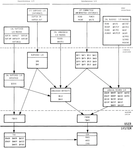
Relationship of levels of user I/O • • • •
Basic job deck • • • • • • • • •
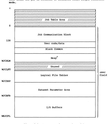
3-2 User area of memory for a job • 3-3 Example of a job logfile
11-1 PDSDUMP listing • • 11-2 PDSLOAD listing • • 11-3 AUDIT, LO=S listing
11-4 AUDIT, LO=P listing • • • • • •
11-5 AUDIT, LO=L:P:N listing • • • • • • • • •
11-6 AUDIT, LO=L listing • • • • • • •
11-7 AUDIT, LO=N Listing (AUDIT, LO=T is nearly identical)
13-1 Example of a flow trace summary • • • • • • • • • • • •
13-2 Example of a flow trace recovery dump • • • • • • • • • •
13-3 Sample listing of ITEMIZE for a PL • • • • • • • • • • • • • • 13-4 Sample listing of ITEMIZE for a binary library dataset
with X and NF parameters • • • •
14-1 Example of a load map • • • • • •
14-2 Example of Type 1 overlay loading • • 14-3 Example of the Type 2 overlay tree 14-4 Example of Type 2 overlay loading • • • 16-1 Basic conditional block structure • • 16-2 Conditional block structure including ELSE 16-3 Conditional block structure including ELSEIF
16-4 Conditional block structure including ELSE IF and ELSE • 16-5 Iterative block structure • • • • • • • • • •
16-6 Procedure definition deck structure • • • • • • • • •
FIGURES (continued)
A-I A-2 A-3 A-4
Job Communication Block (JCB) • • • • • • Logical File Table (LFT) entry
Dataset Parameter Area • • • • • • • • • CDC record format • • • • • • • • • • • •
A-5 Save areas used by asynchronous SETPOS • • • • • • •
A-6 Permanent Dataset Definition Table (PDD) • • • •
A-7 Permanent Dataset Definition Table (PDD) format 2 • • • • •
A-8 Permanent Dataset Definition Table (PDD) format 3 •
A-9 Permanent Dataset Definition Table (PDD) format 4 •
A-IO Begin Code Execution Table (BGN) • • • • • • • • • • • •
A-II Dataset Definition List (DDL) • • • • • • • • • •
A-12 Open Dataset Name Table (ODN) • • • • • • • • •
A-13 Option Table (OPT) • • • • • • • • • • • • • • •
A-14 JCL conditional block information • • • • • • • • •
A-IS JCL iterative block information • • • • • • • • • • • •
A-16 JCL Symbol Table (JST) • • • • • • • • • • • • • •
A-17 Label Definition Table (LDT) header • • • •
A-18 Header redefinition of LDDNT • • • • • • • • • • • • • •
A-19 Label Definition Table (LDT) volume 1 entry •
A-20 Beginning of VSN list • • • • • • • • • • • • • • • • A-21 Label Definition Table (LDT) header 1 entry •
A-22 Label Definition Table (LDT) header 2 entry •
A-23 Event Recall parameter block • • • • •
A-24 Channel Access parameter block • • • • • • • •
A-25 Receptive control block • • • • • • • • • • • • • • • • • •
A-26 Node control block • • • • • • • • • •
A-27 Interjob Communication Message Buffer • • • • • • • •
A-28 Interjob communication parameter block • • • • • •
B-1 A typical subsystem interjob communication structure
D-l CRAY-l Exchange Package • • • • • • • • • • • • • • • •
D-2 CRAY X-MP Exchange Package • • • • • • • • • • • • • • • •
TABLES 1-1 4-1 6-1 8-1 8-2 9-1 9-2 13-1 16-1 16-2 16-3 16-4
Physical characteristics of 200 ips, 9-track tape devices • Control statement separators • • • • • • • • •
Permanent dataset management control statements for each
medium • • • • • • • • • • • •
RS defaults for IBM tape files • • • • • •
RS restrictions for IBM tape files • • • • • • • • • •
RS defaults for IBM tape files • • • • • • •
RS restrictions for IBM tape files • • • •
DSDUMP output format • • • • • • • • •
Symbolic variable table • • • • • • •• • • •
Expression operator table • • • • • • • • • •
Keyword substitution after expansion • • • •
Expansion of parenthetic and literal string values
TABLES (continued)
A-I
E-I
E-2
Permanent dataset function codes
Error codes for reprieve processing • • PDD status • • • • • • • • • • • • • •
GLOSSARY
SUMMARY
INDEX
A-18
E-I
I
INTRODUCTION TO JOB
PROCESSING
The Cray Operating System (COS) is a multiprogramming, multiprocessing, and multitasking operating system for Cray Computer Systems. The
opepating system
provides for efficient use of system resources by monitoring and controlling the flow of work presented to the system in the form of jobs. The operating system optimizes resource usage and resolves conflicts when more than one job is in need of resources.COS is a collection of programs residing in Cray mainframe Central Memory
or on system mass storage following
staPtup
of the system. (Startup isthe process of bringing the Cray Computer System and the operating system to an operational state.)
Jobs are presented to the Cray Computer System by one or more computers
referred to as
fpont-end computeps
(also referred to asstations
inCray Research manuals). A front-end computer can be any of a variety of computer systems. Software executing on the front-end computer system is beyond the scope of this publication.
COS includes linkages providing for the initiation and control of
interactive jobs and data transfers between the Cray Computer System and front-end terminals. These features are available only where supported by the front-end system.
The FORTRAN compiler (CFT), library routines, the CAL assembler, and the UPDATE source maintenance program are described in separate publications.
HARDWARE REQUIREMENTS
The Cray Operating System (COS) executes on the basic configuration of any CRAY-l or CRAY X-MP Computer System. Each computer system contains the following components:
• One or more Central Processing Units (CPUs)
• Central Memory
• An I/O Subsystem (lOS) or a minicomputer-based Maintenance Control
Unit (MCU). The I/O Subsystem performs all required Maintenance
Control Unit functions.
I
• A Mass Storage Subsystem. The Mass Storage Subsystem consists of disk drives, an optional Solid-state Storage Device (SSD) , and lOS Buffer Memory (BMR).• An optional IBM-compatible tape subsystem. The tape subsystem
requires that an I/O Subsystem be present.
The I/O Subsystem consists of from two to four I/O processors and one-half million, one million, four million, or eight million words of
shared Buffer Memory. The optional tape subsystem is composed of at
least one block multiplexer channel, one tape controller, and two tape units. The tape units supported are IBM-compatible 9-track, 200 ips, 1600/6250 bpi devices.
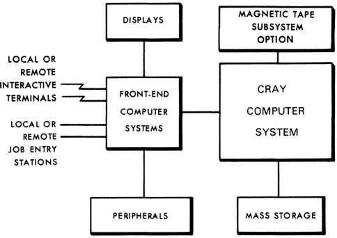
Figure 1-1 illustrates a basic system configuration. For more
information about CRAY-l or CRAY X-MP hardware characteristics, refer to the appropriate mainframe reference manual listed in the preface.
SYSTEM INITIALIZATION
COS is loaded into Central Memory and activated through a system startup
I
procedure performed at the I/O Subsystem or MCU. At startup, linkage tothe Permanent Dataset Catalog (DSC) is reestablished on mass storage. All permanent mass storage datasets are recorded in the DSC; thus, permanent datasets survive startup and the user can always assume that they are present. See section 2 of this manual for more information on datasets.
CENTRAL MEMORY ASSIGNMENT AND CHARACTERISTICS
Central Memory is shared by COS, jobs running on the Cray mainframe, dataset I/O buffers, and system tables associated with those jobs. COS allocates resources to each job, when needed, as these resources become available. As a job progresses, information is transferred between Central Memory and mass storage. These transfers can be initiated by either the job or by COS.
DISPLAYS
MAGNETIC TAPE
SUBSYSTEM
OPTION
LOCAL OR
REMOTE
INTERACTIVE
LCRAY
TERMINALS
FRONT.ENDCOMPUTER
COMPUTER
LOCAL OR SYSTEMS
SYSTEM
REMOTE JOB ENTRY STATIONS
PERIPHERALS MASS STORAGE
Figure 1-1. Cray Computer System configuration
MEMORY-RESIDENT COS
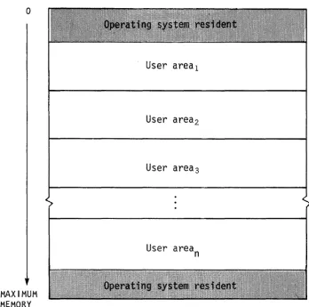
COS occupies two areas of Central Memory. The memory-resident portion of
the operating system occupying lower memory consists of Exchange
Packages, the System Executive (EXEC), the System Task Processor (STP),
and optionally the Control Statement Processor (CSP). The
memory-resident portion of the operating system occupying extreme upper memory contains station I/O buffers, space for the system log buffer, and
[image:23.613.65.549.109.451.2]o
MAXIMUM
MEMORY
User areal
User area2
User area3
User area
n
Figure 1-2. Central Memory assignment
USER AREA OF MEMORY
COS assigns every job a user apea in Central Memory. The user area
consists of a Job Table Area (JTA) and a user field.
Job Table Area - JTA
For each job, the operating system maintains an area in memory that contains the parameters and information required for monitoring and
managing the job. This area is called the Job Table Area (JTA). Each
active job has a separate Job Table Area adjacent to the job's user
[image:24.615.116.464.61.406.2]I
I
User field
The
user fieLd
for a job is a block of memory immediately following thejob's JTA. The user field is always a multiple of 512 words. The
beginning or
Base Address
(BA) and the end orLimit Address
(LA) areset by the operating system. The maximum user field size is specified by a parameter on one of the job control statements (see section 6) or by installation-defined default. A user can request changes in user field size during the course of a job.
Compilers, assemblers, system utility programs, and user programs are loaded from mass storage into the user field and are executed in response to control statements in the job deck. Each load and execution of a
program is referred to as a
job
step.A detailed description of the contents of the user field is given in section 3 of this manual. Briefly, however, the first 200a words of the user field are reserved for an operating system/job communication
area known as the Job Communication Block (JCB). Programs are loaded
starting at BA+200a and reside in the lower portion of the user field. The upper portion of the user field contains tables and dataset I/O
buffers. The user field addressing limit is equal to
LA-I.
Memory addresses for instructions and operands are relative to BA. The
Cray mainframe adds the contents of BA to the address specified by a memory reference instruction to form an absolute address. A user cannot reference memory outside of the user field as defined by the BA and LA
register contents; LA-I is the user limit. (Refer to the appropriate
mainframe hardware reference manual noted in the preface for more information.)
MASS STORAGE CHARACTERISTICS
All information maintained on mass storage by the Cray Operating System (except specific pre-allocated areas such as the Device Label) is
organized into quantities of inform~tion known as
datasets.
Ingeneral, the user need not be concerned with the physical transfer of data between the disks and memory nor with the exact location and physical form in which datasets are maintained on mass storage. COS translates the user's logical requests for data input and output into disk controller functions automatically.
Each disk storage unit contains a device label, datasets, and unused
space to be allocated to datasets. The
device LabeL
notes usable andunusable (unflawed and flawed) space on the disk unit and designates one
of the devices as the Master Device. The
Master Device
is the diskstorage unit containing a table known as the
Dataset CataLog
(DSC),To the user, mass storage
pePmanent datasets
are always present and available on mass storage. This permanence is achieved throughtechniques permitting the datasets noted in the DSC to be recovered or reestablished in the event of system failures. Portions of COS, such as the loader, utility programs, the compiler, the assembler, and library maintenance and generation routines, reside in permanent datasets accessible by user jobs at any time.
Datasets containing job input decks and output from jobs also reside on mass storage. Because these datasets are listed in the Dataset Catalog they are also regarded as permanent. This designation is somewhat
misleading since their permanence is by definition rather than by tenure in the system. That is, the input dataset is permanent from the time it is staged from the front-end system to the Cray Computer System until the job terminates. Output datasets being disposed to a front end are
permanent from job termination (or whenever the disposition was
initiated) until the disposition is complete. The permanence of these system-defined datasets allows them to be recovered along with other permanent datasets after a system failure.
Any user job can create a mass storage permanent dataset. It can be subsequently accessed, modified, or deleted by any other job having correct access privileges and producing the correct permission control words when attempting to associate it with the job. Permission control words are defined at the time the dataset is designated as permanent
(that is,
saved).
A permanent dataset ceases to be permanent when a user with the correct permission control word deletes it. This deletion notifies COS that the space occupied by the dataset is no longer permanent. However, the space is still reserved by the dataset until it is released by the user (see sections 8 and 10, respectively, for information on the RELEASE and DISPOSE control statements).
In addition to the various permanent datasets, mass storage is used for temporary datasets. A
tempoPQPy dataset
is created by the job using it and remains temporary unless it is designated as permanent, released, or disposed to a front end by the job. A temporary dataset neither saved as permanent nor disposed of is termed ascpatch dataset
and ceases toexist when the job releases it or terminates.
MAGNETIC TAPE CHARACTERISTICS
An I/O Subsystem can include an Auxiliary I/O Processor (XIOP) with the capability of addressing up to 16 block multiplexer channels of tape units. Each block multiplexer channel can be attached to IBM-compatible control units and tape units in a variety of configurations. The block multiplexer channels communicate with the control units and tape units to allow reading and writing data that can also be read and written on
IBM-compatible CPUs. The physical characteristics of tape devices are
summarized in table 1-1. The block sizes in this table are used by the COS tape system for transparent-format tape datasets (described in section 2).
Density (bits/inch)
6250 1600
Table 1-1. Physical characteristics of 200 ips, 9-track tape devices
Transfer rate Data/2400 ft. Percent of
(kilobytes/sec) reel (megabytes) reel
con-taining data
1170 168 94
300 43 94
Block size (bytes)
DATASETS
Nearly all information maintained by the Cray Operating System (COS) is
organized into quantities of information known as
datasets.
Thefollowing are some of the more important factors to remember about datasets.
• The dataset
medium
is the type of physical device on which thedataset resides.
• The dataset
structupe
is the logical organization of the dataset.• The dataset
longevity
is the retention period for the dataset.• A dataset must be
local
to be usable.• The dataset
disposition code
tells the operating system whataction to take when the dataset is no longer local.
• Each dataset is known by its
dataset name.
• Datasets are read and written using operating system requests
(user I/O interfaces).
DATASET MEDIUM
Datasets can be classified by medium, as follows:
• Mass storage datasets
• Memory-resident datasets
• Interactive datasets
• Magnetic tape datasets
MASS STORAGE DATASETS
2
MEMORY-RESIDENT DATASETS
Some datasets can be specified by the user as memory-resident datasets. A
memopy-pesident dataset
is wholly contained within one buffer (see BS parameter on the ASSIGN control statement in section 8 of this manual) and remains in memory at all times. Such a dataset ordinarily occupies no mass storage. A memory-resident dataset is normally a temporarydataset; however, a mass storage permanent dataset can be declared memory resident.
A dataset can be declared memory resident to reduce the number of I/O requests and disk blocks transferred. Memory residence is particularly useful for intermediate datasets not intended to be saved or disposed to another mainframe. All I/O performed on a memory-resident dataset takes place in the dataset buffers in memory and the contents of the buffers are not ordinarily written to mass storage. Such a dataset cannot be made permanent, nor may it be disposed to another mainframe, unless copied to mass storage.
Normally, a memory-resident dataset is empty until written on. If an existing dataset is declared memory resident, it is loaded when the first
read occurs. A user attempting to write to a memory-resident dataset must have write permission. However, as long as the buffer does not appear full, no actual write to mass storage ever occurs. Therefore, changes made to an existing dataset declared memory resident are not
reflected on the mass storage copy of the dataset.
A memory-resident dataset must be defined through an ASSIGN control statement containing the MR parameter or through an F$DNT call to the system. If the F$DNT call is used, the Dataset Definition List (DDL) supplied should specify DDMR=I. (See the description of the ASSIGN control statement in section 8 of this manual.) In addition, the buffer size parameter should specify a buffer large enough to contain the entire dataset plus one block.
If at any time the system I/O routines are called to write to the dataset and the buffer appears to be full, the dataset ceases to be treated as memory resident, the buffer is flushed to mass storage, and all
memory-resident indicators for the dataset are cleared.
Magnetic tape, execute-only, and interactive datasets cannot be declared memory resident.
INTERACTIVE DATASETS
I
Instead, records are transmitted to and from a terminal attached to a front-end station. Record positioning (for example, REWIND or BACKSPACE) is not possible.
Interactive datasets can be created by interactive jobs through the use of the ASSIGN control statement or F$DNT system call.
MAGNETIC TAPE DATASETS
A
magnetic tape dataset
is available to any job declaring tape resource requirements on the JOB statement and specifying the appropriateinformation on its ACCESS request.
To gain access to an existing tape dataset for reading and/or rewriting, the correct file identifier (permanent dataset name), the desired device type, and, optionally, a volume identifier list must be specified. The volume identifier list can consist of I to 255 volume identifiers. If
the permanent dataset name (PDN) is omitted from the ACCESS request, the local dataset name is used as the file identifier.
To gain access to a tape dataset for creating, the file identifier, desired device type, and the NEW parameter option must be specified on
the ACCESS request. If no file identifier is present, the local dataset
name is used. If the volume identifier list is missing from the access
request, it is called a
non-specific volume allocation.
Aspecific
volume allocation
occurs when the volume identifier list is present at the time of the access request. New tape datasets must be written to before a read is allowed.Other options describing the tape dataset are available from the access request. See the ACCESS control statement description (section 9 of this manual) for more details. Using other parameter options allows more efficient tape dataset descriptions.
COS automatically switches volumes during dataset processing unless user EOV processing is requested, and returns to the first volume of a
multivolume dataset in response to a REWIND command. If a permanent
write error occurs when trying to write a tape block for the user, COS automatically attempts to close the current volume and continues to the next volume.
The COS tape system uses Buffer Memory as a tape block buffering area so that the job's I/O buffer need not be as large as the tape block (as with other operating systems). This technique can result in significant
memory savings whenever large tape blocks are being processed and in increased transfer rates whenever smaller blocks are being processed. The advantage in having a large COS buffer is a reduction in the overhead
USER TAPE END-OF-VOLUME PROCESSING
The user tape end-of-volume (EOV) feature allows the user to gain control at tape end of volume and perform special EOV and BOV processing. The
macros used are SETSP, STARTSP, ENDSP, TAPES TAT and CLOSEV. These macros
are used on individual datasets. If EOV processing is needed for more
than one dataset, the macros must be issued for each tape dataset. Refer to CRI publication SR-OOI2, Macros and Opdefs Reference Manual for more information.
The user instructs the system to perform EOV processing by issuing the
SETSP macro (with the ON option) after a tape dataset is opened. Using
SETSP with the OFF option informs the system that EOV processing is no
longer needed. The CLOSE macro also terminates EOV special processing.
To test that the tape dataset is at EOV, you must use the TAPESTAT macro
after every READ, WRITE, and SYNCH macro. Not all macros that result in
I/O operations return EOV status7 for example, the CLOSE, POSITION, and REWIND macros do not return EOV status. For output datasets, the user should use the SYNCH macro to flush the buffers and check to see if EOV has been encountered before using such macros.
After EOV is encountered, the user starts EOV processing by issuing the
STARTSP macro. During EOV processing the user may do read, write, and
position operations. Volume switching is done by issuing the CLOSEV macro. When EOV processing is completed, the ENDSP macro notifies the system to return to normal processing.
During EOV processing, no read ahead is performed. Data blocks are read one at a time. Also, a position request with relative block number is positioned from the current tape position, not from the last I/O block.
For an output dataset, the data in the lOP buffer when EOV is encountered is considered part of the dataset and may be read during EOV processing. Once the data is read, it is no longer part of output data. Because no read ahead is performed during EOV processing, the program may position
backwards and read only the blocks on the tape. If this is the case, the
data in the lOP buffer is written to tape when the ENDSP macro is issued.
The use of the CLOSEV macro is not restricted to the EOV routine. The CLOSEV macro may be issued by the user anytime during dataset
processing. This macro allows the user to terminate an output tape
anywhere and continue the dataset on the next tape. It also allows the
user to read part of a tape and switch to the following tape.
TAPE MARK PROCESSING BY TQM
continue processing after its occurrence is detected. The label types are specified on the ACCESS statement and allow processing of field ANSI labels (FAL), field standard IBM labels (FSL) , and field nonlabeled (FNL) tapes.
When TQM recognizes a tape mark in the data, it translates it to an EOF record control word and puts it in the data. The user gets a tape mark indication when processing the data using the TAPESTAT macro and then is able to continue normal processing. The recognition of end-of-file conditions is the responsibility of the user.
To keep the program from running off the end of the tape on reads, the software stops processing (that is, no reading ahead occurs) when a tape mark is detected and does not move forward until the user catches up to
the tape position, recognizes the tape mark, and issues further read commands.
Any attempt to position past a tape mark (using the POSITION macro) results in the tape moving until the tape mark is encountered. At that point, tape movement stops and the user job gets control. A residual record count is returned to find the position on tape. The tape is physically positioned after the tape mark just encountered.
For input, all field format tapes (FAL/FNL/FSL) are processed for labels in the same way. At BOT, if a label is encountered it is validated based
on its type. If no label is found, there is no validation. When a
tapemark is detected, the system checks the next record for a EOVI or EOFI trailer label. If EOVI is found, the system performs an automatic
volume switch. If an EOFI is found, the system performs end-of-data
processing. If neither EOVI or EOFI is encountered, the tape is left
positioned immediately following the tape mark ready for the next read. Tapes not terminated with either SL or AL standard labels must be
terminated by the program using CLOSE or CLOSEV system calls.
For output, field format tapes are labeled based on the LB parameter on the ACCESS statement. End-of-volume labels are processed when either the EOT reflective marker is sensed or when the user program calls the CLOSEV routine. End-of-file labels are written when the dataset is closed, rewound, or released.
DATASET STRUCTURE
COS supports several dataset structures:
• Blocked format
• Interactive format
• Unblocked format
BLOCKED FORMAT
Blocked format is used by default for external types of datasets, such as user input and output datasets. Record positioning requires a blocked
format. The blocked format adds control words to the data to allow for
processing of variable-length records and to allow for delimiting of levels of data within a dataset. A blocked dataset can be composed of one or more files, which are, in turn, composed of one or more records. Figure 2-1 illustrates the data hierarchy within a dataset.
Dataset
Record
2Figure 2-1. Data hierarchy within a dataset
The data in a blocked dataset can be coded and/or binary. Blanks are normally compressed in blocked coded datasets. Each block consists of
512 words. Blocked datasets use two types of control words: block and
record.
Blank compression
Blank fields can be compressed for blocked coded files. Blank field compression is indicated by a blank field initiator code followed by a count. The default blank field initiator code is defined by the
installation parameter I@BFI which is either an ASCII code or 7778 indicating that blank compression will not be done. Blank compression can be inhibited using an ASSIGN statement parameter or an F$DNT system
call. A blank field of 3 through 96 characters is compressed to a
2-character field. The count is biased by 3681 the actual character
I
I
Block control word
The block control word (BCW) is the first word of every 5l2-word block. The format of a block control word is depicted in figure 2-2.
Field
M
BDF
BN
FWI
o
4 11 31 54 55 63MI////////I 1/////////////////1 BN I FWI
BDF
Figure 2-2. Format of a block control word
Bits
0-3
11
31-54
55-63
Description
Type of control word (for block control word,
M=O)
Bad Data flag; indicates the following data, up to the next control word, is bad. This flag is set by the I/O Subsystem for magnetic tape datasets in interchange format.
Block number. Designates the number of the
current data block. The first block in a dataset is block O.
Forward index. Designates the number of words
(starting with 0) to the next record control
word or block control word.
Record control word
A record control word (RCW) occurs at the end of each record, file, or dataset. The format of a record control word is illustrated in figure
2-3.
4 39 40 54 55 63
MI
Field
M
PFI PRI I FWI
Figure 2-3. Format of a record control word
Bits
0-3
Description
[image:35.612.73.519.68.714.2]Field Bits
UBC 4-9
TRAN 10
BDF 11
I
SRS 12PFI 20-39
PRI 40-54
FWI 55-63
Description
Unused bit count. For end-of-record, UBC designates the number of unused low-order bits in the last data word of the record terminated by the end-of-record. For end-of-file and
end-of-data ROWs, this field is O. The data
area protected by UBC must be zero-filled.
Transparent record field; used for an
interactive output dataset only. If set,
sUbstitution of end-of-record ROWs is suppressed.
Bad Data flag; indicates the following data, up to the next control word, is bad. This flag is set by the I/O Subsystem for magnetic tape
datasets in interchange format. If flag is set,
an irrecoverable error was encountered in following data.
Skip remainder of sector; indicates that the next control word to follow is a BOW and the data after this ROW is not to be processed. This is used only in tape dataset processing.
Previous file index. This field contains an index modulo 220 (20,000,0008) to the beginning of the file. The index is relative to the current block such that if the beginning of the file is in the same block as this ROW, the PFI is
o.
Previous record (ROW) index. This field
contains an index modulo 215 (100,0008) to the block where the current record starts. The
index is relative to the current block such that if the first word of data in this record is in
the same block as this ROW, PRI is
o.
Forward word index. This field points to the next control word (ROW or BOW) and consists of a count of the number of data words up to the control word (that is, if the next word is an
Disregarding block control words occurring at 5l2-word intervals in a dataset, RCWs have the following logical relationship in a dataset.
An end-of-record RCW immediately follows the data for the record it
terminates. If the record is null, that is, if it contains no data, an
end-of-record RCW can immediately follow an end-of-record or end-of-file RCW or can be the first word of the dataset.
An end-of-file RCW immediately follows the end-of-record RCW for the
final record in a file. If the file is null, that is, if it contains no
records, the end-of-file ROW can immediately follow an end-of-file RCW or can be the first word of the dataset.
An end-of-data RCW immediately follows the end-of-file RCW for the final
file in the dataset. If the dataset is null, the end-of-data RCW can be the first word on the dataset.
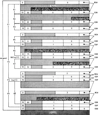
The typical dataset has many end-of-record RCWs per block. An example of
dataset control words is illustrated in figure 2-4. In this example, a
dataset is contained within four physical sectors, each beginning with a BCW (thus the four BCWs in this example are numbered 0, 1, 2, 3). The
dataset contains four files shown as Fl, F2, F3, and F4. Fl contains the
four records shown as Rl through R4J F2 contains records R5 through R7J F3 contains no records at all; F4 contains record R8.
INTERACTIVE FORMAT
Interactive format closely resembles blocked format; however, each buffer
begins with a block 0 BCW. Each record transmitted to or from COS by an
F$RDC or an F$WDC call must contain a single record consisting of a BCW, data, and an end-of-record RCW.
Two formats for interactive output can be assigned when the dataset is created: character blocked and transparent. Character blocked mode is
the default. In character blocked mode, an end-of-record RCW is
interpreted as a line feed or a carriage return. In transparent mode,
the end-of-record RCW is ignored and the user is responsible for supplying carriage control characters.
UNBLOCKED FORMAT
Fl
Dataset
F2
R6(null)
I
R7
L
Figure 2-4. Example of dataset control words
(octal values shown)
Bew
EOR
EOR
EOR
Bew
EOR [OF
EOR EOR
EOR
BeW
EOF EOF
Bew
[image:38.612.103.527.73.550.2]I
The system does not allocate buffers in the job's I/O buffer area for unblocked datasets; the user must specify an area for data transfer. When a read or write is performed on an unblocked dataset, the data goes directly to or from the user data area without passing through an I/O buffer. The word count of data to be transferred must be a multiple of 512.
Unblocked I/O cannot be performed on an interchange format tape dataset.
TAPE FORMATS
Tape datasets are written and read on tape volumes. A
tape volume
is areel of tape. A tape volume is also known as a dataset section (for example, in FSEC= on the ACCESS statement).
Data is read or written in tape blocks. A
tape blook
is a unit of datarecorded on magnetic tape between two consecutive interblock gaps. The size of tape blocks can vary from one byte to an installation-defined maximum.
Tape datasets can be read or written using two different formats:
intepohange
ortPanspapent.
Tape datasets can also be labeled or unlabeled.Interchange format
Interchange format facilitates reading and writing tapes that are also to
be read or written on other vendors' systems. In
intepohange format,
each tape block of data corresponds to a single logical record in COS blocked format (that is, the data between record control words).
In interchange format, tape block lengths can vary up to an
installation-defined maximum which cannot exceed 1,048,576 bytes (131,072
64-bit words). It is recommended that the maximum block size not exceed
100 to 200 kilobytes. Blocks exceeding these sizes may require special operational procedures (such as the use of specially prepared tape
volumes having an extended length of tape following the end-of-tape (EOT) reflective marker) and yield little increase in transfer rates or storage capacity.
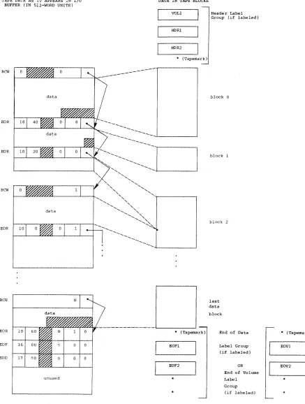
When a tape dataset is read in interchange mode, physical tape blocks are represented in the user's I/O buffer with block control words (BCWs) and
record control words (RCWs) added by COS. The data in each tape block is
terminated by anRCW. The unused bit count field in the RCW indicates
the amount of data in the last word of the tape block that is not valid data. A BCW is inserted before every 511 words of data, including the
RCWs. The formats of RCWs and BCWs are described previously in this