gramming language that supports graphics. More recently, interactive graphics editors have be-come commonplace. Graphics editors are easy to use but lack many of the capabilities found in graphics programming languages. This deficiency is intrinsic to graphics editors; it is not a result of neglect or incompetence by the implementer.
Tweedle is a graphics editor that attempts to bridge this gap by using a program as its internal representation for a picture. During an editing session the user can modify either the picture itself or the program representation; the editor modifies the other to keep the two consistent. The language used by the editor contains features that allow the editor to incrementally execute parts ofa program in response to a change so that the picture can be regenerated without completely reexecuting the program.
The use of a procedural representation allows the user to create pictures with structure, repeti-tion, recursion, and calculated point values. It further allowshim to define parts of a drawing as variants of other parts; these variants can differ from their original objects in quite arbitrary ways but still respond to changes made to the original. The language supports linking different parts of the picture together to maintain connections between parts as the picture changes.
A working prototype of Tweedle has been implemented under the X Window System.
1.1. Overview
1.2. Graphics languages and graphics editors
1.3. Procedural and nonprocedural representation languages 1.4. What Tweedle isn't
1.5. A note on the cast of characters 2. Previous Work
2.1. Procedural representations in graphics systems 2.2. Graphics editors
3. The Programming Language 3.1. Language design goals 3.2. Language overview
3.2.1. Graphics operations 3.3. Object semantics
3.4. Why a new language? 4. The Graphics Editor
4.1. Incremental execution 4.2. User interface
4.2.1. Bounding boxes 4.3. Generating code 4.4. An extended example 5. Implementation
5.1. Overview 5.2. Parsing
5.3. Data representation 5.4. Basic execution
5.5. Paths and the display tree 5.6. Objects and inheritance 5.7. Display and funargs 5.8. The usingstatement 5.9. Incremental parsing 5.10. Incremental execution 5.11. Display and graphics editor 5.12. Display optimization
5.12.1. Display coordinate caching
5.12.2. Incremental bounding box calculations 5.12.3. Incremental redisplay
5.13. Relative transformations 5.14. Source-code optimization 5.15. Libraries
5.16. Generating PostScript 6. Contributions and Future Work
6.1. Contributions
6.2. Deficiencies&future work 6.3. What I would do differently I. Syntax of the Dum Language II. Predefined Functions
II.I. Mathematical functions
II.2. Comparison and logical functions
II.3. Point manipulation functions II.4. Transformation functions II.5. Array manipulation functions II.6. String functions
II.7. Paint functions II.8. Object functions
85 85
People have used computers to create pictures nearly as long as computers have existed. These pictures range from crude character graphics on a line printer to the sophisticated output of today's laser printers. Traditionally, people created these pictures by writing a program in some computer language that supported graphics, usually through some kind of subroutine library. In-teractive drawing programs, or graphics editors, are an alternate way of creating pictures, and in the past decade these editors have gone from being an interesting novelty to an accepted part of computer systems. Each approach has advantages and disadvantages, and in many cases these are complementary: the disadvantages of programs are the advantages of editors, and the dis-advantages of editors are the dis-advantages of programs.
My goal is to integrate these two approaches by creating a graphics editor that uses a program as the underlying representation for a picture. This allows a user to use the editor to interactively create pictures while still having the capability to fall back upon programming when necessary.
1.1.
Overview
Tweedle is a system that combines a graphics editor, Dee, with a programming language, Dum. Any graphics editor must use some kind of data representation to store the picture inter-nally during execution and exterinter-nally between executions; in Dee this representation is a program written in the Dum language. Executing the program produces the picture.
Dee presents the user with two windows, one containing a picture to be edited and the other containing the text of the program that represents the picture. The user can change the picture by selecting parts ofitwith a mouse and issuing commands through menus, or can change the text using a standard text editing interface. Changes to the picture are reflected immediately by cor-responding changes to the program so that the modified program will produce the modified pic-ture; changes to the text take place in the picture when a Do Changes operation is selected.
Tweedle contains several innovative ideas. Most important, it extends procedural represen-tations into the domain of interactive programs. Up to now, procedural representations have been batch oriented; programs that used them manipulated them as a whole. In Tweedle, the representation is constantly changing in response to user input, and acceptable interactive response precludes fully reexecuting the representation in response to every change. Tweedle's interpreter is able to incrementally execute changed representations, executing only a subset of the program but producing the same results as if the program had been fully reexecuted. The interpreter automatically determines how much of the program is affected by a program change; in order to make this work well, Dum was designed to allow this determination be done through a static structural analysis of the program.
Dum programs are structured by defining and calling drawing procedures that create subparts of a picture. These subparts, called objects, can later be manipulated by the program in order to change the picture. Dum thus combines the simplicity of the drawing procedure approach with the flexibility of the segment approach to graphics languages.
object will also affect the variant. Variant objects make it easy for a user to create different objects with a similar style and to keep these objects consistent should the style change.
Objects in Dum can define control points that other object can use for positioning. Control points can allow arrows to connect to boxes, captions to be centered under pictures, or, since control points are gravity active in the editor, objects to line up on a grid. The interpreter ensures that whenever an objectis changed that allparts of the program that depend upon the values of the object's control points are properly reexecuted so that the positioning relationships continue to hold.
1.2. Graphics languages and graphics editors
Graphics editors are one type of "what you see is what you get", orWYSIWYG,program. The picture on the screen directly reflects the picture in the final output, and changes to the picture take place as soon as they are specified by the user. These editors are easy to use and quite sufficient for many pictures; however, they have some limitations. Because the editor is con-strained to show exactly the current picture, structuring information is either invisible to the user or simply not present at all. Frequently different parts of the picture should bear some spatial relationship to each other, and unless these relations are explicitly described somewhere they are likely not to hold as the parts of the picture are moved around. Some pictures require points with exact or computed values, and these are difficult to create with an editor. Other pictures are most easily expressed using iteration or recursion, facilities absent in graphics editors.
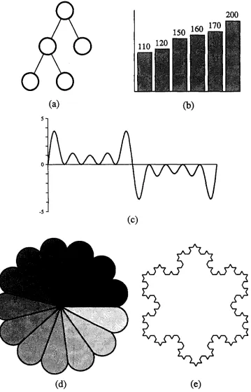
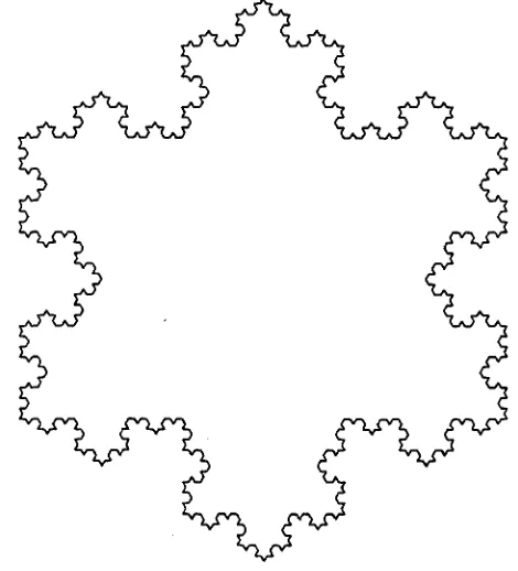
Figure 1-1 shows some examples of pictures difficult to create with a traditional graphics editor. The binary tree, Figure 1-1a, contains a great deal of structuring information not evident in the picture. Ifone node gets moved, its children should perhaps also move; the lines connect-ing the nodes should defmitely move; and even the points at which the lines connect to the nodes should change so that the lines continue to be directed to the center of the nodes. Figure I-Ib shows a bar graph in which the heights of the bars should correspond to some given values. In most editors the user would be forced to just make a guess at the appropriate heights. The graph in Figure I-Ie requires iteration and computation; few people would even be tempted to use a graphics editor for this. Figure I-Id's rosette uses computation both to divide the circle into thirteen equal parts and to determine the appropriate gray scale value for each segment and also uses iteration to construct and place each segment. The snowflake fractal, Figure I-Ie, is most easily created using recursion to draw each side.
A different problem arises when dealing with collections of pictures. Books and papers often contain many illustrations, and the author usually wants them all to have the same style. Some-times that style will change, requiring, perhaps, bolder lines or a different style of arrows. Using a graphics editor to change each picture can be very tedious. Many of the shortcomings of graphics editors are discussed by Jon Bentley in his article "Little Languages" [8].
(a)
(b)
(c)
[image:7.618.146.505.49.609.2](d)
(e)
Languages are not, however, without their own problems. The overhead involved in writing even a simple program can be daunting. Interactive behavior must be specifically coded into each program; without it getting the desired output can be a tedious repetitive cycle of editing, compiling, running, and looking at the output. The flip side of allowing exact point values is requiring them, even when the programmer has only a vague idea of what they might be.
These problems most often show up in positioning. It is easy to write a program that draws a tree, but difficult to place the nodes for a pleasing result without interactive feedback. Drawing a graph or plot is easy; finding the best place for titles and legends is not. Freehand drawing and layout require user interaction to prevent total frustration.
Tweedle combines the ease of use of a graphics editor with the completeness and extensibility of a graphics language; the limitations of graphics editors are overcome by giving the user the full power of a language for writing extensions, structuring pictures, and specifying exact or computed values. The editor can manipulate user-defined objects like the five pictures in Figure 1-1 as easily as it can manipulate predefined objects like lines, circles, and rectangles. Both are represented as procedures that use low-level graphics primitives to do drawing; the only dif-ference is that the defmitions of predefmed objects are implicitly included in each drawing. Users can store their own objects in libraries and thereby make them available to multiple draw-ings, so it is easy to maintain consistency across drawings.
Of course Tweedle does not require its user to use the language to define new objects; in many cases the new objects can be created within the editor by combining already existing objects. Most of the time the user can use the editor without caring that his picture is represented as a program, but when he encounters the limits of the editor he can edit the program representation instead. A given picture can combine objects created by the graphics editor and objects created by the text editor indiscriminately.
1.3. Procedural and nonprocedural representation languages
Computers rarely operate upon real world entities; instead they manipulate representations of these entities. Arepresentation is a well-defined data structure that maps properties of these real entities to computer-operable information. A language is a set of rules that defines which data structures form valid representations. The distinction between languages and representations is largely artificial, and which term is used frequently depends upon the scale of the problem. When the rules describing the data structure are simple, as with a binary tree representing a sorted list, one usually focuses on the data structure itself and calls it a representation. When the rules are complex, as with a stream of characters representing an algorithm, one focuses on the rules instead and calls it a language.
Arguments about whether procedural or nonprocedural languages are most appropriate for a problem have been going on for quite some time [22]. Nonprocedural languages allow the program writer to concentrate upon the end result without worrying about implementation details. This makes them easier to use, especially for nonprogrammers. Conversely, the lan-guage implementor is free to use whatever means are most appropriate to a particular implemen-tation to achieve these results.
The most severe limitation of declarative languages is that they do not extend gracefully. As long as the user is trying to describe the kinds of things the designer envisioned when he created the language, there are no problems, but as soon as he tries to do anything else he finds himself in trouble. Ifthe language cannot describe it, the user cannot write it; this is sometimes called "running into the edges of the representation." Some nonprocedural languages solve this by allowing extensions to the language, but the language used for the extensions is usually quite different from the original language.
Procedural languages can solve the extensibility problem by having low level primitives and control structures for combining them; however, these primitive operations can make it easy for the user of such a language to become enmeshed in a web of details irrelevant to the problem he is trying to solve. Most procedural representation languages have facilities for defming macros or procedures that represent high level constructs; programs that uses these are often indistin-guishable from descriptive programs. Procedural languages can thus masquerade as declarative ones, but not vice-versa.
Procedurality, it must be noted, does not automatically guarantee extensibility. Command stream languages consist of a series of operations and are thus procedural, but they do not have the ability to compose these operations in an extendible way. Early text formatting programs provide a good example of this. In order to format an indented quotation, a user would write something equivalent to
Skip a line
Set left margin to 2 inches Set right margin to 6.5 inches
Format the text "This is the body of the quotation" Set left margin to 1 inch .
Set right margin to 7.5 inches Skip a line
(The "Fonnat the text ... command would normally be implicit). Page description languages can be similar: "Move to (500,654). Switch to italics. Print an 'A.' " Extensible procedural languages contain commands similar to these in order to actually produce results, but they allow the commands to be grouped into subroutines, used in conditionals and loops, and take cal-culated values as arguments. [34] I will hereafter use "procedural" to refer only to languages with these properties, and "command" to refer to procedural languages without them.
Scribe [30,31,32] is a document description language that is almost entirely declarative. The bulk of an input file consists of sections of text enclosed in environments that describe the func-tion or appearance of the text they enclose. Typical functional environments are quotations, footnotes, subscripts, and enumerated lists; appearance environments can indicate centering, italics, and so forth. Scribe also contains a few procedural constructs like starting a new page or setting tab stops.
TEX [17,18] and troff [28] are procedural document description languages. They contain commands to do things like change margins, skip vertical space, and change type faces, and also contain commands that manipulate esoteric things like registers, parameters, marks, insertions, diversions, and traps. Neither raw TEX nor raw troff is a particularly hospitable environment for anyone but the most dedicated hacker; fortunately both provide macro facilities that allow the messy details to be hidden from the casual user.
LATEX [20] is a popular macro package for TEX. A document written using U\TEX doesn't look much different from one written using Scribe; for example, in U\TEX one writes a quotation like
\begin{quotation}
This is an uninteresting quote. \end{quotation}
while in Scribe one writes
@begin(quotation)
And this one isn't much better. @end(quotation)
The actions taken by the document compiler are, however, very different in each case. In U\TEX the \begin {quotation} and the \end {quotation} get expanded as macros into series of low-level TEX commands; these commands skip the appropriate space above and below and change the margins. In Scribe, @begin (quotation) causes a database lookup to find the attributes of the quotation environment. This lookup tells the compiler that the quotation's text should be offset with vertical space above and below and should have narrower margins. The difference is subtle but important. The definition of a U\TEX macro can contain arbitrarily complicated TEX commands such as conditional expressions, mathematical computations, or recursive macro calls. The definition of a Scribe environment, on the other hand, gives the set-tings of predefined text parameters. A TEX user can produce novel layout effects by including new macro definitions in his input file; in Scribe these could only be produced by modifying the compiler to add new features.
This distinction is intrinsic to representation languages for any sufficiently complex system. There will always be things that require computation to represent cleanly, and any language that includes computation is, by definition, procedural. Any particular feature can be added to a declarative language by extending the language definition, of course, but before long the lan-guage starts to lose any coherence it originally had. Descriptive lanlan-guages excel at well-defined, closed tasks, while procedural languages are needed when the job is open-ended.
<
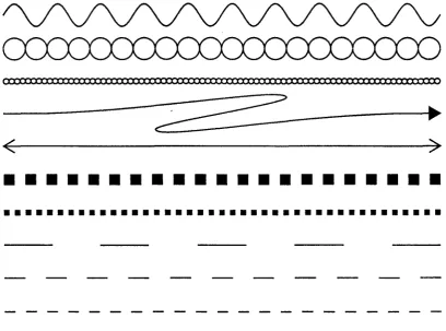
Figure 1-2 shows some of the flexibility gained by this approach. Each line is an instantiation of a different object. Each object definition takes two points as arguments; what it does to get from one point to the other varies from object to object. Computation allows the objects to slightly modify the circle, square, or dash size in order to assure that the space gets filled with an integral number of elements.
~.a:Ca:rrx::rJ:J:X1X
---~---I~
)
•••••••••••••••••••••
•••••••••••••••••••••••••••••••••••••••••
Figure1-2: Sample line styles programmable within Tweedle
1.4. What Tweedle isn't
This particular implementation of Tweedle is not a production quality graphics editor; its goal was to be demonstrative, not comprehensive. Many things have been left out, and many simplifying assumptions have been made. The implementation is, however, quite usable: except for occasional screen dumps showing Dee in operation, all the illustrations in this thesis were drawn withDee.
1.5. A note on the cast of characters
2. Previous Work
2.1. Procedural representations in graphics
systems
Procedural graphics representations can be generally divided into two classes: segment-based representations and display procedure representations. Segment-based representations include such popular standards as Core and GKS [37, 38]. These representations contain explicit graphi-cal objects, usually graphi-called
segments
orsymbols,
that are identified by name and are manipulated by predefined operations. A program first creates a segment, then adds primitive objects like lines and curves to it. When the segment is complete, the program closes it and then explicitly draws the segment on the display. A program mayor may not be able to modify an existing segment once it has been closed. The structure of the program that manipulates the segments is entirely independent of the structure of the picture; this makes segment-based representations well-suited for applications that changethe picture based on user interaction.In a display procedure representation, subparts of the picture are represented by procedures that draw them. The main program consists of a series of procedure calls, and when the program has finished running, the picture is complete. Procedure-based representations are conceptually simple but they are poorly suited to many interactive applications since the program must be changed and reexecuted in order to change the picture. Their big advantage is flexibility: a segment can be rotated, scaled, or otherwise transformed but otherwise always looks the same, while a procedure can alter its flow of execution to produce different results depending upon its input arguments, the current graphics state, or global style parameters [25].
This last feature turns out to be very important for computer flight simulation, which requires rapid rendering of a constantly changing image. This image will typically contain many small distant objects and only a few large close ones. The close objects must be rendered in detail to obtain realism, and the distant objects must be rendered quickly to obtain the needed speed. Dis-play procedures are ideal for this application since they can readily adapt their output to show a . level of detail appropriate to their size in the image.
In this environment John Gaffney and John Warnock produced the Evans and Sutherland Design System [14]. This language combined the image model used in other Evans and Suther-land systems with a simple stack-based semantic model. Although the Design System has never been described in the literature, it had an enormous impact upon later work. John Warnock moved to Xerox PARC and together with Martin Newell created an interactive graphics system called JaM [41]. JaM combined the Design System's execution model with a slightly different graphical model.
Several years later, work began at PARC to develop a successor to Xerox's page description language, Press [27]. Press was a device-independent representation that had been implemented on various raster printers and achieved widespread use in the academic community; however, it had a very limited set of graphical capabilities. JaM became the base for this successor, Interpress [42]. During this time Chuck Geschke and John Warnock left PARC to form Adobe Systems and there they designed the PostScript language [1], also based upon JaM.!.
These languages are all more similar than they are different. Each is a stack oriented token based language; a program consists of a series of operands to push upon the execution stack and operators that act upon them. Certain operators allow the definition of new operators while others provide graphic operations, arithmetic functions, control structures, and so forth. Programs in these languages structure their pictures by defining and calling drawing procedures.
Special purpose graphics languages are designed to represent a particular class of drawings. Most of these are too limited in scope to be interesting, but one, PIC, provides an interestingmix
of descriptive and procedural operations [15, 16]. PIC addresses itself to the boxes-and-arrows illustrations so common to technical writing. It contains primitive operations like box, circle, ellipse, and arrow. A typical PIC program consists of a series of invocations of these operators:
ellipse "PIC" "source" arrow
box "PIC" arrow
ellipse "TROFF" "code"
This would produce a picture similar to Figure 2-1. The PIC interpreter takes care of the spacing between boxes, the positioning of labels, and other similarly menial tasks. Its defaults can be overridden by supplying extra arguments to the operators, and the interpreter accepts arguments in a wide variety of syntaxes, for example
arrow right from 1/3 of the way between last box.ne and last box.se
The ".ne" and ".se" in this example function similarly to control points in Tweedle but are restricted to a small set of predefined values. In addition to high level operations like "box" and "ellipse," PIC supplies a full set of procedural operations likefor and
if.
A user can define macros, but these are treated quite differently from the built-in operations. PIC is very good at boxes-and-arrows pictures but can be difficult to use in other situations.@
source~
PIC@
codeFigure 2-1: PIC sample output
2.2. Graphics editors
I define aneditor as a program that allows a person to interactively edit the representation of some object. A useful distinction can be drawn between internal and external representations: an internal representation is how the editor stores the object while working on it, and an external representation is how the editor stores the object between executions. Most editors use external representations that are just versions of the internal representation capable of being stored on a file system; unless otherwise mentioned this is true of all editors discussed here.
Particularly interesting are editors that constantly present the user with an image of the current state of the object being edited; these are called "what you see is what you get", or WYSIWYG
editors.e There are three main classes of WYSIWYG editors, each requiring successively more abstract representations: text editors, document editors, and graphics editors.
WYSIWYG text editors are sometimes just called screen editors. Typical of these are the various implementations of Emacs [39, 13]. The representation being manipulated in text editors is really just the text me itself.
Document editors provide the same type of formatting as the document description languages discussed in the last chapter. A section of the current document is displayed upon the screen and the user manipulates it by chosing sections of text and altering such attributes as font, size, mar-gins, and line spacing. Bravo [21] was one of the earliest examples of a document editor. It was actually "what you see is almost what you get" since the screen size and available resolution precluded showing a full page's width of characters: a document's line breaks on the screen occurred at different places from those in the printed output. Document editors are now com-monplace, a typical example being MacWrite [4]. Their representation for the document is generally some form of command language with corrunands to change the text attributes inter-spersed with the text of the document. '
Since it is impossible to store a picture as such in a computer, a graphics editor's represen-tation must be more abstract than the others'. Some graphics editors, often called paint programs, use bitmaps as representations; among these are Markup [26], a pioneering effort, and MacPaint [3]. Bitmaps have three main disadvantages as representations, size, nonportability, and lack of structure. A bitmap representation's size is proportional to the size and not the com-plexity of the image; this is an advantage only for very small or extremely complicated images. Bitmap images cannot take advantage of the improved resolution of most printers; lines, curves, and letters will be printed at the screen resolution rather than the printer resolution. Bitmaps are also very difficult to scale by other than an integral amount and to rotate by other than multiples of ninety degrees. The general transformation algorithms are slow and the results are usually disappointing. Perhaps the most severe limitation is the lack of structure. While paint programs have commands to add lines, rectangles, or circles to the picture, once these things have been added they are just bits in the bitmap. It is impossible to later operate upon these objects as themselves; the user can only manipulate the bits that make up the objects.
Most graphics editors use some sort of static hierarchical data structure to represent the pic-ture. The image is kept as a list of picture items, each of which is either a primitive item or another list. One of the first such editors was Draw from Xerox PARe [7]; MacDraw is a popular current example [5]. These editors frequently feature grids to help users make accurate drawings; grids force points in the image to coincide with points in a rectangular grid. Grids can help in many cases, but even such a simple image as an equilateral triangle is beyond their capabilities.
Some editors gain some additional power by using an external representation that is human readable. Inthese systems the user can use a standard text editor to achieve results that would be impossible or tedious in the graphics editor. Bell Labs' PED [29] is one such system.
rectangle the user would first define four points A, B, C, and D in approximately the right posi-tions, draw the line segments AB, BC, CD, and DA, and then place the following constraints on the points:
AB is parallel to CD
AB is the same length as CD AC is the same length as BD
(Other sets of constraints are possible.) The first constraint forces the quadrilateral ABCD to be a trapezoid, the second forces it to be a parallelogram, and the third forces it tobea rectangle by making the diagonals equal in length.
Constraints have many attractive features. Standard numerical analysis algorithms can be used to resolve them. They represent the types of relations common in drawings in a natural, consistent fashion. Finally the interface to constraint systems is straightforward: the user uses a pointing device to select points in the picture and chooses a constraint from a menu to apply to these points.
These advantages are countered by some serious problems. Getting the constraints right for a picture can be a difficult task roughly equivalent to trying to draw the picture using a compass and straightedge. The constraint solver satisfies the constraints by moving points in the picture; care must be taken to assure that it does not move the wrong points. Similarly, a given set of constraints can have many solutions. In the rectangle example, above, the constraints would be solved by
any
rectangle; the editor must provide some way of making sure that the solver produces the one the user had in mind. A combinatorial explosion occurs as more and more constraints are added requiring mutual satisfaction, so the user must carefully structure his pic-ture hierarchically to allow the solver to limit itself to just a few constraints at one time. Unless the editor allows the user to define his own constraints, some pictures will be tedious or even impossible to draw. Without user-definable constraints, it is usually impossible to constrain line segments to have a particular length, angles to have particular values, or distances to have a calculated relation to each other. This makes pictures like the bar graph and equation plot in Figure 1-1 intractable. As in other declarative systems, iteration, recursion, and computation are only awkwardly expressed.The first constraint system was Ivan Sutherland's seminal Sketchpad [40]. Sketchpad stored constraints as functions that return how far their arguments are from satisfying the constraint; the constraint solver varied the arguments until all the error terms became zero. As an example, the procedure for a constraint forcing two points to behorizontal might return the absolute value of the difference of the points' x coordinates. New constraints types could only be added by modifying the editor. Although primitive by today's standards (it had, for example, no curves, and constraints were selected by flipping switches on the front panel of the computer) Sketchpad provided nearly all the features found in graphics editors today.
midpoint := (pointl + point2) / 2 OR point2 := pointl + 2 * (midpoint - pointl) OR pointl := point2 + 2 * (midpoint - point2)
Here the interpreter has the choice of three different methods to use for satisfaction. The order-ing of the methods indicates that the solver should first try to satisfy the constraint by assigning midpoint; if that fails it should attempt to assign point2, and if that fails it should attempt to assign pointl.
Although not usually considered a graphics editor, METAFONT [17,19] by Don Knuth can be used as such. In a METAFONT session the user explicitly adds, modifies, and deletes constraints on named points in the picture. METAFONT's interface is strictly textual, and the user can defme his own constraints.
Juno [24], by Greg Nelson, is perhaps Tweedle's closest relative. A Juno picture is represented as a program in the Juno language, and the user can interactively edit either the pic-ture or the program. Juno differs from Tweedle in that its language is very restrictive. A state-ment in Juno takes the form of a guarded command:
LET variables I constraints IN commands END
This introduces a set of point variables (all variables in Juno represent points), forces their values to satisfy the constraints, and uses them in the commands. The commands can contain drawing commands like fill and stroke as well as additional guarded commands. The variables in the outer guarded command are available within the inner, but their values cannot be changed by the constraint solver. Juno has a very limited set of constraints, and they may not be extended. It attempts to find the "right" solution to multiply-valued constraints by allowing an initial guess of the value; the solver starts with this guess as its solution and tries to satisfy the con-straints by moving the points as little as possible. The guess starts out as the actual position of an input point, and, after the constraints have been solved, it is replaced by the actual value found for the point. This allows subsequent solutions to be found very quickly.
Daedalus [6] is a VLSI editor that uses constraints to represent the spatial relationships of the components. The layout is represented as a LISP program, and the user is able to change either the picture or the program. Only a small set of predefmed constraints are available.
The CMU Tutor system [35, 36] is similar in some ways to Juno and to Tweedle. This is a programming environment designed to assist people in producing computer assisted instruction programs. CMU Tutor shows simultaneously the program to produce the current page of the CAl program and the present state of the current page. A graphics editor for the current page generates the source code required to produce the desired output; changes to the current page are incrementally compiled by the system. The level of editing available is quite primitive; the CMU Tutor editor allows the user to add objects easily, but once they are added they can only be modified by selecting sections of code and giving new values to the points included therein.
3. The Programming Language
In normal use, the Dum programming language appears to play a subordinate role to the Dee editor. The user is creating a drawing, not writing a program, and so can, for the most part, ignore the language except in the rare occasions that he needs to edit the text. This view is a carefully cultivated illusion; the true relationship is just the opposite.
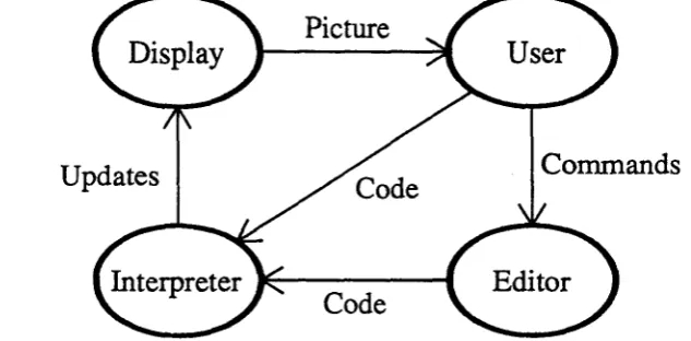
[image:19.621.149.466.227.383.2]Dee's internal structure looks more like a programming environment than a graphics editor. When the user performs some editor operation, the editor alters the program so that it will produce the required change, then incrementally executes the program to update the picture (Figure 3-1). It is therefore important to understand the language in order to understand the editor.
Updates
Picture
Code
Commands
Figure 3-1: The flow of information during an editing session
Conversely, the Dum language must be considered in the context of the editor in order to understand its design. The program text is constantly being changed, both by the editor and by the user, so the language should be simple to parse and to interpret. Furthermore, the amount of work done in response to a program change should be proportional to the size of the change, not to the size of the program. Finally the language must have constructions analogous to the opera-tions of the graphics editor in order for the variation hierarchy to exist.
3.1. Language design goals
The most basic goal in Dum was to have it be based upon standard imperative programming language features. Other systems, notably Juno [24] showed that a multiple-view editor is pos-sible by using an unconventional language; the goal in Tweedle was to make it work using a conventional one so as to make it as easy to program as possible. Dum should contain variables, functions, iteration, alternation, and so forth.
It is generally acceptable for a major change to a picture to require several seconds to take place, but small, common changes like adding, moving, or deleting objects must take place quickly. This is achieved in Tweedle through incremental execution, the ability to selectively execute parts of the program so that the picture appears as it would had the entire program been reexecuted in response to the change. Doing this efficiently requires avoiding language con-structs that allow the execution of one part of a program to make state changes that would affect the results of unrelated parts of a program, so many important features of Dum programs can be discovered through static semantic analysis of the program text.
The object variation hierarchy allows one object to be defined as a variant of another. This mechanism is quite general: a variant object can add, delete, move, or change the subparts of the original object. The variant is described by the list of changes done to the original to make it into the variant; therefore Dum needs a means to describe all these types of changes.
3.2. Language overview
The syntax of Dum superficially resembles that of LISp:3 a program is a series of lists whose elements are either atoms or other lists. This syntax iseasy to parse, and the resulting parse tree is very easy to manipulate. Dum is, however, not an applicative language since its lists
are
frequently just convenient ways of grouping together similar items and of delimiting statements.
Dum's types are sununarized in table 3-2. Numbers are either integers or floating point and are converted from one to the other as required. They are also used as boolean values with zero representing false and any other value representing true. Points are pairs of numbers; they are just a convenient method of keeping (x,y) pairs together. Strings are immutable but can be of any length. Arrays are dynamic collections indexed by integers with no restrictions placed upon the types of the individual elements. A paint describes something that can be used to draw with; in the current implementation they are restricted to shades of gray but could also represent colors or fill patterns. Object variables are used to refer to subparts of the picture and will be discussed fully in section 3.3.
Datatype number
point string array paint object
Sample constants
2 3.14 -4el0
[0 0 ] [ 1 0 0 - 1 0 0 ] [ 1 1 • 5 ]
"hello, world" "" "nice new rattle" none
none none
Figure3-2: Basic types in Durn
Expressions are written exactly as in LISP: the operation name is followed by the arguments. Each argument is evaluated and the operation is called with the resulting values. Point expres-sions occur so frequently that there is a bit of syntactic sugar to represent them: [x y] is shor-thand for (makepoint x y). Here are some sample expressions:
17
[(* r (cos theta» (* r (sin theta»] (sqrt (+ (* x x) (* y y)))
(concat (translate [100 100]) (rotate 45»
Dum contains most of the features found in any ALGOL-like language; It Just uses more parentheses to express them than usual. A program can contain if,for, while, begin, and assign-ment stateassign-ments. Variables must be defined before they are used; however, data definition state-ments can be freely mixed with executable code. Since arrays can contain values of different types, all type-checking in assignments and routine calls is done at runtime.
There are two types of subroutines in Dum, functions and object definitions. Object defini-tions can, to a first approximation, be thought of as funcdefini-tions that return objects. Two features guarantee that subroutines act as strict mathematical functions: arguments are always passed by value, and no non-local references are allowed. Since there are no side effects, a change in a subroutine can only affect those parts of the program that use the subroutine's value. This locality allows the incremental execution mechanism to bound the amount of the program that needs to be reexecuted in response to a change. Furthermore, the behavior of a subroutine is totally specified by its parameters, so the interpreter can call subroutines without worrying about the global context.
An example of a function defmition may help to make the syntax more concrete. Consider the following absolute value function:
(function abs
(returns number) (args (number i» (method
(if « i 0)
( : = abs (neg i))
(:= abs i )
)
This declares a function abs. Abs takes one argument, a number, and returns a number. The method clause contains the body of the code, which in this case is a single
if
statement. The first sublist of theif
statement is the condition, the second is the true branch, and the third is the false branch. In this case the function assigns either -i or i to abs, depending upon whether or noti is less than zero.
Dum provides a full set of predefmed functions for arithmetic, trigonometry, graphical trans-formations, point manipulation, and assorted other uses; these are described in Appendix
n.
Two functions that are worth noting at this point since they will be used frequently in examples are grayscale, which returns a paint representing a particular shade of gray, and arr,which returns an array containing its arguments. Programs can also include libraries of functions and object definitions; these allow sets of programs to create consistent sets of drawings easily.3.2.1. Graphics operations
which use Bezier cubics, Dum paths use a single point to specify curved segments and rely upon other points in the path to condition the curve. This was done primarily out of expediency: the X Window System that was used to implementDeeonly supports simple splines [12].
Dum programs produce graphical output by executing drawpath and fillpatb statements. These are compound statements; within them path construction statements define the path to be drawn or filled. Options such as the line width and the fill paint are specified as part of the statement. Ifa path contains another path, the options of the subpath override those of the main path for the duration of the subpath and the main path's options are restored when the subpath is over. Paths can also contain objects, to be discussed fully in the next section.
Graphical transformations are represented as six-element arrays and are provided by various built-in functions. The available transformations are summarized in Figure 3-3; standard graphics texts contain a full discussion of transformations and matrices [11, 25]. The current coordinate system is modified using the with statement, which takes a transformation followed by statements to execute with that transformation, After the end of the with statement the coor-dinate system is restored to what it was before.
Dum function
(translate [x y)
(scale [x y)
(rotate a)
(concat A B)
Matrix form
[
1 0 0]
0 1 0
x Y 1
[
x 0 0]
0 y 0
0 0 1
[ cos a
-sina 0]
sm a cos a 0
0 0 1
B·A
Array representation
[lOx 0 1 y]
[x 0 0 0 y 0]
[cos a sin a 0 -sin a cos a 0]
Figure 3-3: Summary of transformations in Dum
When one with statement is nested within another, the inner with is done relative to the outer. These transformations are performed in the order in which they are encountered, and modify the global coordinate system. For example, the code fragment
(with (translate [100 100]) (with (rotate 45)
... draw picture ...
)
The current transformation, the current path, and the current values of the path options collec-tively determine the graphic state of an executing program. These can only be changed by the with, drawpath, and jillpath statements, and allrevert to their previous values upon the comple-tion of the controlling statment. Changes to the graphic state are thus statically limited by program constructs, so it is possible for the interpreter to save the state at the time of some sub-routine execution and to restore it should the subsub-routine need to be reexecuted at a later time. Unrelated parts of the program cannot affect the state, so the interpreter can know that the saved state is still correct.
The current graphic state is quite invisible to program execution since there are no functions that query it. This has both advantages and disadvantages. Operations that query the global state are really just global variables in disguise; were they included, subroutines would no longer be mathematical functions. Different invocations with the same arguments might yield different results. On the other hand, the current system lacks adaptability. One advantage of procedurality is that objects can modify their appearance based upon their context, showing more or less detail, for example, depending upon their size. This ability is lost since there is no way for the object to determine what the current transformation actually is.
3.3. Object semantics
The object is the central mechanism in Dum for structuring pictures and inDeefor controlling incremental execution. Objects represent distinct manipulable portions of the drawing, and are thus somewhat similar to segments in Core or GKS [37, 38]. More concretely, an object is a binding of a path with a transformation to place the path in the picture. Ifan object represents a piece of text, a character string and a font replace the path.
It is important to keep distinct several related concepts involving objects. An object definition is a section of code that defines the appearance and behavior of an object. An object instance, also called an instantiation or simply an object, is the above mentioned path and transformation pair. The type of an object is its definition; two objects are of the same type if they are both instantiations of the same object definition, An object reference is a pointer to an object, and an object variable is a variable that holds an object reference. Object references can also be stored in arrays, so anywhere an object variable is required an array element can also be used.
An object can contain other objects as parts; a component part is called a subobject and the containing object the parent object.
..
[image:24.621.187.486.117.287.2]This separation of object creation and object drawing arises because there are times when a program needs to defer drawing. Filled objects are opaque, and objects drawn later obscure objects already on the display. Furthermore, certain positioning information about an object is available to the program whether the object has been drawn or not.
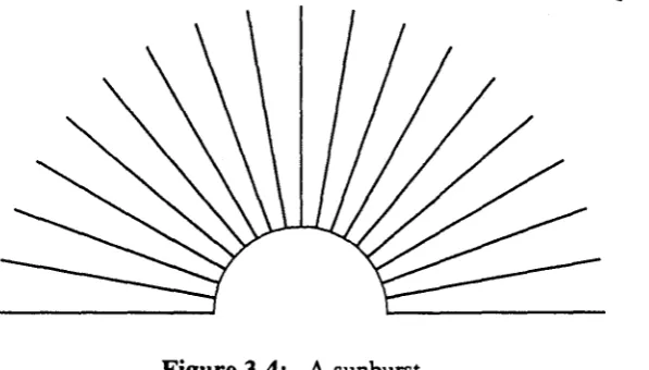
Figure 3-4: A sunburst
The center of a circle is one example of this positioning information, and it was used to create the sunburst in Figure 3-4. This picture was made by creating an opaque circle but not drawing it, then using the center of the circle to position the outward radiating lines. The circle was then drawn, covering the center portions of the lines.
The positioning information takes the form ofcontrol points,point values defined within an object definition but accessible outside. The control points for a rectangle object might be the four comers, the centers of the sides, and the center of the rectangle. The primary uses for con-trol points are to specify points that other objects can use for aligrunent and to specify which points will be gravity active in the editor. The first use is the most common and allows, for example, arrows to point to sides of boxes, captions to center themselves, and, in the above sun-burst example, the radiating lines to use the center of the circle as an endpoint. The effect of gravity will be described in the chapter on the Dee editor.
Within an object definition a control point acts just like any local point variable. Outside, the program obtains its value by using the getpoint operation, (getpoint <object reference> <control point name». Getpointis not a function since its second ar-gument is not a normal value. The value of a getpoint operation is the value assigned to the control point within the object definition, transformed by the object's transformation, and then inversely transformed by the current transformation. For example, consider the code shown in Figure 3-5. Here, the object circle has defined the control point centerand assigned it the value [0 0] in its definition. The main program instantiates a circle with a translation of (100,100) and calls it a circle. It then changes the coordinate system to a translation of (250,100) and draws a line from (0,0) to the center of a _ circle.4 (0,0) in the new translated coordinate system becomes (250,100) in device coordinates. The value of the control point must be the value that, when transformed by the current transformation, will yield the center of the
circle; so the value of the control point, (0,0),istransformed by the transformation of the object, (translate [100 100]), to give the point (100,100) in device coordinates; this value is then transformed by the inverse of the current transformation to yield the value (-150,0), which is the value of the control point.
(defineobject circle (args (number radius» (control center) (method
(:= center [0 0]) (drawpath
(arc center radius 0 360)
t one argument, the radius
t defines the control point
t the center is the origin
t draw a path that is
t an arc from 0-360 degrees
(function main (method
(with (translate [100 100]) (object a circle (circle 50») (draw a_circle)
t translate to (100,100)
t create a circle
t and draw i t )
(with (translate [250 100l) (drawpath
(moveto [0 0]) (using a circle
(lineto (getpoint a
t t
t t
circle
translate to (250,100) and draw a line from
(0,0)
to a circle's center center) )
(250,100)
Figure3-5: Sample code illustrating control points
Dum contains five statements that modify already existing objects, delete, raise, lower, transform and recall. Deleteremoves a drawn object from the display. Raise and lowerchange an object's stacking order, that is, the way in which it obscures other objects with which it over-laps. Transform changes the transformation associated with the object, causing it to appear in a different location. Recall replaces an object with a different object, and will be discussed in detail later.
may be created within afor or whileloop, and the appropriate modification in this case is dif-ficult todiscover.P More important, these statements allow the object variation hierarchy to exist.
In the object variation hierarchy, one object is defined to be a variant of another; these objects are called the variant and the originalobjects. The definition of a variant object is a list of operations to perform on the original in order to change it into the variant. These operations can include adding new subobjects, moving around existing subobjects, or even replacing these sub-objects with others. When the interpreter is called upon to execute the defmition of a variant object, it first executes the code of the original object and then, using the same values for all
local variables, executes the code of the variant. The variant can thereby use the values of any variables in the original. A variant takes the same argument list as its original, followed option-ally by some additional parameters.
This variation mechanism is very powerful, since it allows the variants to follow later changes made to the original. As long as all the variables that the variant depends upon are defined the variant will continue to make sense; if they are not, a runtime error occurs. An additional advan-tage of variants is that they inherit the control points of the original object. A node in a graph could define itself as a variant circle and thereby inherit whatever control points have already been defined for circle.
Figures 3-6 and 3-7 show an example of the variation mechanism. The object defined in Figure 3-6 draws a label centered in an oval; this was used in various figures throughout this thesis. It consists of two subobjects, a scaled circle to generate the oval and a Iabel.6 The variant object is the same except that itshows two lines of text in the oval. The original line of text is moved to a new position, and then the new second argument is used to generate the second line of text. Since the two-line module is a variant object, changes to the original like alterting the line width or using a different font will automatically apply to the variant.
The transformation of an object is bound when the object is created, not when the object is drawn. The most important reason for this is to assure that an object's control points have values, even though the object itself has not yet been drawn. A second reason is that some structured types of drawings may want to pass objects to other objects and have them drawn there. This is best illustrated by an example.
Figure 3-8 show a program to draw a binary tree. The main program creates all the nodes, placing them as it wishes. The structure of the tree is built by passing to each tree the two trees it should use as its left and right subtrees. The code that defines the tree creates a node for itself, draws connecting lines to the subtrees, draws the subtrees.f and finally draws its own node. The main program has only to draw the final tree and the entire structure appears. Since the transfor-mations are bound at creation time, the code for the tree need not worry about positioning the two subtrees.
SPar causes fewer problems since the index variable can be tested; while loops are virtually impossible.
&rhe exact arguments to thecircleobject are irrelevant here.
(defineobject module (args (string legend»
(control left right top bottom ne nw se sw center) (method
(with (scale [1.5 1])
(object oval (circle [1 25] 2» (draw oval)
)
(number f (getfont "times" 14» (number w (strwidth legend f»
(with (translate [(* -0.5 w) -5]) (object the label (text legend f» (draw the_label)
# code omitted that assigns the control points
Figure 3-6: A labelled oval
(defineobject 2 line module (variant module) (args (string-line2»
(method
(transform the label (translate [(* -0.5 w) 2]» (:= w (strwidth line2 fl)
(with (translate [(* -0.5 w) -13]) (object 2nd label (text line2 f» (draw 2nd_label)
Figure 3-7: A variant with two lines of text
The editor can change an object's transformation either by changing the transformation in ef-fect at the object's creation or by adding a transform statement to the end of the program. Whichever method is used, the editor then has the job of making sure the picture looks as if the object had always been in its new location. Simply moving the object is not enough; since the calculation of a control point's value includes its object's transformation, the values of the object's control points change. Ifthe picture is to remain consistent, all parts of the program whose results depend upon the values of these control points mustbereexecuted.
(defineobject tree
(args (object left right» t left and right subtrees (control center)
(method
t the node is a filled circle, centered at the origin,
t through the point [25 0], line width 2, fill paint white (object node (filled_circle [25 0] 2 (grayscale 1»)
t my center is the circle's center (:= center (getpoint node center»
t if there is a left subtree, connect to i t and draw i t (if (not (null left»
(begin
(using left (drawpath
(moveto [0 0])
(lineto (getpoint left center»
)
(draw left)
t ditto for right (if (not (null right»
(begin
(using right (drawpath
(moveto [0 0])
(lineto (getpoint right center» )
(draw right)
t finally draw myself (draw node)
(function main (method
t create the nodes
(with (translate [50 25])
(object treel (tree (nullobj) (nullobj»» (with (translate [150 25])
(object tree2 (tree (nullobj) (nullobj»» (with (translate [100 125])
(object tree3 (tree treel tree2») (with (translate [200 125])
(object tree4 (tree (nullobj) (nullobj»» (with (translate [150 225])
(object tree5 (tree tree3 tree4»)
[image:28.612.88.528.45.671.2]t finally draw the whole tree (draw tree5)
useful; for example, a program might want to test an object's position, and, depending whether the object is above or below a particular point, draw an arrow to the bottom or the top of the object.
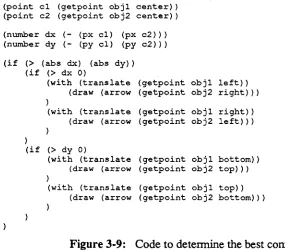
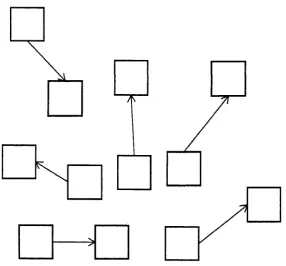
Figure 3-9 shows an example of the flexibility gained this way. This code computes the rela-tive positions of obj 1 and obj2 and determines the best way to connect them: the left edge of obj 1 to the right edge of obj 2, the right edge of obj1 to the left edge of obj2, the bottom edge ofobj 1 to the top edge ofobj 2, or the top edge of obj 1 to the bottom edge ofobj 2. It first calculates thex andy displacements between the centers of the objects, and determines the best connection by comparing their magnitudes and signs. If the x displacement is larger in magnitude than they displacement, ob j2 is closer to being to the left or right ofobj 1 than it is to being above or below it, and either a left-right or right-left connection is appropriate depend-ing upon the sign of the x displacement. Figure 3-10 shows several connections generated this way. Whenever either of the objects moves, the entire section of code needs reexecution.
(point c1 (getpoint obj1 center» (point c2 (getpoint obj2 center» (number dx (- (px c1) (px c2») (number dy (- (py c1) (py c2»)
(if (> (abs dx) (abs dy) (if (> dx 0)
(with (translate (getpoint obj1 left) ) (draw (arrow (getpoint obj2 right» ) )
(with (translate (getpoint obj1 right) ) (draw (arrow (getpoint obj2 left) ) )
)
(if (> dy 0)
(with (translate (getpoint objl bottom» (draw (arrow (getpoint obj2 top») )
[image:29.620.92.377.264.514.2](with (translate (getpoint objl top» (draw (arrow (getpoint obj2 bottom»)
Figure 3-9: Code to determine the best connection strategy
Examples like this can be detected automatically only through dynamic dependency analysis. In keeping with the goal of using static mechanisms whenever possible, Dum instead contains a language construct to indicate the relevant portions of the program. All sections of code that depend upon the location of an object must be enclosed within a using statement, (using <object reference> <code». A using statement has no immediate effect on the ex-ecution of the program; it just informs the interpreter to store the code within it as something that needs execution if the using'sobject is transformed.
I
1r---1
I
[image:30.613.183.470.49.315.2]1'\
Figure 3-10: Several connections using this scheme
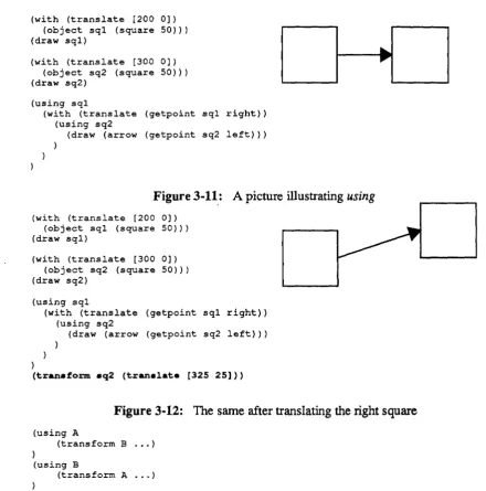
When an object gets moved, all the using statements for it get reexecuted. Figures 3-11 and 3-12 show this in action. The picture in Figure 3-11 is composed of two squares with an arrow connecting the right side if the first square with the left side of the second square. The defmition of arrow, not shown, draws an arrow from (0,0) to the point passed to it as an argument. Here, the arrow is translated to the right side of the first box and passed the left side of the second box as an argument. Since the translation involves a control point, the entire with statement must be wrapped in a using statement for the first box. Inside the with, the invocation of the arrow is wrapped within another using since it uses another control point. In Figure 3-12 a transform statement has been added that changes the position of the right square. Since the arrow invoca-tion is wrapped in a using for that square the invocation is reexecuted, this time with the new value for the control point, and the arrow continues to be attached correctly. Ifthe left box were moved instead, the interpreter would reexecuted the entire with statement. This example was fully generated by the Dee editor and illustrates its correct insertion of using statements.
Ifthe object was passed any objects as arguments, all the using statements in it for objects that were passed as parameters also must be reexecuted. The calculation of a control point's value involves both the current transformation and the transformation of the object whose control point is being used. When an object is transformed, the current transformation changes for all using statements inside its definition, so these using statements must be reexecuted.
(with (translate [200 0]) (object sql (square 50») (draw sql)
(with (translate [300 0]) (object sq2 (square 50») (draw sq2)
(using sql
(with (translate (getpoint sql right» (using sq2
(draw (arrow (getpoint sq2 left»)
I
I ,
I
Figure 3-11: Apicture illustrating
using
(with (translate [200 0]) (object sql (square 50») (draw sql)
{with (translate [300 0]) (object sq2 (square 50») (draw sq2)
(using sql
(with (translate (getpoint sql right» (using sq2
(draw (arrow (getpoint sq2 left»)
)
(tranaform aq2 (tranalate [325 25]»
Figure 3-12: The same after translating the right square
(using A
(transform B ... )
)
(using B
(transform A ... )
To avoid this problem transform statements are illegal within
using
statements and any at-tempt to execute one results in a runtime error. This is more restrictive thanitneeds to be, since it disallows many perfectly safe transformations; the interpreter could maintain a list of objects whoseusing
statements are currently being reexecuted, check any object being transformed against this list, and only signal an error if a loop should occur. [image:31.624.70.511.58.504.2]Frequently in editing one subobject in an object gets replaced by a new object which fills the same role in the picture. Dee allows its user to change the type of a particular instance of an object into a new type so that the object can be edited separately from other instances or to change the fill pattern or line width of an instantiation. These changes cannot be reflected in the program by simply using a delete statement and a new invocation because using statements in the parent object for the old subobject should now apply to the new subobject. Dum contains the recallstatement to handle these cases. Recall takes an object reference and an object invocation, (recall <old reference> <object invocation», and assigns the result of the invocation to the reference after deleting the reference's object from the picture. In addition, any using statements for the original object are reassigned to the new object. Runtime errors can occur if the new object does not define all the control points of the old object.
(defineobject underlined label (args . (string s ) -(method
(object lab (label 12 "times" s» (draw lab)
(point u [0 (using lab
(drawpath (moveto (lineto
3]) t underline offset (p+ (getpoint lab left) u» {p+ (getpoint lab right)
u»
Figure3-13: An underlined label
Underlined Label
(defineobject larger underlined label (variant underlined label) -(method
-(recall lab (label 18 "times" s»
Underlined Label
Figure3-14: A variant with larger text
For a practical example of how this is useful, consider Figures 3-13 and 3-14. Figure 3-13 defines an object that draws an underlined label; it first draws the label then draws the line under it. The variant object in Figure 3-14 has replaced the label with an one in a larger font. In order for the underline to continue to be correct, the control points used to draw it must apply to the new label instead of the old one, and this is precisely what recall does.
time and space as a function of the maximum recursion depth; without new it would require exponential time and space.
Figure 3-15: A picture with a high degree of repetition
Using new is completely transparent; the new object appears and behaves exactly as it would have had it resulted from a call to the appropriate object definition. If the arguments to the object being new'ed contain any object references, the new function actually does call the ap-propriate definition. This is because the object being called presumably uses some of the control points of the passed object, and the relation between the called object and the passed object will be different in the two cases. This is also completely transparent; the program can always call new with impugnity.
This path sharing among different instances of an object places some restrictions upon the way transformations are stored in an object. Inparticular, the transformations of subobjects must be stored relative to the transformation of their parent object. Using relative transformations has the additional benefit that when objects are moved, the editor need not update the transformations of subobjects. When drawing, a transformation stack is maintained so that local coordinates Can be mapped into global coordinates.
One unfortunate side effect of using relative transformations arises when an object is drawn by an object other than the one that created it; this occurs in the binary tree example on page 24.
[image:33.617.191.426.95.354.2]3.4. Why a new language?
One question not yet addressed is whether or not a new language is actually necessary. Would another language serve equally well? One likely candidate is PostScript [1], a language, like Durn, explicitly designed to represent images. PostScript is especially attractive since many programs produce it as output, and being able to interactively edit these files would be a valuable tool. Although Dum and PostScript share some parts of their imaging models, there are some fundamental differences that make PostScript unsuitable as an interactive representation. A review of Dum's language design goals will show how Dum satisfies these goals and why other languages, particularly PostScript, do not.
The first goal is conventionality. Dum contains all the features commonly found in standard imperative programming languages: variables, arrays, functions, assignments, for and while loops, and
if
statements. PostScript also has these features; their syntax and underlying seman-tics may be unusual but the features themselves are not.Another goal is simplicity, and both Dum and PostScript succeed here. A Dum program isa sequence of lists containing other lists and atoms, while a PostScript program is just a sequence of stack-based operations and their operands. The need for simplicity is the primary thing that keeps other languages from being appropriate.
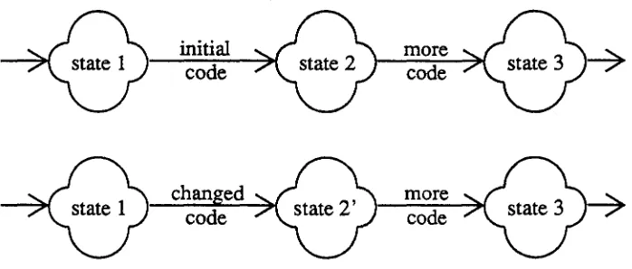
The biggest difference between Dum and PostScript is Dum's use of static structure to facilitate incremental execution. Many program properties that would require simulated execu-tion to discover in PostScript can be found in Dum programs through static semantic analysis of the source text. All changes to the graphics state of a Dum program are statically bounded by drawpath, jillpath, and with statements, so the interpreter can determine the graphics state at any point by inspecting the program. Ifthe program is changed to modify the graphics state the interpreter can tell just what part of the program is affected by the change. This is very different from the way PostScript handles state changes since PostScript programs change the graphic state by executing operators that can be anywhere. For example, the PostScript code
i 0 eq % test if i '" 0
45 rotate %and rotate axes by 45 degrees
100 100 translate % or translate origin to (100,100) ifelse % depending upon the value
% what is the current transformation now?
leaves the current transformation rotated by 45° if the value of i is 0 and translated to (100,100) ifitisn't. These state changes may even be tucked away inside drawing functions:
Ibox { % start definition of box
%do some drawing operations 10 10 translate %translate the origin ) def %and finish the definition 100 100 translate
box
% translate origin to (100,100) % draw a box
% origin is now translated to (110, 110)
can-not change the program state. Since subroutines cancan-not have side effects, the interpreter can call them freely without causing incompatible changes to the program state, and since they cannot use non-local variables, the amount of context associated with a call is limited to the values of the subroutine's parameters and local variables.
The fmal application of static structure is the using statement. Using allows the interpreter to determine all parts of a program that rely upon the position of an object so that it can reexecute them if that position changes. As will be seen in the next chapter, using also enables the in-cremental execution mechanism to find what parts of a program require reexecution if the defini-tion of an object changes. PostScript has no formal nodefini-tion of graphical objects, so it has no construct analogous to using.
The last goal is having an object variation hierarchy. Dum allows an object's subobjects to be manipulated with statements like transform, recall, and raise; these permit the program to change the graphical output of an object interactively. The idea of having subparts of the picture change after they have been drawn is dramatically different from PostScript's graphics model. PostScript uses a simulated paint model for graphics: the picture is created by placing areas of opaque ink upon the current page, and once the ink is on the page it cannot be erased or moved. There are no commands in PostScript to manipulate a picture once it has been produced.
4. The Graphics Editor
Figures 4-1 and 4-2 illustrate the basic difference between the structure of conventional graphics editors and the structure of the Dee editor. The Dum language interpreter forms the heart of the Dee editor; whenever the user changes the picture the editor generates new code and passes it to the interpreter for execution. The execution of this code in tum generates changes to the displayed picture. This chapter will describe the editor, concentrating on how the interpreter incrementally executes program changes to keep the picture consistent.
Updates
Picture
Figure 4-1: The flow of information in a conventional editor
Updates
Picture
Code
Commands
Figure 4-2: The flow of information in the Dee editor