An Improved Side Information Generation Method for
Distributed Video Coding using Homography-based
Temporal Interpolation
Samir H. Abdul-Jauwad
Deptt. of Electrical Engg., King Fahd Univ. of Petroleum
& Minerals, Dhahran, Saudi Arabia
Rehmat Ullah
Deptt. of Comp. Systems Engg., Univ. of Engg.& Technology
Peshawar, Pakistan
Farman Ullah
Deptt.of Electrical Engg., COMSATS Institute of Information
Technology, Attock, Pakistan
ABSTRACT
The objective of this research is to design and implement a new technique for side information generation and compare the results of this technique with the existing such methods of side information especially the method proposed by Xavi Artigas to check any improvements. In order to achieve this objective both the available and proposed techniques were implemented using MATLAB platform. From the PSNR results computed for both the approaches we concluded that the proposed homography-based technique resulted better as compared to the reference disparity based side information generation for small block sizes and the results for larger block sizes are closer to the reference approach.
Keywords
Side Information, Homography, Distributed Video Coding, Motion Compensation, Disparity Compensation
1.
INTRODUCTION
Distributed Video Coding (DVC) is a video coding scheme in which all the processing burden is shifted from the encoder side to the decoder side [1]. In DVC there are two or more cameras and the frames of a camera are predicted using the information from other cameras instead of transmitting the entire video streams from all the cameras on the encoder side [2]. The cameras whose all frames are transmitted are named as key cameras and the camera whose selective frames are transmitted is named as WZ camera as shown in the fig. 1 below. The key requirement of a DVC is to make good motion estimation by exploiting the spatial or temporal
[image:1.595.313.518.332.575.2]correlations or both [3]. Side information generation is the key task in any distributed video coding scheme [4]. Motion estimation process plays the vital role in the Side information – SI [5].In this paper emphasis is on the generation of side information using the homography-based temporal interpolation.
Fig. 1: Distributed Video Coding scheme [2].
In order to get a good understanding of the proposed and reference technique one needs to have an understanding of the basic definitions and process involved which are described below.
1.1.
Motion Estimation
Motion Estimation is the process of determining motion vectors that describe the motion of objects between two different images: usually from adjacent frames in a video sequence [6]. It is an ill-posed problem because the actual motion of object is in 3D and we only have its 2D projection in the form of images, so in order to predict motion we have
to make certain assumptions about the transformation model of images to estimate the motion of objects in the scene. The simplest model that we assumedin this research and is widely used in determining the motion of object in a scene is translational model, in which we assume that all the objects in the scene have undergone only translation i.e. the object in the scene is moved from one point to the other and object is translated in the images and no distortion in the structure of object has occurred [7]. Other models also exist for motion estimation such as rotation and translation in all three dimensions i.e. including z-dimension, which might cause zooming effect in the projection of 2D scene.
C
C
C
Frame k-1
Frame k
Frame k+1
Intra Cam
I
WZ
I
WZ Cam
C
C
C
1.2.
Motion Vectors
The output of motion estimation process is in the form of motion vectors that indicate the changes in an image from one frame to the next. The motion vector is a bi-dimensional pointer that communicates to the decoder how much left or right and up or down object moves within image. Usually motion is estimated in blocks because we are more likely to have similar motion within a block, so it reduces computational cost drastically as compared to cost of motion estimated at pixel level.
1.3.
Disparity Estimation
Disparity estimation is the process of determining disparity vectors that describe the motion of objects between two different views: frames in the same time window from both the views are used.
1.4.
Disparity Vectors
The output of disparity estimation process is in the form of disparity vectors that indicate the changes in the frame of one view to the frame of another view in the same time line.
1.5.
Motion Compensation
Having motion vectors for each block of image we can apply motion compensation on image to get a reconstructed form of image. This reconstructed image is not exact form of original image but it is an approximation that is generated from the information present in the original image.
1.6.
Disparity Compensation
Same as motion compensation the disparity compensation is the similar process but it applies in the case of two frames belonging to different cameras instead of two frames of same camera [8].
1.7.
Homography
A homography is an invertible transformation from a projective plane to a projective plane that maps straight lines to straight lines [9] [10].The homography, H, is a 3 × 3 matrix transforming one view camera plane to another one as shown in fig. 2. It uses eight parameters a, b, c, d, e, f, g, and h. The homography maps a point (x, y) from one plane to a point (X, Y) in the second plane up to a scale W such that [11]:
This model is suitable when the scene can be approximated by a planar surface, or when the scene is static and the camera motion is a pure rotation around its optical center. This technique is suitable for scenarios, where the global motion is highly dominant with respect to local variations as it would generate a good estimation in this case. On the other hand, if the scene has multiple significant objects moving in different directions, the estimation would be of a poor quality as the technique would only account for global motion.
1.7.1. Computing Homograhpy
Equation (1) could be re-written as:
Pseudo-inverse could be used to solve the above system. The (1)
Warped frame Reference frame
[image:2.595.55.278.558.736.2]If A has more rows than columns, multiply by ATon both sides gives:
ATA is a square matrix of as many rows as . We can take its inverse and compute as follows:
Pseudo-inverse gives the least squares error solution. In order to compute Homography ( ) between two images, set of correspondences are established between them (fig. 3).
The Homography parametersare calculated such that the sum of squared differences E between the reference frame and the warped side frame is minimized (fig. 4).
Fig. 4: (a) Image 1, (b) Image 2, (c) Overlaps of points after recovering the transformation. An effort is made to find the set of parameters in which the error is minimum
i.e. the points closely overlap with each other
2.
EXPERIMENTAL SETUP
[image:3.595.58.273.251.360.2]For experiments we used two identical cameras that were coplanar and placed at a distance from each other.
Fig. 3: Set of correspondences between Image 1 and Image 2
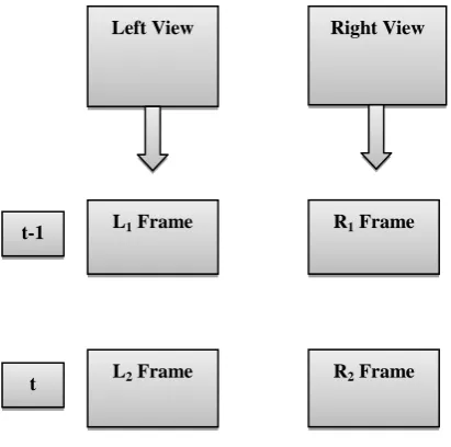
In both the reference and proposed schemes L1, L2 and R1
frames are encodedby the conventional intra coding scheme, for example, H.264, and on the decoder the R2 frame is
predicted using the information from these L1, L2 and R1
frames.
2.1.
Implementation of Reference
Scheme
The technique with which we compared our proposed technique is basically a four step algorithm that predicts the R2 frame using the other three frames. These steps are as
follows:
1. The disparity vectors (dv) are calculated using the t-1 frames in both left and right view.
2. These disparity vectors are applied on the R1 frame
to get a representation of R1 frame in the left view.
We name this frame as L1 *
.
3. The motion vectors (mv) are then calculated using L1* and L2.
4. The motion vectors calculated are applied on R1
frame to get an estimation of R2 i.e. R2 *
.
The graphical representation of the algorithm is shown below for better understanding.
Left View Right View
L1 Frame
L2 Frame
R1 Frame
R2 Frame
t-1
[image:3.595.56.262.431.635.2]Step1:
Step2:
Step3:
Step4:
2.2.
Implementation of Proposed Scheme
The technique we propose uses the homography transformation instead of disparity vector estimation. This technique comprises of the following steps.
1. Calculation of homography parameters (H) using the R1 and L1 frames.
2. Motion vectors are calculated from L1 to L2 frame.
3. Homography transformation is applied on R1 frame
to get a representation of this frame in the left view. We name this representation as L1
*
.
4. The motion vectors calculated in step 2 are applied on L1* to get L2*.
5. Inverse homography transformation is then applied on L2
*
to get R2 *
which is an estimate of the R2
frame.
The graphical representation of the proposed technique is shown below for better understanding.
Left View Right View
L1 Frame R1 Frame
t -1
Calculate dv
Left View Right View
L1* Frame R1 Frame
Apply dv
t -1
Right View
R1 Frame
R2* Frame
t-1
t
Apply mv application
Left View
L1* Frame
t-1
L2 Frame
Calculate mv calculation
Step 1:
Step 2:
Step3:
Step4:
Step 5:
3.
RESULTS AND DISCUSSION
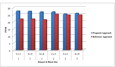
In order to test the proposed and reference technique weused two datasets; one of which has less number of objects and the relative depth of the objects in the scene was less whereas the other one has a greater number of objects and the depths of objects were relatively high. We assumed rigid and translational motion model here. We applied both the techniques on these data sets for different block sizes of motion and disparity vectors. The resultant PSNRs are listed below in table 1 and shown visually in fig. 5. The results indicate that the proposed homography based temporal interpolation technique outperforms the disparity based side information generation approach for smaller block sizes and the results are comparable for larger block sizes.
Left View Right View
L1 Frame R1 Frame
t-1
Calculate H
Left View
L1 Frame
t-1
L2 Frame
t
Calculate mv calculation
Left View Right View
L1* Frame R1 Frame
Apply H
t -1
Left View Right View
L2 *
Frame R
2* Frame
Apply H-1
t
Left View
L1* Frame
t-1
L2* Frame
t
Dataset Block Size Proposed Approach(PSNR) Reference Approach(PSNR)
1 2 x 2 27.7232 22.0133
1 4 x 4 27.5238 21.9714
1 8 x 8 27.0246 21.5291
2 2 x 2 27.0346 25.3893
2 4 x 4 25.5749 24.8983
[image:6.595.55.531.71.153.2]2 8 x 8 26.0636 24.9319
Table 1: PSNR values for Proposed and Reference schemes
Fig. 5: Proposed Approach vs Reference Approach: the chart clearly indicates that the proposed approach beats the reference approach.
4.
CONCLUSTION
In this paper we presented an improved method for side information generation using homography-based temporal interpolation. The proposed technique was tested against the method proposed by Artigaset. al, for multiview distributed video coding. Both techniques were implemented in Matlab and PSNR values were obtained. The PSNR values indicated that the proposed technique performs well than the reference techniques for smaller block size. Experiments were also performed for larger block sizes. The results were found comparable for larger block sizes.
5.
ACKNOWLEDGMENTS
We wish to gratefully acknowledge King Fahd University of
6.
REFERENCES
[1] Artigas, X., Torres, L., “Iterative Generation of Motion-Compensated Side Information for Distributed Video Coding,” Proceedings of the IEEE International Conference on Image processing, 2005.
[2] Artigas, X., Tarres, F., Torres, L.,“A Comparison of Different Side Information Generation Methods for Multiview Distributed Video Coding,” International Conference on Signal Processing and Multimedia Applications SIGMAP, 2007.
[3] Ye, S., Ouaret, M., Dufaux, F., Ebrahimi, T.,“Improved Side Information Generation with Iterative Decoding and Frame Interpolation for Distributed Video Coding,” IEEE International Conference on Image Processing, 2008.
[4] Ou, S., Liang F., “Improved Method for Construction of
0 5 10 15 20 25 30
2 x 2 4 x 4 8 x 8 2 x 2 4 x 4 8 x 8
1 1 1 2 2 2
PS
NR
Dataset & Block Size
Proposed Approach
[image:6.595.62.533.201.478.2][5] Borchert, S., Westerlaken, R.P., Gunnewiek R. K., Lagendijk, R.L., “On the Generation of Side Information for DVC,” Thirteenth Annual Conference of the Advanced School for Computing and Imaging, Heijen, the Netherlands, 2007.
[6] Ascenso, J., Brites, C., Pereira, F., “Improving Frame Interpolation withSpatialMotion Smoothing for Pixel DomainDistributed Video Coding,” 5th EURASIP Conference on Speech and Image Processing, Multimedia Communications and Services, 2005. [7] Abdul-Jauwad, S. H., Ullah, R., Ullah, F., “A Simple
Method to Recover 3-D Rigid Structure from Motion using SIFT, RANSAC and the Tomasi-KanadeFactorization,” International Journal of Computer Science Issues, Vol. 9, Issue 5, No 3, September 2012.
[8] Ouaret, M., Dufaux, F., Ebrahimi, T., “Multiview Distributed Video Coding with Encoder Driven Fusion,” 15th European Signal Processing Conference, 2007.
[9] Ouaret, M., Dufaux, F., Ebrahimi, T.,“Iterative Multiview Side Information for EnhancedReconstruction in Distributed Video Coding,” EURASIP Journal on Image and Video Processing, Volume 2009.
[10] Sukthankar, R., Stockton, R.G.,Mullin, M.D., “Smarter presentations: exploiting homography in camera-projector systems” Eighth IEEE International Conference on Computer Vision (ICCV), 2001.
![Fig. 1: Distributed Video Coding scheme [2].](https://thumb-us.123doks.com/thumbv2/123dok_us/8098466.786943/1.595.313.518.332.575/fig-distributed-video-coding-scheme.webp)
![Fig. 2: Homography matrix H relating one view to another [9]. Warped frame](https://thumb-us.123doks.com/thumbv2/123dok_us/8098466.786943/2.595.55.278.558.736/fig-homography-matrix-h-relating-view-warped-frame.webp)