2016 International Congress on Computation Algorithms in Engineering (ICCAE 2016) ISBN: 978-1-60595-386-1
1 INTRODUCTION
The mobility of the tracked vehicle describes the per-formance of the average cross-country speed for the vehicle to pass through a certain region. Such perfor-mance is actually a final result under the impact of the vehicle itself, terrain environment and many other factors. For the research of the vehicle mobility, there are generally the theoretical analysis method, the test method and the analogue simulation method. The theoretical analysis method is to research the vehicle mobility through mathematical analysis of the theo-retical formula. However, not all phenomena can es-tablish a strict theoretical formula. Therefore, the test method is also an important method to research the vehicle mobility, which makes statistics and summa-rization of the empirical formula through repeated tests. The analogue simulation method is to establish a mobility model based on the theoretical formula and empirical formula, and conduct research through the analogue simulation. With the development of the simulation technology, the research on the vehicle mobility based on the analogue simulation plays an increasingly important role.
The representative of the computer simulation method is the NATO Reference Mobility Model
(NRMM) developed from the US Army Mobility Model-75. Since it was firstly developed, NRMM con-tinues to be upgraded, and now it is commonly referred to as NRMM II. It not only provides reference stand-ards for the evaluation of the mobility performance of vehicle equipment in NATO countries, but also pro-vides underlying computing support for the equipment mobility analysis when being integrated in some other tactical, analytical and wargaming models.
NRMM is an equilibrium model, which researches the relationship between the maximum traction and speed according to the relationship between the vehi-cle’s engine, transmission and ground features. It ob-tains the maximum possible kinematic velocity by the calculation of the traction and various resistances, and gives possible speed in different terrain areas com-bined with the features of different road surfaces. NRMM is comprised of a number of sub-models, for example, the transmission performance model, vehi-cle-ground system model, climbing model (which is horizontal and vertical), steering performance model, vehicle-vegetation system model, braking perfor-mance model, wading model and so on. These sub-models are responsible for simulation calculation for different aspects of the ground mobility. The basis of calculation is the result of the laboratory
investiga-Mobility Simulation Framework of Tracked Vehicle
in Virtual Environment
Bo Dong, Lu Chen & Yinling Zhang
Operational Experiment Center, Armored Force Academy, Bengbu, Anhui, China
ABSTRACT: This paper analyzes the modeling methods and characteristics of the mobility of the tracked vehicle. According to the demand of the virtual simulation on both accuracy and velocity of the model computa-tion, this paper establishes a mobility simulation framework of tracked vehicle that is suitable for fast simulation calculation based on its dynamics and kinematics principles. The framework combines the principles with soft-ware of Matlab. In the framework, the vehicle mobility model is established based on the simplification of the vehicle mechanics, trafficability, obstacle crossing and other mathematical principles, which is also verified iter-atively. Matlab ensures the computational efficiency and the consistency of pillars in the framework. The framework is characterized by the versatility, extendibility, reusability, and its effectiveness is validated by the simulation experiments and real vehicle test. In summary, the framework provides modelers a feasible solution when modeling relevant simulations such as virtual training system.
tion and field test. Therefore, NRMM is a semi -empirical model.
Virtual simulation is an important part of simulation technology. The research on the vehicle mobility based on the virtual simulation is mainly used for the applications of the vehicle driving training, perfor-mance testing and other simulation systems with a three-dimensional scene. The virtual environment has special requirements on the accuracy and speed of the simulate calculation. Based on these special require-ments, this paper researches a mobility simulation framework of tracked vehicle in virtual environment, thus providing a useful reference for the virtual train-ing of the tracked vehicle, and improvtrain-ing the reality and accuracy of the vehicle movement in the training system.
2 MOBILITY SIMULATION DEMANDS OF
TRACKED VEHICLE IN VIRTUAL ENVI-RONMENT
The motion of the tracked vehicle is a very complex process, which is a combined action of the vehicle performance and external environment. Therefore, the mobility simulation of the tracked vehicle in virtual environment has special requirements on the accuracy and velocity of the calculation.
On one hand, the vehicle mobility depends on the power transmission of the vehicle and the associated constraints between various components so that the simulation requirements shall be as accurate as possi-ble. For example, the kinetics simulation software for various types of vehicles, Ansys, ADAMS / ATV, DADS and RecurDyn can provide parametric model-ing for the main parts in the track system, assembly of the entire track system, kinetics simulation and other functions. On the other hand, in addition to conduct calculation about the power transmission, the virtual simulation system of the vehicle shall also render the scene and conduct interactive operation. There are multiple physical movements in the simulation scene. In order to meet the needs of the system on the im-mersion, reality and real time simulation, it is
neces-sary to reduce resource consumption of other calcula-tions.
Considering the simulation accuracy, the vehicle maneuver model shall be detailed and complex as much as possible; considered the simulation speed, the vehicle mobility calculation model shall be simplified as much as possible, so as to ensure the real time sim-ulation. Therefore, the mobility simulation of the tracked vehicle in virtual environment is unable to adopt the kinetics simulation software mentioned above, because they are mostly for the product design or product performance simulation. The established model is complex with a large amount of information and need massive calculation, which is unable to meet the requirements of real time virtual simulation, and unsuitable for the virtual simulation system. In partic-ular, the simulation and calculation of the prototype model established by the professional software can not run without the professional software environment. Its software environment generally has higher require-ments on the system and hardware, with an excessive calculated quantity. The development and simulation design of the mobility model of the tracked vehicle in virtual environment shall be based on the system size and other specific needs, and make appropriate accu-racy and speed.
3 MOBILITY SIMULATION FRAMEWORK OF
TRACKED VEHICLE IN VIRTUAL ENVI-RONMENT
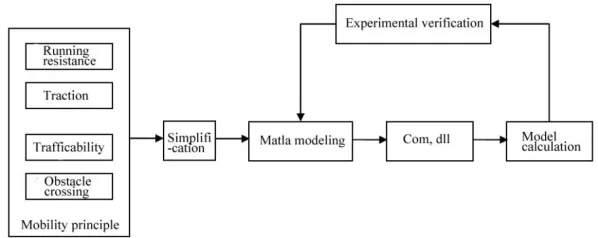
[image:2.516.110.409.527.646.2]Based on the above analysis, the mobility modeling for the tracked vehicle in virtual environment is un-suitable to adopt the professional simulation software with complexity of numerical calculation, but it is necessary to establish an appropriate model. As the vehicle mobility issue actually requires a considerable amount of numerical calculation, we consider to use Matlab tool for joint development in order to improve computational efficiency. In addition to using power-ful data computing capabilities of Matlab, it also has a good expansibility. The mobility model framework of the tracked vehicle in virtual environment is shown in Figure 1.
The main research content of the frame includes the mobility principle of the tracked vehicle and simplifi-cation, mathematical modeling and compiling, testing and verification based on Matlab.
3.1 Mobility principle and simplification
3.1.1Interaction between track and soil
The track is a removable road of the tracked vehicle, which can continuously roll out in front of the vehicle, let the vehicle pass through, and then be rolled back by the vehicle. In 1950s, Baker and Reese proposed to express the relation between the kinetic resistance and drawbar pull on sliding by the use of soil properties, and gave out an exact solution to the track issues.
Track-soil relations mainly research the running re-sistance of the track and traction of the tracked vehicle, with the following theoretical basis:
(1) Baker calculation formula
1
1
( 1)( )
n n
n c
bL W
E
k bL
n k
b
E represents the work which is done by the track with the length of L and width of b formed by the compacted soil.
(2) Kogure calculation formula
According to the soil pressure test which is similar to Baker, a Japanese scholar Kogure obtains the com-paction resistance:
2
0 0
0 0
cos 2
ln mm Rc
MM mm
bp P p
F
K p P p P
(3) Coulomb equation
Maximum thrust of soil is: FHmaxAc W tan
3.1.2Mollisol trafficability
Trafficability, namely, the cross-country ability, refers to the vehicle ability to pass through a variety of grounds and terrains. The vehicle trafficability on uneven ground is closely related to the road surface spectrum of vehicle, suspension system, vibration and other issues. However, in this paper, we just research the mollisol trafficability. On one hand, the mollisol trafficability of the tracked vehicle depends on soil conditions; on the other hand, it is related to certain characteristics of the vehicle. We generally believe that the moving ability of the vehicle on soft soil de-pends on the drawbar pull (DP), that is, the difference between soil thrust (H) and running resistance (R):
DPHR
DP not only represents the soil strength reservation, but also represents the ability to generate acceleration, climbing or traction load by the vehicle. In addition to
this formula, there are also other detailed formulas to reflect and assess mollisol trafficability of the vehicle.
3.1.3Geometric trafficability (obstacle crossing abil-ity)
The vehicle loses trafficability under cross-country conditions mainly because of failure in crossing a variety of geometric obstacles, rather than the firm-ness of the soil and unevenfirm-ness of the ground. There-fore, the obstacle crossing performance of the vehicle is also called as the geometric trafficability.
The vehicle loses the trafficability in case of geo-metric obstacles, and such cases can be divided into the following categories:
(1) Loss of trafficability due to lack of traction or adhesive force
When the vehicle climbs at a constant speed, it is unable to move forward, because the uphill resistance and rolling resistance generated by the vehicle weight is greater than the maximum traction of the vehicle. When the ramp surface or ramp-free road surface is relatively slippery, the track adhesion property gets worse. Although the power transmission system of the vehicle has sufficient torque, the vehicle is unable to move forward or even slide down muddy or snowy roads due to the running gear slipping.
(2) Loss of trafficability due to the vehicle contour encountering obstacles
In case of cross-country running, the vehicle may not move forward due to the front, rear and bottom of the vehicle encountering obstacles. For example, the bottom encounters convex obstacles, that is, the so-called “bottoming”; the front of the vehicle is stuck by concave obstacles; the longer rear overhang will also be stuck by the concave, but more common for the wheeled vehicles. If the strength of the convex or concave obstacle is not high (such as soft soil), the vehicle is likely to collide with the obstacle to pass through.
(3) Loss of trafficability due to the vehicle losing stability
The stability of the vehicle includes lateral stability and vertical stability. The instability includes lateral and longitudinal overturning.
(4) The cause of obstruction by vegetation obstacles Vegetation mainly refers to trees. When the space between trees is greater than the width of the vehicle, the vehicle can decelerate to pass through; if the space between trees is less than the width of the vehicle, and the diameter of the tree is large enough, the vehicle is unable to pass through, resulting in reduction in the average speed of the vehicle. These two cases make the vehicle trafficability get worse.
(5) Discordance between the water entry of water-way vehicle and the embankment geometry
the embankment; the front adhesion weight reduces and slides underwater due to the buoyancy and axle load transfer, so the vehicle is submerged in water; the vehicle is bottoming under the surface of water and ramp, resulting in stranding.
The ability to pass through the obstacles by the ve-hicle not only depends on the geometric dimension of the obstacle, but also is related to the geometric di-mension and center-of-gravity position of the vehicle. Only with an appropriate combination can it constitute a condition for the vehicle to pass through. The above factors affecting the trafficability can be predicted and judged in strict accordance with the condition formula from the perspective of the geometry.
3.2 Mathematical modeling and code compiling based on Matlab
The above principle equations related to vehicle mo-bility are all complex mathematical equations. If we program the equations directly, the implementation is difficult to achieve, and the calculation will be ineffi-cient. So Matlab can be used to complete modeling. Matlab not only has a superior numerical calculation capability, but also has a good extensibility, which provides C/C++ calling interface and complies com-monly-used COM components, dynamic link library (DLL) or C/C++ language code so that Matlab pro-gram can run independently from Matlab environ-ment.
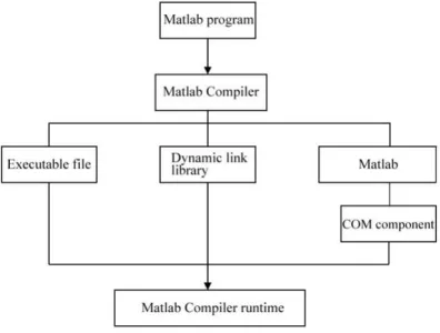
[image:4.516.54.252.500.650.2]Visual realization of the Matlab compiler compiles the above files by the Matlab program. In particular, the design idea of the later version of Matlab7.0 is significantly different from that of Matlab6.5 and earlier versions of the compiler. The earlier versions of Matlab6.5 focus on how to compile the Matlab program into C/C++ program; due to the use of MCR technology, the compiler which is come out after Matlab7.0 focuses on compiling the Matlab program into MCR (Matlab Compiler Runtime) executable program. Its basic technical architecture is shown in Figure 2:
Figure 2. Development process based on Matlab.
4 SIMULATION REALIZATION AND
VERIFI-CATION
In order to verify the simulation framework proposed in this paper, we establish a simplified mobility model of a tracked vehicle, carry out a simple simulation in a particular virtual environment by the way of Matlab joint simulation and the field measurement of the mo-tion parameters of the vehicle, and verify the effec-tiveness of the model through comparison with the simulation results, equipment performance parameters and real vehicle test results.
4.1 Simulation verification
We carry out a preliminary development and verifica-tion of the simulaverifica-tion framework proposed in this paper on an ordinary desktop, and we take uniform motion simulation as an example for verification.
The vehicle motion is a combined action of the traction and external resistance, without exception of the track. Its equilibrium equation is [4]:
js gg k p
g F F F F
F
F
The left side of the equation is the traction of the tank, and the right side is respectively the rolling sistance, uphill resistance, air resistance, drawbar re-sistance and acceleration rere-sistance. After brining in the calculation formula of various forces, the follow-ing equation can be obtained:
dt dv g G F
CAv G
fG r
i T
gg z
i
e cos .
sin cos
15 21
2
Where: Te is the engine torque; ii is the total drive ratio of the drive system in the gear I; is the efficiency; rz is the radius of the driving wheel; f is the rolling resistance coefficient; G is the vehicle weight; is the road surface gradient; C is the air resistance coefficient; A is the frontal area;
is an included angle of the pulling rope and ground; is the mass addition coefficient.In order to maintain uniform linear motion, the ve-hicle shall meet driving conditions and conditions attached:
gg k p g j
t F F F F F
F
Assuming that the vehicle moves on a level road at a lower speed without track slip and slide, the overall running speed of the vehicle can be obtained by the following formula:
z e
r i n v0.377
Where: v is the speed of the vehicle; ne is the engine
driving wheel, of which ne andTe in the previous formula are restrained by the engine characteristic curve. Major codes in Matlab are shown as follows:
G=G;
ii=[3.42 1.89 1.280.91 0.76];% drive ratio at each gear
rz=0.25;
i=4.40; % drive ratio
ngk=[800 800 800 800 800];% Minimum engine speed at each gear
ngm=[5400 5400 5400 5400];% Maximum engine speed at each gear
ugk=0.377*rz*ngk(k)/i(k)*I; Vehicle speed in case of minimum engine speed at each gear
ugm=0.377*rz*ngm(k)/i(k)*I; Vehicle speed in case of maximum engine speed at each gear
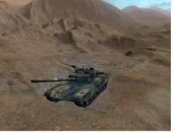
[image:5.516.92.214.297.390.2]This method can accurately calculate the minimum and maximum speed of the vehicle at each gear. We adopt DLL method to realize combined programming of C ++ and Matlab, and we drive vehicles in the vir-tual scene. Its visual effect of simulation is shown in Figure 3:
Figure 3. Simulation effect.
4.2 Real vehicle verification
Table 1. Test data.
No. R1(m) R2(m) R3(m) R4(m) 1 11.242 11.354 13.245 13.756 2 11.265 11.368 13.305 13.810 3 12.025 12.116 14.019 14.528 4 11.784 11.875 13.702 14.277 Average value 11.58 11.68 13.57 14.09
In order to verify the actual mobility performance of the equipment, we conduct a real vehicle test and measure some certain vehicle mobility performance parameters (mainly the steering performance). The experimental data are recorded as shown in Table 1.
R1 (m), R2 (m), R3 (m) and R4 (m) are respectively the turning radius of four different positions.
The minimum turning radius is calculated as fol-lows:
) ( 2 1 ) 2 ( 4
1 2
2 1
min R L l B b
R
Where: Rmin—minimum turning radius, (m);
1
R —the outermost turning radius of track outside the landing, (m);
L— the length of track to the landing, (m);
l
—the longitudinal offset of geometric center rela-tive to the center of gravity of the vehicle, (m);B—the center distance of the track, (m); b—the width of the rack shoe, (m).
For this type of tracked vehicle, after the measure-ment toward the length of track to the landing (L), the longitudinal offset of geometric center relative to the center of gravity of the vehicle (l), the center distance of the track (B) and the width of the rack shoe (b),
58 . 11 1
R is substituted into the Formula (7.1),
min Calculated value
R = 9.89 , Rmin Theoretical value = 7.86
and the relative error is
Rmin Calculated value-Rmin Theoretical value 9.89-7.86
= = 25.83%
Rmin Theoretical value 7.86
=
E .
In actual turning, the outer ground section always produces trackslip, but the trackslip direction is al-ways opposite to the motion direction of the tank; the inner ground section always trackslip, but the trackslip direction is always the same with the motion direction of the tank. The greater the slippage of trackslip is, the greater the difference between the theoretical value and the calculated value is. However, the trackslip is related to the nature of the ground, the speed of the vehicle, the turning radius and other factors. In general, the softer the ground is, the greater the speed is, and the smaller the turning radius is; the greater the slip-page and trackslip are, the greater the difference be-tween the theoretical value and the calculated value is. The research indicates that the actual minimum turn-ing radius is about 1.1~1.5 times of the theoretical minimum turning radius, and even reaches 1.6 times.
The test measures that
min Calculated value min Theoretical value
R = 1.26R , is within the
range of allowable error.
REFERENCES
[1] Zhang Shen, Guo Xi & Gao Wei. 2011. Geometry Traf-ficability modeling and simulation of wheeled armored vehicles. Journal of Armored Force Engineering Insti-tute, 25(5): 75-78.
[2] Sun Wei, Zhang Qi & Sun Feng, et al. 2008. Simulation of tracked vehicle in virtual environment. Computer
Simulation, 25(8): 258-262.
[3] Ouyang Guanjun, Fan Jinwei & Wang Yuxin, et al. 2007. Movement simulation algorithm research on ar-mored vehicle in virtual scene. Computer Simulation, 24 (12): 94-96.
[image:5.516.55.250.452.524.2]