2017 2nd International Conference on Software, Multimedia and Communication Engineering (SMCE 2017) ISBN: 978-1-60595-458-5
A Micro-buffered Router Architecture and Deflection Routing Algorithm
for Vertically Partially Connected 3D NoC
Jun-yu ZHAO, Qin-rang LIU, Chang LIU and Kai-xuan DENG
National Digital Switching System Engineering & Technological R&D Center, Zhengzhou, China
Keywords: Micro-buffered router, Routing algorithm, Vertically partially connected 3D NoC.
Abstract. Due to the problem of high hardware cost and low yield of the TSV in 3D NoC, the vertically partially connected 3D NoC with limit number of TSV has been researched widely. With respect to little research on micro-buffered router which is suitable for this topology and can further reduce hardware cost, a micro buffered router in vertically partially connected 3D NoC is proposed. This router is the 3D extension of MinBD and modifies side-buffer design in MinBD at the same time. Then a deflection routing algorithm based on this router is proposed. The productive output ports of the intra-layer communication packet are calculated according to the direction of destination node and the productive output ports of the inter-layer communication packet are calculated according to the distribution of TSV in current layer. The experimental results show that the network performance of our router is better than reference micro buffered routers’, while even is similar to traditional buffered routers in low and medium network traffic environment.
Introduction
With the increasing integration of digital circuits, the 2D NoC interconnect structure cannot provide enough scalability and transmission performance because of its layout constraints. The 3D NoC interconnect structure, which can be vertically stacked though the high speed TSV[1], can solve the above problems, but the introduction of TSV increases the overhead of the chip area. Studies have shown that for a set of 128bit bandwidth high density TSV[2] requires 12800um2, and for a set of 128bit bandwidth low density TSV[3] requires 32000um2. In addition, the introduction of high-speed TSV will lead to the problem of chip fabrication low yield[4]. Therefore, the vertically partially connected 3D NoC with limitation of the TSV number has been extensively studied.
In [5], the vertically partially connected 3D NoC is proposed for the first time, and Elevator-First routing algorithm is proposed. [6] and [7] reduce the hardware cost and power consumption of the router architecture through modifying deadlock avoidance method. All of the above algorithms use the buffered router architecture to realize routing. The non-buffered router and micro-buffered router can provide even better network transmission performance than the buffered routed architecture in the case of the network with the medium and low injection rate which is closer to the real network environment. Therefore, it is significant to research on the router architecture and the routing algorithm in vertically partially connected 3D NoC. A non-buffered router was proposed in [9], it used permute network structure to replace the arbitration and crossbar in traditional non-buffered router BLESS. In order to reduce deflection rate, [8] putted forward the MinBD router. This router will store deflected flits into a small count of buffer, and will inject it into network for port competition after a period of time. [10] added a link control structure between routers. When deflected flits are sent between two routers, the link control structure will send the packet back to the sender, thereby reducing the extra packet transmission path caused by deflection.
Router Architecture
The proposed router architecture is based on MinBD router, the overall structure is shown in figure 1. Each logical part of the diagram is placed in sequence of operations. The flits for inter layer transmission are stored in the TSV buffer, and the flits for intra layer transmission directly into the routing process; The flit that arrives at destination will be submitted at ‘eject’; The ‘TSV injection/ejection’ receives flits from TSV in ‘from-TSV inject’ before transfers flits to TSV in ‘to-TSV eject’; The ‘inject’ will receive flits from the local port; The flits will compete with the optimal output ports according to their own priorities in two dimensional permute network, and the flits that are not competitive to the optimal output ports are called deflected flits which are randomly exported to other ports; In order to reduce the deflection rate, the deflected flits may be stored in the side buffer, and the flits temporarily stored in the side buffer will re-injected into the network when their optimal output ports are available.
down_TSV_buffer up_TSV _buffer ej ec t fr o m -T S V i n je ct to -T S V e je ct in je ct si d eb u ff er e je ct si d eb u ff er i n je ct side buffer U N E D W S U N E D W S
ejected flit flit to be injected
2D permute network
[image:2.595.124.476.257.352.2]re d ir ec ti o n
Figure 1. 3D Router architecture.
The main difference between proposed router and MinBD are the design of the vertical link transmission and side buffer structure. The following two designs will be explained in detail.
TSV Injection/Ejection
In the traditional deflection routing algorithm, when a number of flits apply for the same port, the failure of the flit will be deflected to other port. At the same time, due to the structural characteristics of the vertically partially connected 3D NoC, if the flit is deflected to the vertical link, it will not only greatly increase the transmission delay of the flit, but also cause the waste of TSV link resources. Therefore, this paper proposes a new vertical link transmission. As shown in Figure 2, when the flit for inter layer transmission arrives at the router connected TSV, if the downstream router can’t receive this flit, and it will find the other TSV for inter layer transmission, which increases the latency, so the proposed router adds a small amount of cache in the U/D input port to temporarily store flits. At the same time, in order to avoid the flits for inter layer transmission residing in U/D port input buffer too much long time, the router will monitor the residence time of first flit in the TSV buffer. When the residence time exceeds a certain threshold, the router will choose the flit with low priority from horizontal link in the redirection phase to store in the TSV buffer, and thus free the horizontal link for flit stored in TSV buffer to be injected into network.
A B N E W S N E W S U
to-TSV eject from-TSV inject
down_TSV_buffer
Figure 2. TSV injection/ ejection scheme
0 2 1 3 N S W E
stage 1 stage 2
[image:2.595.337.509.623.719.2]0 1 2 3 N/W N/W N
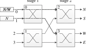
Figure 3. Permute network structure
Permutation Network Structure
[image:2.595.86.248.623.721.2]and the arbitration module 0 choose "exchange" operation, the flit in link 1 has to be deflected to the output of the W or E port. Taking into account the flit with multi optimal output ports, it can be outputted to the optimal output port regardless witch arbitration module it outputted to in phase 1. Therefore, the proposed router structure can avoid this situation by modifying the flit prioritization method in the phase 1 of the permutation network structure. No. 0 and No. 1 arbitration module adopts the following strategy in the comparison of the flits priority: when both flits have multiple optimal output ports, randomly select one flit with higher priority; when only one flit has a plurality of optimal output port, another flit has higher priority; when both flits have only one optimal output port, select one flit with higher priority according to the original strategy. Under the premise of not violating the original priority allocation strategy, the new permutation network structure can avoid the unnecessary deflection of the low priority flit and improve the routing efficiency.
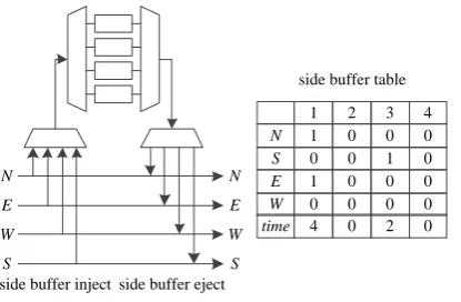
Side Buffer Structure
In order to reduce the deflection, a new side buffer structure is proposed in this paper. The deflected flits will be temporarily saved into side buffer, and will be inject into network when the optimal output port being available or outputting deflected flit. The proposed side buffer structure is shown in Figure 4. The router records the optimal output port and storage time of each flit in the side buffer through the side buffer table. The horizontal headers in thecorresponding to each buffer cell in side buffer. N, S, E, W in table’s vertical headers mean the optimal output port of each flit in the side buffer. The time in table’s vertical headers is used to record the storage time of data flits in the corresponding side buffer cell, and side buffer cell is empty when the corresponding time is 0.
2 3 4
1
0 0 0
1
N
0 1 0
0
S
0 0 0
1
E
0 0 0
0
W
0 2 0
4
time N
E
W
S
N
E
W
S
side buffer table
[image:3.595.200.408.370.506.2]side buffer eject side buffer inject
Figure 4. Side fuffer design.
In proposed router, the ‘side buffer inject’ structure design is in front of ‘side buffer eject’, and flits in side buffer need to wait for the optimal output port link to be idle to inject the network. Therefore, ‘side buffer inject’ should try to ensure that the flits in the side buffer can be injected when it select flit to store. In addition, in order to avoid flit storing in side buffer too much long time, the proposed router sets the longest storage time for the flit in the side buffer. When flit’s storage time exceeds the threshold value, it will be injected into the network in ‘side buffer eject’ unless its optimal output port is occupied by golden flit. Algorithm 1 describes the scheduling strategy of side buffer.
Algorithm 1. Side buffer scheduling policy
//‘side buffer inject‘ if(available buffer cell>0)
if(there is a flit which’s sorage time is over the threshold) if(the optimal output port of this flit is outputting deflected flit) store the deflected flit into side buffer;
elseif(the optimal output port of this flit is not outputting golden flit) store the this flit into side buffer;
else
randomly select deflected flit to store;
elseif(there is a output port which is optimal output port of flit in the side buffer is ocuppied by a deflected flit) store this deflected flit into side buffer;
randomly select deflected flit to store; //sidebuffer inject
if(available ouput port>0)
if(there is a flit which’s sorage time is over the threshold and its optimal output port is available) output this flit to its optimal output port;
elseif(there is a flit in the side buffer witch’s optimal output port is available) output this flit to its optimal output port;
Routing Algorithm
The routing algorithm can be divided into two categories: inter layer transmission and intra layer transmission. When the destination node is not in current layer, the flits need to be transmitted by inter layer transmission method and they have to find TSV at first. Therefore, each router needs to maintain the TSV table which stores the location of the TSV to select the TSV for inter layer transmission.
TSV table
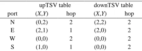
[image:4.595.184.412.428.510.2]The TSV table is set up by the warm-up phase of the system, and it can be updated constantly according to the TSV’s status in the running phase of the system. It can be divided into up TSV table and down TSV table. Up TSV table is used to store the up TSV’s location in the current layer, down TSV table is used to store the down TSV’s location in the current layer. Unlike the TSV table in [4] that stores all the TSV location information, the proposed TSV table only needs to store the location information and distance information of the nearest TSV from the 4 ports of the router. This design can enhance the scalability of the traditional TSV table design, because the size of the TSV table will not increase with the increase of the topology. Table 1 shows the design of TSV table with the example of the node (1,1,1) in Figure 1.
Table 1. TSV design of point(1,1,1)in fig 1.
upTSV table downTSV table port (X,Y) hop (X,Y) hop
N (0,2) 2 (2,2) 2
E (2,1) 1 (2,0) 2
W (0,0) 2 (0,0) 2
S (1,0) 1 (0,0) 2
Routing Algorithm
Basing on the router structure and TSV table, this paper designs a deflection routing algorithm. Flits for intra layer transmission calculate the optimal output port according to the location relationship between destination node and current node. Flits for inter layer transmission calculate the optimal output port according to current node and TSV table. The following is a detailed description of the two types of transmission methods for flits to calculate the optimal output port.
The flits for intra layer transmission calculate optimal output port according to the relationship between the current address (Xcur, Ycur) and the destination address (Xdst, Ydst). When the Xcur is greater
than Xdst, the east output port will be added to optimal output port set, and conversely the west port
will be added to the optimal output port set. When Ycur is greater than Ydst, the north port will be added
to optimal output port set, and conversely the south port will be added to the optimal output port set. The flit data transmission between layers is calculated according to the following formula:
( , ) .
Disdis dest TSV TSV hop
Algorithm 2. 3D Routing Algorithm
//Zcur: the current layer; Zdst: the destination layer if (Zdst>Zcur)
if (the current node is the router connects up TSV and U port is available) output to U port;
else
calculate the optimal output port through inter layer transmission; elseif (Zdst<Zcur)
if (the current node is the router connects down TSV and D port is available) output to D port;
else
calculate the optimal output port through inter layer transmission; else
if (current node is destination) submit;
else
calculate the optimal output port through intra layer transmission;
Evaluation
Methodology
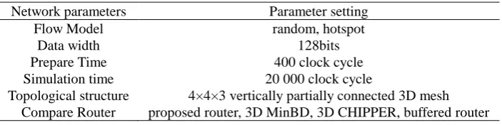
In the experiment, we use Verilog HDL to carry on the simulation. We compare the performance of proposed router with 3D MinBD router, 3D CHIPPER router and buffered router. The 3D MinBD router and 3D CHIPPER router are modified from MinBD router and CHIPPER router respectively by TSV injection/ejection and suit themselves for vertically partially connected 3D NoC, and they all use the proposed deflection routing algorithm for data transmission; the buffered router refers to the router in [4], and the buffered routing algorithm is carried out. The network parameters of experiment are shown in Table 2. Hotspot traffic mode refers that there is a hotspot in the network, and each node has 20% probability of sending flits to this hotspot. In order to simplify the experiment, seven fixed positions are selected to establish the TSV.
Table 2. Experiment parameter setting.
Network parameters Parameter setting
Flow Model random, hotspot
Data width 128bits
Prepare Time 400 clock cycle
Simulation time 20 000 clock cycle
Topological structure 4×4×3 vertically partially connected 3D mesh Compare Router proposed router, 3D MinBD, 3D CHIPPER, buffered router
Performance Analysis
In order to evaluate the performance of each router, the average delay information and the average deflection rate are compared. The average delay information represents the average clock cycle consumed by the flit from the source node to the destination node. The average deflection rate means the times that the deflection occurred of each flit during routing.
[image:5.595.123.475.494.582.2](a) (b) (c)
Figure 5 (a) shows the performance comparison in random traffic model. The proposed router can provide similarly performance in medium and low network traffic with reference buffered router. But with the increase of network load, it makes the network to reach saturation earlier. 3D MinBD router and 3D CHIPPER router has the same TSV injection/ejection with proposed router, but the 3D CHIPPER never store deflected flits and the flits stored in 3D MinBD’s side buffer may be deflected again after they re-inject into network. So the performance of the former two routers is lower than that of proposed router. Figure 5 (b) shows the performance comparison in hotspot traffic model, when the injection rate is up to 0.15, the network performance of proposed router and 3D MinBD router is better than reference buffered router. The reason of that is the presence of hotspots in the network will cause congestion near the hotspot node. Reference buffered router will store flits into the buffer when it encounters congestion, and send flits until the ahead flits have been sent already. It does not make full use of non-congested nodes around the hotspot. But the micro buffered router can deflect flits to other non-congested nodes to alleviate impact of congestion.
Figure 5(c) shows the average deflection rate comparison in the random traffic mode among the three micro buffered routers. It can be seen that proposed router has lowest deflection rate, because the TSV injection/ejection structure, permute network structure and side buffer structure, in a manner, all reduces probability of deflection of flit in routing. Although the 3D MinBD router adopts TSV injection/ejection structure, but the flits stored in its side buffer will participate port competition when they are injected into network, so they might still be deflected to non-optimal output ports. The 3D CHIPPER witch does not side buffer structure has highest average deflection rate.
Summary
In this paper, we propose a micro-buffered router architecture and a corresponding deflection routing algorithm for vertically partially connected 3D NoC. The proposed router is based on the MinBD. It reduce deflection rate by modifying side buffer structure and permute network structure, and suit itself to vertically partially connected 3D NoC by TSV injection/ejection structure. In the proposed routing algorithm, the flits for inter layer transmission calculate the optimal output port according to the TSV table and destination. And the flits for intra layer transmission calculate the optimal output port according to the location relationship between current node and destination. The experimental results show that the proposed router can provide better network performance than the reference non-buffered router, and it can provide the similar network performance with the reference buffered router in the low and medium network traffic environment.
References
[1] Pavlidis V F, Friedman E G. 3-D Topologies for Networks-on-Chip[J]. IEEE Transactions on Very Large Scale Integration Systems, 2007, 15(10):1081-1090.
[2] Sangki H. 3D super-via for memory applications[C]//Micro-Systems Packaging Initiative (MSPI) Packaging Workshop. 2007.
[3] G. Plas G V D, Limaye P, Loi I, et al. Design Issues and Considerations for Low-Cost 3-D TSV IC Technology[J]. 2011, 46(1):293-307.
[4] Ouyang Y, Han Q, Liang H, et al. A distributed routing algorithm for reliable communication in vertically partially connected 3D NoC[J]. Journal of Computer-Aided Design & Computer Graphics, 2014, 26(3):502-510.
[5] Dubois F, Sheibanyrad A, Bahmani M. Elevator-First: A Deadlock-Free Distributed Routing
[6] Lee J, Choi K. A deadlock-free routing algorithm requiring no virtual channel on 3D-NoCs with partial vertical connections[C]// IEEE/ACM International Symposium on Networks on Chip. ACM, 2013:1-2.
[7] Salamat R, Ebrahimi M, Bagherzadeh N. An Adaptive, Low Restrictive and Fault Resilient
Routing Algorithm for 3D Network-on-Chip[C]// Euromicro International Conference on Parallel, Distributed and Network-Based Processing. IEEE, 2015:392-395.
[8] Fallin C, Nazario G, Yu X, et al. MinBD: Minimally-Buffered Deflection Routing for
Energy-Efficient Interconnect[C]// IEEE/ACM Sixth International Symposium on
Networks-On-Chip. IEEE Computer Society, 2012:1-10.