2018 International Conference on Modeling, Simulation and Optimization (MSO 2018) ISBN: 978-1-60595-542-1
The Optimization Simulation of Pulsed Magnetic Field Coil
Based on Ansoft Maxwell
Yang JU
*, Hai-bin ZHOU,
Jing-feng YU,
Jiang-wei FAN
and Hai-sheng XU
Systems Engineering Research Institute, Beijing 100094, China *Corresponding author
Keywords: A method, Ansoft Maxwell, High-intensity magnetic field, Coil optimization.
Abstract. In order to study how a pulsed magnetic field emission coil produces a stronger magnetic field under the same excitation source, this paper makes a detailed analysis of A method, at the same time, the Ansoft Maxwell finite element simulation software is used to simulate irregular circular and triangular pulsed magnetic field emission coil. We can know from the results of analysis and simulation that the magnetic field intensity of a circular coil is stronger than that of a triangular coil when the radius of a circular coil is equal to the bottom edge of a equilateral triangle coil, that the inclination of the side of the coil can change the direction of the magnetic lines of flux, and the intensity of the magnetic field is strengthened. Several methods of optimizing the coil design in this paper can provide some guidance for the optimization design of the pulsed magnetic field coil.
Introduction
Pulsed high-intensity magnetic fields are widely used in aerospace, biomedicine and military fields[1-3]. Because the magnetic field produced by permanent magnets is small, and the cost of
superconducting magnets is higher. So, generally people use a coil to produce a strong magnetic field[4-8]. Under the condition of the same electrified current, by changing the shape, number and size
of the coil, the intensity of the magnetic field can be enhanced. The Huazhong University of Science and Technology has designed a layered coil to increase the magnetic field intensity[8-10]. Deduce the
analytical solution of the magnetic field distribution of the irregularly shaped coil is difficult. In order to obtain the magnetic field distribution characteristics of irregular shaped coils and the influence of different parameters on the distribution of the magnetic field, this paper makes a detailed analysis of
A method, at the same time, the Ansoft Maxwell finite element simulation software is used to simulate irregular circular and triangular pulsed magnetic field emission coil, the influence of the circular coil and the triangle aperture and the shape of the inner and outer holes on the distribution of the magnetic field is also analyzed[3]. Through the optimization of the coil the intensity of the
magnetic field has been strengthened.
Analysis of Simulation Principle
A method a common method to solve the problem of transient eddy current field. As shown in Figure 1, the solution domain is divided into excitation source area 1and non eddy current area
2
.The boundary condition of 1 is 1, the boundary condition of 2 is 2 1 , is
the Infinity boundary, for the Coils simulation, the excitation source area 1 represents exciting coil,
s J 1 2
Figure 1. Solving regional model.
The Maxwell equations:
H Js E (1)
t B E (2) The
is the conductivity of medium, the E is induction electric field, the H is magnetic field intensity, the Bis magnetic flux density, the Jsis excitation alternating current, it is important tonote that Jsonly exists in the coil [10]. In summary:
1 1 2 2 1 0 1 0 s A J t A A (3) To ensure the uniqueness of magnetic vector potential, besides define the curl of A , it need to define the divergence of A, Coulomb gauge A 0 is introduced[5].According to the formula 3 and the boundary condition, we use the weighted residual method to establish the finite element discretization equation of the transient eddy current field boundary value problem, and discretize the space, we can get a first-order differential equations of time. The matrix form is as follows:
t K A D A F
(4) Use the time step method of two point difference scheme to solve formula 4, it is know that:
1 1 1 1 1
t t
n D n n n D n n
K A F F K A
(5) In the formula,
1 is Backward Euler method,
1 2is Crank-Nicholson method,
2 3is Galerkin method.In the formula, for the eddy current area, the coefficient matrix and the variable matrix in unit e as follows:
0 0 0
0 0 0 0
ikxx ikxy ikxz
ikyx ikyy ikyz e
ik
ikzx ikzy ikzz
K K K
K K K
K K K
K , 0 0 0 0 0 0 ikxx ikxu ikyy ikyu e ik ikzz ikzu
ikux ikuy ikuz ikuu
D D
D D
D D
D D D D
T i Aix Aiy Aiz ui A
, ,
0 0 0 0
T e
i m
F
In the formula, the i , k is node number, the m active region marking[5].
For the non eddy current area, the coefficient matrix and the variable matrix as follows:
ikxx ikxy ikxz e
ik ikyx ikyy ikyz
ikzx ikzy ikzz
K K K
K K K
K K K
K
0e ik
D , Ai Aix Aiy AizT , ,
T
e e e e
i m imx imy imz
F F F F
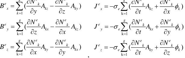
It can figure out the magnetic vector potentialA, through the relation between magnetic flux densityB and Induction current density J withA, the average flux density and the induced current density of each unit can be obtained at each time, it is as follows:
1 k 1 k 1 ( ) ( ) ( ) e e g
e k k
x kz ky
k
e e
g
e k k
y kx kz
e e
g
e k k
z ky kx
N N
B A A
y z
N N
B A A
z x
N N
B A A
x y
, k 1 k 1 k 1 ( ) ( ) ( ) e e ge k k
x e kz k
e e
g
e k k
y e kx k
e e
g
e k k
z e ky k
N N J A t x N N J A t y N N J A t z
The Lorentz force and its divergence can be further obtained.
Simulation Optimization of Circular Coil
The Inner and Outer Surface of the Coil not Inclined
line
W
内面 外面
(a) (b) (c)
Figure 2. 3D model of the coil.
The 3D model of the inner and outer surface of the coil is not inclined is show as Figure 2(a). In the picture, the outer and inner surface of the coil are marked. The whole coil is cylindrical, the air part of the inner hole is cylindrical. The line is the track of the magnetic field measurement. Line distance from the surface of the coil 3mm and perpendicular to the X-Y plane. Figure 2(b) is the 3D model of the inner is inclined and the outer is not incline. The air part of the inner hole is circular truncated cone. The radius ratio of the circle on both sides of the inner hole is 1:1.6. Figure 2(c) is the 3D model of the inner and outer surface of the coil is inclined. The air part of the inner hole is circular truncated cone. The shape of the whole coil is truncated cone. The radius ratio of the circle on both sides of the inner hole is 1:1.6.
[image:3.612.98.487.68.194.2]In the following simulation process, the pulse current in the coil is 5us and the amplitude is 100kA. The Ansoft Maxwell transient field analysis is used to extract the magnetic field data at the peak current.
[image:3.612.154.461.244.340.2]Table 1. The maximum value of the magnetic induction intensity.
Inner radius of coil (mm) 2.5 4 6 8 10
magnetizing induction intensity (T) 2.755 3.553 3.682 3.702 3.810
The Inner Surface Inclined and the Outer Surface not Inclined
Figure 3 is the distribution of the magnetic field in the vertical plane of a circular coil. The figure (a) is the inner and outer surface of the coil is not inclined, the figure (b) is the inner is inclined and the outer is not incline. It can be seen from the distribution of the cloud map that inner inclined surface changes the magnetic field distribution and makes the magnetic field focus on the direction of the incline of the inner surface.
(a) (b)
Figure 3. Magnetic field distribution cloud map.
Table 2. The maximum value of the magnetic induction intensity.
Inner radius of coil (mm) 2.5 4 6 8 10
magnetizing induction intensity (T) 3.526 4.190 4.223 4.322 4.410
Table 2 is the maximum value of the magnetic induction intensity on the measurement track line when the inner radius of the coil is changed at 2.5-10mm, the unit is Tesla. It can be seen from the table that the magnetic induction intensity increases with the increase of the inner radius when the outer radius is constant. Under the same radius, the intensity of the magnetic field produced by the coil of the inner surface inclined and the outer surface not inclined is higher than the coil of the inner and outer surface not inclined.
The Inner and Outer Surface of the Coil Inclined
[image:4.612.84.525.590.625.2]Table 3 is the maximum value of the magnetic induction intensity on the measurement track line when the inner radius of the coil is changed at 2.5-10mm, the unit is Tesla, it can be seen from the table that the magnetic induction intensity increases with the increase of the inner radius when the outer radius is constant. Under the same radius, the intensity of the magnetic field produced by the coil of the inner surface inclined and the outer surface not inclined is higher than the other two methods.
Table 3. The maximum value of the magnetic induction intensity.
Inner radius of coil (mm) 2.5 4 6 8 10
magnetizing induction intensity (T) 3.221 4.001 4.102 4.213 4.325
Simulation Optimization of Triangle Coil
The Inner and Outer Surface of the Coil not Inclined
Table 4. The maximum value of the magnetic induction intensity.
Inner radius of coil (mm) 2.5 4 6 8 10
magnetizing induction intensity (T) 2.634 3.361 3.543 3.602 3.752
The Inner Inclined and the Outer not Inclined
Table 5 is the maximum value of the magnetic induction intensity on the measurement track line when the inner length of the triangle sides is changed at 2.5-10mm, the unit is Tesla, It can be seen from the table that the magnetic induction intensity increases with the increase of the inner length of the triangle sides when the outer length of the triangle sides is constant. Under the same length, the intensity of the magnetic field produced by the triangle of the inner surface inclined and the outer surface not inclined is higher than the triangle of the inner and outer surface not inclined.
Table 5. The maximum value of the magnetic induction intensity.
Inner radius of coil (mm) 2.5 4 6 8 10
magnetizing induction intensity (T) 3.201 3.850 3.943 4.023 4.136
The Inner and Outer Surface of the Coil Inclined
[image:5.612.84.533.401.436.2]Table 6 is the maximum value of the magnetic induction intensity on the measurement track line when the inner length of the triangle sides is changed at 2.5-10mm, the unit is Tesla, it can be seen from the table that the magnetic induction intensity increases with the increase of the inner length of the triangle sides when the outer length of the triangle sides is constant. Under the same radius, the intensity of the magnetic field produced by the triangle of the inner surface inclined and the outer surface not inclined is higher than the other two methods.
Table 6. The maximum value of the magnetic induction intensity.
Inner radius of coil (mm) 2.5 4 6 8 10
magnetizing induction intensity (T) 3.031 3.475 3.632 3.855 3.923
Summary
This paper makes a detailed analysis of A method, at the same time, the Ansoft Maxwell finite element simulation software is used to simulate irregular circular and triangular pulsed magnetic field emission coil. We can know from the results of analysis and simulation that with the circular radius of the coil and the edge length of the triangle increase, the magnetic induction intensity on the surface of the coil is constantly enhanced; The magnetic induction intensity of the circular coil is higher than the magnetic induction intensity of the triangular coil when the radius of the circular coil and the triangular edge are equal; Under the same length, the intensity of the magnetic field produced by the coil of the inner surface inclined and the outer surface not inclined is higher than the other two methods. Through the optimization of the coil, the magnetic field has been focused and enhanced, and the intensity of the magnetic field has been strengthened. Several methods of optimizing the coil design in this paper can provide some guidances for the optimization design of the pulsed magnetic field coil.
References
[1] Song Yunxing. Multi-physics Coupling Mechanism in High Field Magnets [D]. Huazhong University of Science and Technolog, 2012.
[3] Zhang Yu-Heng. Theory of optimum designing for the systems of pulse strong magnetic field [J]. Acta Physica Sinica, 1980(9): 1121-1134.
[4] Guan Zhi-cheng, Su Hua-feng, Jia Zhi-dong. Department of Electrical Engineering and Applied Electronic Technology [J]. High Voltage Engineering, 2009, 35(11): 2735-2740.
[5] Wang Zhi-xuan, Wang Min, Gao Shi-xiang. Deduction of distribution magnetic strength close by current circle and computer emulation [J]. Computer Engineering and Design, 2007, 28(3): 706-709. [6] Jiang Chun, Mi Yan, Yao Chenguo, etc. Analysis of Braunbeck Coil for Pulsed Magnetic Field Generator [J]. High Voltage Technology, 2012, 38(5): 1150-1156.
[7] Xiao Huoxiu, Li Liang. Inductance Calculation for Pulse Magnets [J]. Transactions of China Eletrotechnical Society, 2010, 25(1):14-18.
[8] Qiu Li. Research on Pulsed High Magnetic Field Forming and Manufacturing Technology [D]. Huazhong University of Science and Technolog, 2012.
[9] Jiang Chengxi. Design and Realization of Pulse Power Supply System for Pulse High Magnetic Field [D]. Huazhong University of Science and Technolog, 2013.