~===========
SERVICE MANUAL
HP 9130K
Flexible Disc Drive
Service Documentation
ii
Table of Contents
Chapter 1: General Information
Introduction ... 1-1
General Description ... 1-1
Available Options ... 1-2
Environmental and Physical Specifications ... 1-2
Recording Specifications ... 1-2
Environmental Specifications ... 1-2 Physical Dimensions and Weight ... 1-3
Performance Specifications ... 1-3
Flexible Disc Media Use ... 1-4
Intro.duction ... 1-4
Operating Cleanliness ... 1-5
Handling Discs ... 1-5
Do ... 1-6 Don't ... 1-7
Write Protection ... 1-9
Chapter 2: Interface Information
Introduction ... 2-1
Interface ... 2-1
Primary Power Requirements ... 2-1
Signal Line Description ... 2-3
Input Control Lines ... 2-3
Output Status Lines ... 2-4
Typical Interface Drive/Receiver Circuit ... 2-8
Chapter 3: Theory of Operation
Introduction ... 3-1 Flexible Disc Recording Fundamentals ... 3-1
Index Pulse Shaping Network ... , ... 3-3
Write Protect Sensor ... " ... 3-3
Track 0 Switch ... , ... 3-3
Spindle Motor Drive Control ... 3-3
Head Position Control ... 3-4
Power On Circuit ... 3-4
Data Circuitry ... 3-4 Writing Data ... 3-4
iii
Chapter 4: Assembly Access
Introduction ... 4-1
Chapter 5: Maintenance
Introduction ... 5-1
Service Kit Contents ... 5-1
Drive Failure Analysis ... 5-2
Head Cleaning ... " .... 5-3
Termination Resistor IC U2F ... 5-3
Shunt Block U1E ... 5-3
Alignment and Adjustments ... 5-3
Introduction ... , .... 5-3
Spindle Motor Speed Adjustment ... , .... 5-3
Spindle Drive Belt Adjustment ... 5-4
Radial Head Alignment ... 5-7
Head Azimuth Alignment ... 5-8
Track 0 Switch Adjustment ... 5-9
Index Emitter/Detector Adjustment ... 5-10
Write Protect Switch Adjustment ... 5-12
Read/Write Test ... 5-12
DSU Controls and Indicators ... 5-13
Disc Service Unit Operation ... 5-16
Packaging Instructions ... 5-17
Test Point Location and Waveforms ... 5-19
Chapter 6: Schematic Diagrams
Introduction ... 6-1
Chapter 7: Replaceable Parts
Introduction ... 7-1
Figures
1-1 Physical Dimensions ... 1-4
1-2 Head/Media Critical Requirements ... 1-6
1-3 Damaged Media ... 1-8
1-4 Loading the Disc ... 1-9
1-5 Write Protect Tab Installation ... 1-9
2-1 Connector J2 Pin Out ... 2-1
2-2 Connector J1 Pin Out (Circuit Side) ... 2-2
2-3 General Control and Data Requirements ... 2-5
2-4 Connector Location ... 2-6
iv
2-6 Connector J3 Pin Out ... 2-7
2-7 Servo Electronics Board Jl ... 2-8
2-8 Typical Interface DriverlReceiver Circuit ... 2-9
3-1 ID and Data Field Content ... 3-1
3-2 Media Sector and Track Structure ... 3-2
3-3 Head Positioning Assembly ... 3-3
3-4 9130K Functional Block Diagram ... 3-5
3-5 Write Timing Diagram ... 3-6
3-6 Read Timing Diagram ... 3- 7
4-1 9130K Flexible Disc Drive Exploded View ... 4-2
4-2 Drive Board and Servo Board Removal ... 4-3
4-3 Front Panel and Latch Removal ... 4-4
5-1 Spindle Motor Speed Adjustment ... 5-4
5-2 Spindle Drive Belt Adjustment ... 5-5
5-3 9130K Test Setup ... 5-6
5-4 Radial Head Alignment Waveform ... 5-7
5-5 Head Assembly Retaining Screws ... 5-8
5-6 Head Azimuth Waveform ... 5-9
5- 7 Track 0 Switch Retaining Screw ... 5-9
5-8 Track 0 Waveform ... 5-10
5-9 Index Detector Retaining Screw ... 5-11
5-10 Index to Burst Waveform ... 5-12
5-11 Write IF Waveform ... 5-13
5-12 Write 2F Waveform ... 5-13
5-13 DSU Controls and Indicators ... 5-14
5-14 9130K/DSU Test Setup ... 5-16
5-15 Foam Latch Insert ... 5-17
5-16 Inner Box ... 5-18
5-17 Foam End Caps ... 5-18
5-18 Outer Box ... 5-19
5-19 Test Point Locations (09130-66501) ... 5-19
5-20 Test Point Locations (82901-66515) ... 5-20
6-1 Drive Electronics Board PIN 09130-66501 Schematic Diagram ... 6-3
6-2 Drive Electronics Board PIN 82901-66515 Schematic Diagram ... 6-5
6-3 Servo Electronics Board PIN 09130-66500 Schematic Diagram ... 6-9
6-4 Servo Electronics Board Component Locator ... 6-11
6-5 Drive Board PIN 82901-66515 Component Locator ... 6-12
Chapter
1
General Information
Introduction
This service manual provides detailed information for servicing the 9130K disc drive.
Service Philosophy
The 9130K Flexible Disc Drive is comprised of three serviceable areas: the mechanical drive assembly, the drive electronics assembly and the servo electronics assembly. All assemblies are serviced on the exchange program with the exception of some parts on the mechanical assembly. The field replaceable parts are outlined in the maintenance and assembly access sections.
General Description
The
HP
9130K rnini double sided flexible disc drive is a semi-random access mass storage system employing a flexible magnetic medium. It consists of a mini disc drive, a servo electronics circuit board and a drive electronics circuit board.Each drive module contains all the mechanical parts necessary for physically handling the disc. These include the drive spindle and motor, 2 heads each having read/write and erase capability, write protect sensor, track 0 sensor, index sensor, and activity LED on the front panel. Each drive module also contains a servo control board which controls the DC drive motor speed and a drive electronics board which interprets and generate control signals, controls movement of the read/write head to the correct position, and also reads and writes data.
The flexible magnetic medium used in the 9130K is called a flexible disc. The flexible disc measures 133.4 mm (5.25 inches) on a side and has a 3.8 cm (1.5 inch) hole for alignment on the disc drive spindle. The disc is enclosed in a protective polyvinylchloride (PVC) jacket with a slot for access to the recording surface. Both sides of the flexible disc are used for data storage.
The recording head in the drive module is positioned by a mechanism driven by a stepper motor and taut metal band. The head positioning mechanism operates in an open loop configuration, that is, there is no feedback to the drive electronics board to determine the actual position of the head.
1-2 General Information
Available Options
The following options are available with the 9130K flexible disc drive: Option #010
This option consists of drive board PIN 09130-66501.
Option #011
This option consists of drive board PIN 82901-60015 found in the 8290X series drives. Option #050
This option consists of the mechanical drive assembly with servo board and front panel PIN
4040-1838 and latch PIN 4040-1836 and associated hardware.
Option #051
This option consists of the mechanical drive assembly with servo board and front panel PIN
4040-1915 and grey latch PIN 4040-1914 and associated hardware.
Option #052
This option consists of the mechanical drive assembly with servo board and front panel PIN
4040-1915 and brown latch PIN 4040-1913 and associated hardware.
Environmental and Physical Specifications
Recording Specifications
HP Physical Track FormatRecordng Mode: Modified Frequency Modulated (MFM) Rotational Speed: 300 RPM ± 1.5% (± 4.5 RPM) Bit Density: 5456 BPI Track 34
Tracks Per Inch: 48
Sides Per Disc: 2 Tracks Per Side: 35
Sectors Per Track: 16
Bytes Per Sector: 256 (362 including overhead bytes)
Bytes Per Disc: 286,720 (formatted) 420,000 (unformatted) Transfer Rate
164,000 bits per second nominal burst rate.
Access Time
Track to Track Seek: 5 msec. max. Head Settling Time: 15 msec. max.
Spindle Motor Start Time: 250 msec. max.
Environmental Specifications
Operating LimitsTemperature:
+
100General Information 1-3
Relative Humidity: 20% to 80% with maximum wet bulb temperature not to exceed 29.4°C (85° F)
Altitude: 0 to 4572M (0 to 15000 feet)
Storage Limits
Temperature: - 41 ° C to 71 ° C ( - 40.5° F to 159.8° F)
Relative Humidity: 20% to 80% with maximum wet bulb temperature not to exceed 29.4° C (85° F)
Alignment Limits
Radial Alignment: 1.1 mils maximum of track center at track 16 measured at 20° C (68° F) and 50% humidity.
Azimuth: 18° maximum clockwise or counterclockwise on tracks 16 and 34. Power Requirements:
+
12VDC ± 0.6V @ 900ma nominal+
5VDC ± 0.25V @ 600ma nominalMedia Life
Revolutions 2,500,000 revolutions on any track.
Head Life: More than 15,000 hours of operation with
HP
media.Physical Dimensions and Weight
Figure 1-1 illustrates the physical dimensions. Weight: 2.04Kg (4.5 lbs)
Height: 85.85mm (3.38 inches) Width: 149.1mm (5.87 inches) Length: 203.2mm (8 inches)
Performance Specifications
Soft Read Errors: 1 in 109 bits read on inner most track Seek Errors: 1 in 106 seeks
See the 9130K Specification Document for further details.
1-4 General Information
8.37 (212.72)
~---(l~~6)---3.12 (79.37)
1.37
(34.92) SEE NOTE 3
*1.87*
*(47.62)*
1 4 - - - -6.12(155.57) _ _
~I
~===~=====::::~~
*5.87(149.22)*
~
1 4-337
=]
(85.72)
NOTES:
I. DIMENSIONS GIVEN AS INCHES(MILLIMETRES). 2. * DENOTES DIFFERING TANDON DRIVE DIMENSIONS. 3. THIS DIMENSION FROM BACK OF FACEPLATE.
Figure 1-1: 9130K Physical Dimensions
Flexible Disc Media Use
Introduction
The storage medium used in the HP 9130K disc drive, is a flexible disc commonly called a floppy. The flexible disc measures 133.4 mm (5.25 inches) in diameter and has a 27.5 mm (1.125 inch) hole for alignment on the disc drive spindle. The disc is enclosed in a protective plastic jacket with a slot for head access to the recording surface. Both sides of the flexible disc are used for data storage.
By using flexible discs indentified as "double-sided", up to .25 megabytes of data can be stored on each disc. Since some of the storage is used in subsystem overhead, the exact amount available for user storage depends upon the controller subsystem. Refer to the appropriate mainframe programming or reference manual for details. Double-sided flexible discs (HP part number 92190A, package of ten) are available from HP's computer supplies catalog, by calling the toll free order number 800-538-8787.
General Information 1-5
CAUTION
ONLY HP MEDIA IS APPROVED FOR USE IN THE 9130K FLEXIBLE DISC DRIVE. USE OF OTHER MEDIA MAY RESULT IN PREMATURE DISC FAILURE OR DAMAGE TO THE DRIVE. HP MEDIA WILL ALWAYS HAVE AN/HP LABEL ON IT.
HP RIGOROUSLY TESTS EACH BATCH OF MEDIA FOR ERROR RATE AND WEAR PERFORMANCE IN ADDITION TO INITIAL VENDOR QUALIFICATION. ONLY IN THIS WAY CAN HP ASSURE RELIABLE MEDIA PERFORMANCE.
THE USE OF NON-HP MEDIA FOR SINGLE USE APPLICA-TlONS SUCH AS DATA INTERCHANGE WILL PROBABLY NOT DAMAGE THE DRIVE OR MEDIA BUT, IF EXTENDED USE IS ANTICIPATED, THE DATA MUST BE TRANSFERRED TO HP MEDIA.
EXTENDED USE OF NON-HP APPROVED MEDIA WILL VOID WARRANTY AND SERVICE CONTRACTS ON THE INSTRU-MENTS.
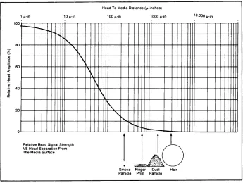
Operating Cleanliness
To prevent potential damage or data loss, it is extremely important to maintain the cleanli-ness of the disc and air within the disc drive. The disc drive should not be operated in an environment in which dust, smoke, moisture, oil or chemical vapor or other foreign matter are present. Also, be sure to strictly follow the disc handling gUidelines.
The critical elements involved in the read/write process are shown in Figure 1-2. The read/write heads must maintain contact with the media during the read and write opera-tions. Also shown are various types of contaminants and their size relationships. A contami-nant particle. hard enough and of the right size may scratch either the oxide coating of the disc or the head surface. Even if the particle is not hard enough to scratch, it may be hard enough to lift the head from the disc surface and cause data errors.
Handling Discs
The flexible disc is basically maintenance free, but it is delicate and MUST BE HANDLED CAREFULLY. Remember, the disc contains your valuable data and programs and should be treated accordingly. A good rule of thumb is to treat the disc as you would a valuable record album. Here are some specific DO's and DON'Ts to avoid loss of data or damage to the discs.
1-6
Generallnformation100
80
!
~ 60
« 'C os Q) J: Q) ~ 40
Qi
II:
20 1 win
r--
r-r-I'-o"
'\Relative Read Signal Strength VS Head Separation From The Media Surface
\
\
1\
~
Head To Media Distance (winches)
100Win 1000 win
I I
I\.
,,~
...
"
"'t--1
t
~~ ~:;;;~.;~.~.
. ..-AO
Smoke Finger Dust Hair Particle Print Particle
[image:10.611.117.462.89.349.2]10.0001'-in
Figure 1-2: Head/Media Critical Requirements
DO
Backup Disc Frequently
There is always a chance' of losing data when mass storage devices are accessed. There are many causes in any computer system-a programming bug, operator error, power failure, or hardware failure. In the case of flexible discs, another mode is possible-media failure from contamination or wearout. YOUR ONLY PROTECTION AGAINST DATA LOSS IS FREQUENT BACKUP OF DATA FILES.
Return Disc to Storage Envelope when Not in Use
This is the single most important thing to remember about handling a disc because it prolongs disc life by protecting it from dust and scratches. Be-tween uses discs should be stored upright in a dust free container. The box that the discs are shipped in, or a similar container, is a good choice.
Operate in a Clean Environment
General Information 1-7
Maintain Proper Temperature and Environment The proper operating range for the 9130K is 10 C (500
F) to 44 C (1110
F) and 20% to 80% relative humidity. While temperature is usually easy to control, it may be necessary to make special provisions to keep the humid-ity in the proper range. Although the disc will continue to operate outside the normal recommended humidity range, it will wear out more quickly and will produce a higher error rate.
Avoid Magnetic Fields
Since the data is stored as a pattern of magnetic fields on the disc, it can easily be erased by an external magnetic field. Avoid placing a disc near power transformers, magnets or large disc memories. Additionally, while HP goes to great lengths to confine the magnetic fields produced by CRT deflection shields, CRT's with magnetic deflection systems have been known to destroy data on discs, and it is a good idea to avoid placing discs on top of CRT's.
Remove Disc from Drive when Not in Use
Remove the disc completely from the drive when access is not needed for an extended period of time.
Use a Felt Tip Pen to Label Discs
Use a soft felt tip pen to label the disc, and be careful to write only in the label area provided. Avoid the exposed media while labeling the disc. If
possible, write on the large labels BEFORE applying them to the disc jacket.
Replace Discs Frequently
j l
~
Although discs are designed to provide several million revolutions of useful life (approx-imately 2 to 4 months of use), they will eventually wear out. The life of a disc is VERY dependent upon how carefully it is handled and how much it is used. If there are ever visible signs of abrasions on the disc, do an immediate backup and discard the worn disc.
DON'T
Do Not Touch the Exposed Surface of the Disc
1-8 General Information
Do Not Bend or Fold the Disc
The disc is flexible but will not operate if it is creased. Using ball point pens, rubber bands, paper clips, etc. can crease the disc.
Do Not Try to Clean a Disc
The inside surface of the disc jacket is covered with a special material that cleans the disc as it rotates. Any other method of cleaning may cause solvent damage to the media or scratch the disc, causing loss of data. If a disc becomes dirty or scratched, immediately copy the data to a new disc and dispose of the old disc.
Disc Loading
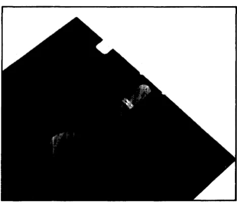
CAUTION
[image:12.614.171.405.404.605.2]IF MEDIA IS EVER DESTROYED (IF IT LOOKS ANYTHING LIKE THE PHOTO BELOW) IN YOUR 9130K DISC DRIVE, STOP USING THE DRIVE UNTIL IT CAN BE SERVICED. THIS IS EXCEPTIONALLY IMPORTANT, AS CONTINUED USE OF THE DRIVE WILL DESTROY MORE MEDIA. IMMEDIATELY CALL YOUR NEAREST HP SALES SERVICE OFFICE (SEE THE LIST IN THE BACK OF THIS MANUAL FOR THE NEAREST OFFICE).
Figure 1-3: Damaged Media
General Information 1-9
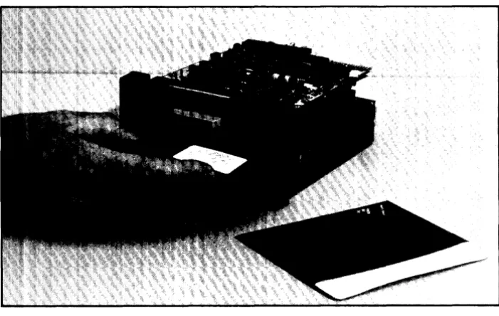
Figure 1-4: Loading the Disc
Write Protection
The disc has the capability of being write protected. This feature prevents the accidental erasure of data previously recorded on the disc. The write protect is enabled when the write protect notch on the jacket of the disc is covered (see Figure 1-4). When the notch is uncovered, data can be written on the disc.
The write protect notch may be covered by placing a tab over the notch on the top side of the disc jacket and then folding it over the edge to cover the notch on the bottom side. Installation of the tab is shown in Figure 1-5.
WRITE
PROTECT NOTCH
.,,---,L
o
TAB
o
Figure 1-5. Write Protect Tab Installation
FOLD OVER TO BACK OF DISC
[image:13.614.144.495.91.313.2]Chapter
2
Interface Information
Introduction
This chapter provides the interface information for the 9130K Flexible Disc Drive. The information provided in this chapter includes connector locations and pin-outs, signal line descriptions and typical interface driver and receiver circuits.
Interface
The flexible disc drive
110
connector (J1) is located on the rear edge of the drive electronics board. The 34 pin edge connector mates with the HP connector part number 1251-3916.Primary Power Requirements
+12VDC ±0.6VDC @ 900MA (MAX) +5VD ± 0.25VDC @ 600MA (MAX) Maximum ripple 100 MV PP
DC power is supplied through a 4 pin connector (J2). The mating connector (not supplied) is HP part number 1251-4525. Four contacts PIN 1251-4615 are also required.
The connector (J2) pin out is shown in Figure 2-1.
Pin Supply Voltage
1 + 12VDC
2 + 12V Return
3 +5V Return
4 +5VDC
2-2 Interface Information
The pin-out for J2 is shown in Figure 2-2.
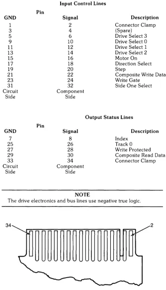
GND 1 3 5 9 11 13 15 17 19 21 23 31 Circuit Side GND 7 25 27 29 33 Circuit Side Pin Pin
Input Control Lines
Signal Description
2 Connector Clamp
4 (Spare)
6 Drive Select 3
10 Drive Select 0
12 Drive Select 1
14 Drive Select 2
16 Motor On
18 Direction Select
20 Step
22 Composite Write Data
24 Write Gate
32 Side One Select
Component Side
Output Status Lines Signal 8 26 28 30 34 Component Side NOTE Description Index Track 0
Write Protected Composite Read Data Connector Clamp
The drive electronics and bus lines use negative true logic.
[image:16.615.129.464.115.699.2]34 2
Signal Line Description
Input Control Lines
Drive Select Lines
Interface Information 2-3
There are four drive select lines which are used for selecting and de-selecting one of three disc drives attached to the controller.
When the logic level on the drive select line is low, the disc drive electronics are enabled and the drive will respond to step or Read/Write commands.
The drive select line must remain stable in the low state until the step or Read/Write command is completed.
When the logic level on the drive select lines are high, the input control lines and output status lines are disabled.
There is also a user installed option jumper available to utilize a fourth drive select line.
The disc drive address is determined by a select code shunt block located on the drive electronics circuit board. The drive select lines 1 through 3 provide a means of daisy chaining a maximum of three disc drives to a controller. An undefined operation may result
if more than one drive is assigned the same select code or if more than one of the drive select lines are low simultaneously.
Motor On
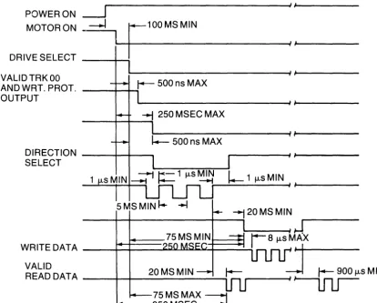
A low logic level on this line causes the drive motor to accelerate and stabilize in less than 250 msec. When this line goes high, the drive motor decelerates to a stop.
Direction Select and Step Lines
When a disc drive is selected, a low pulse greater than 1 /-Lsec. but less than 2 msec. appearing on the step line initiates head assembly motion. The direction of this motion is determined by the logic level appearing on the direction select line when the step pulse is issued. A high logic level on the direction select line when the step pulse is issued the direction of motion is outward (step-out) away from the center of the disc. A logic low on the direction select line results in the inward direction (step in) of motion toward the disc center.
To ensure proper positioning, the direction select line should be stable 1 msec. minimum prior to the step pulse and remain stable until 1 /-Lsec. after the step pulse. The access motion is initiated on the trailing edge of the step pulse.
Consecutive trailing edges of step pulses should not be less then 5 msec. apart.
The drive electronics will ignore step pulses if any of the following conditions exist: • The write gate line is low.
2-4 Interface Information
Composite Write Data
When the disc drive is selected, this line provides the bit serial composite write data pulses that control the switching of the write current in the selected head. The write electronics must be enabled by the write gate line.
Write Gate
When this line is low, the write electronics are enabled for writing data (read electronics are disabled). This line enables write current to flow in the selected read/write head.
Data is written under the control of the composite write data line and side one select line. Changes of state on the write gate line should occur before the first write data pulse. When the write gate line is high, all write electronics are disabled.
If a write protected disc is installed; the write electronics are disabled irrespective of the state of the write gate and side one select lines.
Side One Select
The Side One Select line defines which side of a two sided disc is used for information transfer.
A high logic level selects the side' '0" read/write head and a low logic level selects the side 1 read/write head.
Output Status Lines
Index
An index pulse occurs once every revolution of the disc (200 msec. nominal) to indicate the begining of a track.
The leading edge of this signal is used to insure data accuracy during format. The index line remains low for the duration of the index pulse.
Track 0
This line indicates to the controller that the read/write head is positioned on track O. The track
a
signal remains low until the head is moved from track O. This is accomplished by anding the tracka
switch and phasea
of the stepper motor control.Write Protected
This line goes low when the disc is write protected to disable the write electronics.
When the write protect line goes high, the write electronics are enabled and write operations may be performed. If the controller issues a write command when the disc is write protected an error condition will be reported to the host system.
Composite Read Data
Interface Information 2-5
POWERON ~~---~/I
MOTORON
-.l
~F~_1_0_0_M_S_M_I_N
____________
~/~/
______ __DRIVE SELECT ----+--i
VALlDTRKOO
AN D WRT. PROT. ----+--+--t
OUTPUT
~ 250 MSEC MAX
- - - + - - + - -...
DIRECT 10 N - - - t - - - t - - _ SELECT
I.-
1 jJ.sMINWR ITE DATA _ _ -+--+-_-I-.JIO:....I..U.JiI~'-+-_ _ _ """'"
VALID
READ DATA ___ -+--+-__ 2_0_M_S_M_IN ___ ~ 75 MS MAX ---1
[image:19.617.120.535.97.430.2]1 4 - - - -250 MSEC~
2-6 Interface Information
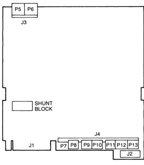
J3
I
SHUNT~_--'. BLOCK
[image:20.615.145.430.92.419.2]J4
Figure 2-4: Connector Location
Figure 2-5: Connector J4 Pin Out
Interface Information 2-7
J4
Pin Description
1 Not Used
2 Not Used
3 NC
4 NC
5 Wrt Protect Switch (Normally Closed)
6 Wrt Protect Switch Common
7
NC8 NC
9 NC
10 Activity LED Signal Cathode
11 Activity LED + V Anode
12 NC
13 NC
14 Index
+
V LED Cathode15 Index Signal Detector Emitter
16 Index Detector Collector
17 GND
18 NC
19 Not Used
20 Not Used
21 NC
22 GND
23 04 24 02
25 01 26 03 27 GND
28 N Motor On
29 NC
30 Motor GND
31 Motor Power
10
2-8 Interface Information
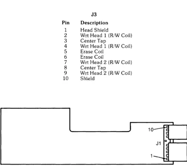
J3
Pin Description
1 Head Shield
2 Wrt Head 1 (R/W Coil)
3 Center Tap
4 Wrt Head 1 (R/W Coil)
5 Erase Coil
6 Erase Coil
7 Wrt Head 2 (R/W Coil)
8 Center Tap
9 Wrt Head 2 (R/W Coil)
10 Shield
J
10--Figure 2-7: Servo Electronics Board Jl
Pin Description
1 + Tach
2 - Tach
3 + Motor Power
4 Motor Return
5 NC 6 NC
7 N Motor On
8 NC 9 GND
10 + 12V
Typical Interface Drive/Receiver Circuits
The output control lines have the following electrical specifications: True = Logical Zero = Vout
+
O.4V (max.) @ lout 48ma (MAX) False = Logical One=
Vout+
2.4V (min.) lout 250ma (max.)J1
1~
I
~ ~
a I I ~
~
~
[image:22.615.100.484.72.415.2]--Interface Information 2-9
DRIVER RECEIVER
- - - ,
I
INTERFACEI74160R EQUIVALENT BUS 74LS040R EQUIVALENT _ _ _ _ _ -' 10 FEET L
MAX
Chapter
3
Theory of Operation
Introduction
This chapter describes the flexible disc recording fundamentals, and functional block dia-gram theory of operation. Refer to Figures 3-1 through 3-3 while reading the following description.
Flexible Disc Recording Fundamentals
To better understand the operation of the flexible disc drive, read this brief description of disc recording principles. Refer to Figure 3-1 and 3-2 while reading this section.
The flexible magnetic media used with the 9130K disc drive measures 5.25 inches in diameter. Both surfaces are coated with a ferromagnetic iron oxide. Both sides are used for data storage. Each side contains 35 circular tracks. Each track is divided into 16 pie slice shaped regions called sectors. Each sector can contain up to 256 bytes of data. Surface, track and sector information is used to reference data location on the disc. Data is encoded on the disc (ones and zeros) by changing the orientation of small magnetic dipoles in the magnetic coating on the disc. There is no correlation between the magnetic polarity of the dipoles and the ones and zeros. The ones and zeros are indicated by the location of the dipole polarity transitions.
The disc is soft sectored, that is, there is no hardware indication of where each sector begins. In order to allow soft sectoring, each sector is divided into two fields. For each sector there is an ID field which contains information to identify the sector. Next there is a data field which contains the actual data. Thus, the ID field serves as a fixed marker for the beginning of each sector.
",..
, /
, /
--- ---
3-2 Theory of Operation
The makeup of the ID and DATA fields is similar. Both fields begin with a series of synchro-nization bytes. These bytes allow the decoder circuitry of the controller time to synchronize itself with the data on the disc. Following the synchronizing bytes, is the address mark byte which indicates that the beginning of an ID or DATA field has been located. The first bit of an address mark is the opposite polarity of the last bit of the previous synchronizing byte. This feature simplifies detection of address marks.
A series of information bytes follows the address mark. In an ID field, these bytes indicate the logical cylinder, head and sector address. In a DATA field, these bytes are the data being stored in the sector.
At the end of each field are two cyclic redundance check (CRC) bytes. This check word (16 bits long) allows detection of most errors that occur in the data storage and recovery of information from a disc.
There are two gaps following each field on a track. The gaps allow for variations in disc rotational speed, index detector alignment variations and time for the hardware to prepare for the next field.
The logical sectors are numbered consecutively. However, the sectors (see Figure 3-2) may occur in any physical order around the track. This allows the sectors to be staggered to optimize system performance (interleaving).
The outermost track on the disc is track 0 and the innermost track is track 34. Each track has a physical address as described preViously. There is also a logical track address associated with each good track. The logical track address is written in the ID field of each sector on the track. If a flexible disc has no bad tracks, the logical track has the same address as the physical track.
The recording head (see Figure 3-3) is moved in and out by a stepper motor assembly. Write current passes through the head coil to selectively magnetize the portions of the disc. To read back data, the magnetized material is passed under the head, thereby indUcing read current into the head coil.
35 concentric tracks on each side (2 are reserved)
Addressable sectors: 16 sectors 33 tracks
Sector numbers (16 total)
- - x ~~-x 2 sides = 1056 sectors track side
Theory of Operation 3-3
Figure 3-3: Head Positioning Assembly
Index Pulse Shaping Network
The index pulse circuitry consists of an index LED, photo transistor and pulse shaping network. The index hole in the flexible disc passes between the index LED and photo transistor, causing the photo transistor to conduct. The detected signal is then shaped and buffered and output on the Index Pulse interface line (J 1-8). This signal although inverted may be observed at TP7 on the drive electronics board.
Write Protect Sensor
The write protect sensor consists of a switch which is opened when a write protected disc is inserted into the drive. This signal is delayed by an RF filter to eliminate transient noise from the switch. This will cause the write protect line (Jl-28) to go low and TP9 to go high.
Track 0 Switch
The level on the Track 0 interface line is a function of the head assembly position. When the head assembly is positioned at track 0 and the stepper motor indicates phase 0, J4-19 is pulled low, causing TP8 and the Track 0 interface line to be pulled low.
Spindle Motor Drive Control
The spindle drive system consists of a spindle assembly driven by a DC motor-tachometer combination and the servo electronics board.
3-4 Theory of Operation
When the Drive Motor Enable line is low, the drive motor is allowed to come up to speed. This speed is adjustable by potentiometer R4 located on the servo electronics board. A current sensing resistor, also located on the servo electronics board limits the motor current to 900ma. If this limit is exceeded, the motor is disabled.
Head Position Control
The head position Control consists of a four phase stepper motor drive which changes one phase for each track advancement of the head assembly. In addition to the logic for motion control, a gate is provided to inhibit repositioning during a write operation.
Power On Circuit
This circuit detects when the +5VDC and + 12VDC are valid and prevents writing/reading/ erasing/stepping until such time.
Data Circuitry
All signals required to control the data circuitry are provided by the host system and are shown in the functional block diagram of Figure 3-4. These signals are as follows:
Drive Select Write Enable Write Data Side Select
There are 4 drive select lines connected to the data electronics. A shunt block determines the drive number. The drive number is established by clipping three of the jumpers on the shunt block or adding a shunt to an empty block. When the selected drive select line is pulled low, the data circuitry is enabled and the drive is conditioned to respond to step or read/write commands.
Writing Data
The write electronics consists of the following circuits: Write/erase current source
Waveform generator Trim erase current source Head select logic
Bias Source
The read/write winding on the head is center tapped. During a write operation, the current from the write current source flows in the alternate halves of the winding under the control of the write waveform generator.
Before recording can begin, certain conditions must be satisfied. The conditions required before writing (i. e., unit ready) must be established by the host system as follows:
1. Drive speed stabilization. This will exist 250ms after starting the drive motor.
INDEX
PULSE ~
INDEX PULSE SHAPING NETWORK INDEX EMITTER and DETECTOR
WRITE WRITE FLEXIBLE
PROTECT ~ PROTECT ~ - - - -... DISC
TRACK 00 DIRECTION STEP WRITE DATA DRIVE SELECT WRITE ENABLE SIDE SELECT READ DATA DRIVE MOTOR ENABLE ~
-
---~ ~ ~ ---+ SWITCHTRACK POWER
00 ON
SWITCH CIRCUIT
,
HEAD DC
POSITION STEPPER
CONTROL MOTOR
tWRITE BUSY
~
WRITE
CURRENT HEAD
f4---ASSEMBLY SOURCE I+-~ READ AMPLIFIER and DIGITIZER SPINDLE
MOTOR DC DRIVE
DRIVE MOTOR
CONTROL
f
SERVO ELEC. BOARD HEAD BIASFigure 3-4: 9130K Functional Block Diagram
Theory of Operation 3-5
3-6 Theory of Operation
The following operations are performed when writing data. These operations may be over-lapped if required.
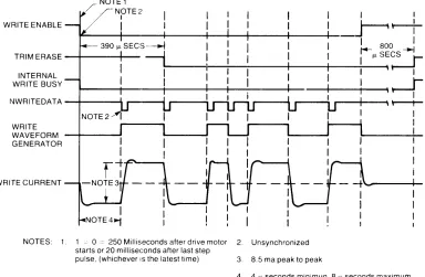
Figure 3-5 shows the rei event timing diagram for a write operation. At T = 0 when the unit is ready, the write enable line goes low. This enables the write current source and bias circuit-ry.
Since the trim erase gaps are behind the read/write gap, the TRIM ERASE control goes true 390 f.1sec. after the WRITE ENABLE interface line. It should be noted that this value is optimized between the requirements at Track 0 and Track 34 so that the effect of the trim erase gaps on previous information is minimized.
Figure 3-5 shows the information on the WRITE DATA interface line, and the output of the Write Waveform Generator which toggles on the leading edge of every WRITE DATA pulse. At the end of recording, at least one additional pulse on the WRITE DATA line must be inserted after the last significant WRITE DATA pulse to avoid excessive peak shift effects. The TRIM ERASE signal must remain true for 800 f.1sec. after the termination of WRITE ENABLE to ensure that all recorded data are trim erased. This value is again optimized between the requirements at Tracks 0 and 34.
The duration of a write operation is from the true-going edge of WRITE ENABLE to the false-going edge of TRIM ERASE. This is indicated by the internal WRITE BUSY waveform shown.
WRITE ENABLE
NOTE1 NOTE2
I I
I I
~~
~--+----+----+----1~-+----+----+-. . I 800 ITRIM ERASE - t - - - - + - - ~ I fJ. SECS --I
r-INTERNALWRITE BUSY
~--+-~-~--+---+--~I-~'~ f - - - - t - - - - + - - - - i - - - - 1 t - - - i - -
--+---...,ll--~\ ~
NWR ITEDAT A - t - - - l i
r---r
WRITE
WAVEFORM - t - - -...
GENERATOR WRITE CURRENT
NOTES: 1. 1 ~ a = 250 Milliseconds after drive motor 2. Unsynchronized starts or 20 milliseconds after last step
pulse, (whichever IS the latest time) 3. 8.5 ma peak to peak
[image:30.611.95.479.437.688.2]4. 4 fJ. seconds minimun. 8 fJ. seconds maximum
Figure 3-5: Write Timing Diagram
Theory of Operation 3-7
Reading Data
The read electronics consists of the following circuitry: Read switch/side select
Read amplifier Filter
Differentiator
a
Crossing detectorThe read swi.tch is used to isolate the read amplifier from the voltage excursion across the magnetic head during a write operation. The side select is used to enable one of the read/write/ erase heads.
Before reading can begin, the Drive must be in a ready condition. As with the data recording operation, this ready condition must be established by the host system. In addition to the requirements established for data recording a 100 f..lsec. delay must exist from the trailing edge of the TRIM ERASE signal to allow the read amplifier to settle after the transient caused by the read switch returning to the Read mode.
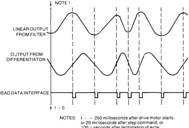
Referring to Figure 3-6, the output signal from the read/write head is amplified by a read amplifier and filtered to remove noise by a linear phase filter. The linear output from the filter is passed to the differentiator which generates a waveform whose zero crossovers correspond to the peaks of the read signal. This signal is then fed to the comparator and digitizer circuit.
The comparator and digitizer circuitry generates a 1 f..lsec. READ DATA pulse corresponding to each peak of the read signal. This composite read data signal is then sent to the host system via the READ DATA interface line.
LINEAR OUTPUT FROM FILTER OUTPUT FROM DIFFERENTIATOR
I I I
I I
I I
~! ~
~
I II I
READ DATA INTERFACE ~-... ,...----11 r----~
I I
r - - - ;
+ t = 0
[image:31.614.161.468.480.688.2]NOTES: t = = 250 milliseconds after drive motor starts, or 20 milliseconds after step command, or 100 fl seconds after termination of write busy, (whichever is the latest time)
Chapter
4
Assembly Access
Introduction
This chapter provides assembly access procedures for the 9130K Flexible Disc Drive. An exploded view is included in this section with disassembly procedures. The disassembly procedures are provided for only those parts considered field replaceable. These parts are as follows:
Drive Electronics Assembly Servo Electronics Assembly Latch and Front Panel Assembly Servo Motor
Media Lift Inhibitor Drive Belt
Activity LED
Index Emitter/Detector Assernbly
WARNING
REMOVE POWER TO THE DISC DRIVE BEFORE REMOVING ANY ASSEMBLY.
NOTE
Unless otherwise noted in the procedures, the disc drive assemb-lies are installed by reversing the procedures given for their re-moval.
The following tools are required to disassemble and reassemble the disc drive:
# 1 Posidriv Screwdriver #2 Posidriv Screwdriver Needlenose Pliers
4-2 Assembly Access
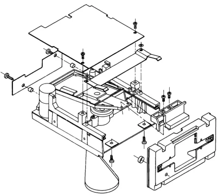
Figure 4-1: 9130K Flexible Disc Drive Exploded View
To access the internal assemblies, the drive electronics board Al must first be removed. To do this, refer to Figure 4-2 and disconnect connectors P5, P6 and P8 through P13. Next remove the two screws (A) and slide the board toward the rear of the drive so that the notches in the sides of the board are centered about the two side retainers. Lift the board from the drive and place on a clean dry surface.
B C
Figure 4-2: Drive Board and Servo Board Removal
Assembly Access 4-3
The drive belt is removed by grasping it with the index finger and thumb and rotating the spindle pulley while gently pulling the belt from the bottom of the drive.
The spindle rnotor is removed by removing the two screws (D) from the bottom of the drive. Be careful not to lose the two nylon washers under the screws.
To remove and replace the front panel/latch follow these instructions carefully:
CAUTION
PRIOR TO REMOVING ANY ADDITIONAL HARDWARE, BE SURE TO PLACE A LARGE RUBBER BAND AROUND THE DRIVE UNIT AS SHOWN IN FIGURE 4-3 TO KEEP THE CONE ASSEMBLY IN PLACE. IF THIS IS NOT DONE, THE HEAD RETURN SPRING WILL BE DAMAGED.
Remove the two screws (E) and lift the latch out from behind the front panel.
Next slide the collar from around the activity LED toward the rear of the drive. Slide the LED out of its holder in the front panel. Place the drive on its side and remove the two screws (F) and pull the front panel from the drive unit.
4-4 Assembly Access
[image:35.614.129.458.85.339.2]E
Figure 4-3: Front Panel and Latch Removal
Chapter
5
Maintenance
Introduction
This chapter provides maintenance information for servicing the 9130K flexible disc drive. This information includes failure analysis, alignment and adjustment procedures, required tools, DSU operating instructions and test point locations and waveforms for both the 09130-66501 and 82901-66515 drive boards.
Service Kit Contents
The host product has a two part service kit. Part 1 consists of the 9130K service kit, used to repair the disc drive(s), and part 2 is the product dependent service kit, used to repair the host system.
The contents of the 9130K service kit are as follows:
Part Number 09130-69600 09130-66501 09130-66500 4040-1636 4040-1856 4040-1635 1600-1137 0510-0042 1400-0249 0950-0448 3140-0654 7121-1451 Description
Drive mechanical assembly with servo electronics, HP front panel and grey latch (same as 9130K Opt. 51). Drive electronics board Servo electronics board HP latch, grey
HP latch, brown HP front panel Media lift inhibitor Retaining clip Cable ties Drive belt Spindle motor Strobe label Quantity 1 1 1 2 2 1 1 4 10 4 2 10
The Product Support Package for all versions of the 9130K is as follows:
Part Number Description Quantity
9164-0151 Alignment disc 1
9164-0129 Blank disc 1
60401-0521 Molley cote grease 1
(for latch lubrication)
5-2 Maintenance
There is a 9130K video tape presentation available under HP part number 90362RZ. This tape contains theory of operation, product description and service information on the 9130K.
Drive Failure Analysis
The following possible drive failures and their symptoms are provided to simplify troub-leshooting and repair of the disc drive at the customers site. Included are corrective actions which can be taken to remedy the problems.
Sympton
NOTE
Upon entering a customer's site, carefully examine the conditions under which the flexible disc drive is operating. Also ask to see the customer's media. It is a good possibility that the customer is using non-HP media or the operating environment is too dirty to assure reliable operation. This is especially true when a customer experiences higher than normal soft errors. For these reasons you may have difficulty duplicating the customer's failure. When this occurs, ask the customer to duplicate the failure. If there is a high soft error rate problem, closely examine the customer's media for contamination and wear. Be sure to stress proper disc handling and use.
Another important point to be noted is that the 9130K disc drive is not a high duty cycle "Virtual Memory" type device. The 9130K reliability is not linear with its use.
High read error rate
Possible Failure
Media misuse and abuse
Corrective Action
Teach customer proper media use/handling
Drive buzzes or chatters or "bad disc" error
"Missing Disc" errors "Seek" errors
Servo board failure Drive board failure Contaminated heads Heads misaligned Drive board failure
Track 0 switch failure
Replace servo board Replace drive board Clean heads
Align heads/swap drive Replace drive board
Replace drive assembly Index emitter/detector failure Replace emitter/detector pair
Drive board failure Replace drive board
Drive belt failure Replace and/or adjust drive
belt Stepper motor failure
Servo board failure Drive motor failure
Index emitter/detector mis-aligned
Disc latched off center when inserted into drive
Replace drive Replace servo board Replace drive motor
Align index emitter/detector pair
Maintenance 5-3
Head Cleaning
Periodically the read/write heads on the 9130K may require cleaning. This is especially true
if media failure has been detected. The HP PIN for the head cleaning kit is 92193A.
A mainframe dependent clean program is required to effectively clean the heads and also to efficiently utilize the entire cleaning disc surface.
Termination Resistor IC U2F (09130-66501 only)
This resistor IC (150
n
per resistor) is inserted into the last drive of a daisy chain. Remem-ber to insert this resistor IC into the replacement drive when servicing the last drive on a daisy chain.Shunt Block
UIE
(09130-66501 only)
The shunt block must be configured on a replacement drive as it is on the drive being removed.
Alignment and Adjustments
Introduction
This section provides the adjustment procedures for the 9130K flexible disc drive. The following recommended adjustments are relatively easy to perform and may be done at the customers location. The "E" number following the "TP" number is for the 82901-66515 drive boards only.
• Spindle motor sp~ed adjustment • Spindle drive belt adjustment
Spindle Motor Speed Adjustment
The spindle motor speed should be re-adjusted whenever a new spindle motor or servo electronics board is installed. Refer to Figure 5-1 while making this adjustment.
Required Tools:
• Alignment tool or small insulated shank screwdriver
• HP 5314A or eqUivalent frequency counter (if primary power frequency is unknown or unstable or when adjusting motor speed under incandescent lighting).
Follow these instructions when primary power is a known 50 or 60 Hz and you are making this adjustment under flourescent lighting.
1. Check the spindle pulley to see that it has a strobe label. If not, use one from your service kit.
2. Turn the spindle motor power on and observe the strobe pattern on the spindle pulley. For 50Hz primary power observe inner pattern. For 60Hz, observe the outer pattern.
5-4 Maintenance
If the primary power frequency is unstable or unknown, follow these instructions:
1. Connect the frequency counter input to TP7/E7 (index) and (TP6/Ell ground). 2. Turn the spindle motor on.
3. Locate and adjust the potentiometer on the servo board until a 200ms
+
1-1 % period is observed on the counter display. This will assure a 300 RPM spindle speed.CAUTION
USE AN INSULATED SHANK FLAT BLADE SCREWDRIVER OR ALIGNMENT TOOL TO AVOID SHORTING OF THE TRAN-SISTOR LEADS ON THE TANDON DESIGN SERVO BOARD.
1
0
1~
pJ. )
-9130-66500
SPEED ADJUST POTENTIOMETER
/
TANDON BOARD
[image:39.614.93.481.267.586.2]J
Figure 5-1: Spindle Motor Speed Adjustment
Spindle Drive Belt Adjustment
Maintenance 5-5
Required Tools:
• # 1 posidriv screwdriver
• Spindle motor adjustment tool PIN 8710-1385
Refer to Figure 5-2 while performing these steps:
1. Place the drive assembly on its side so that the bottom of the drive faces you. 2. Remove the drive belt.
3. Place the spindle motor adjustment tool on the bottom of the drive as shown in Figure 5-2 so that the smallend of the adjustment tool rests against the motor pulley and the large end rests against the spindle pulley.
4. Slightly loosen the spindle motor retaining screws and move the motor until it rests firmly against the adjustment tool.
5. Re-tighten the spindle motor retaining screws and reinstall the drive belt.
NOTE
[image:40.612.124.527.374.706.2]There is a good chance that the drive motor is not exactly perpen-dicular to the drive casting on which it is mounted. This will cause the drive belt to slip from the drive pulley when it is rotated. After a belt is installed, rotate the drive spindle approximately 10 re-volutions to insure the belt will not slip from the drive pulley.
5-6 Maintenance
The following adjustments should not be performed except in emergency situations due to their delicate nature. These adjustments are never to be performed at the customers loca-tion.
The adjustments described in this section are: • Radial Head Alignment
• Head Azimuth Adjustment • Track 0 Switch Adjustment
• Index Emitter/Detector Adjustment • Write Protect Switch Adjustment
Required Tools and Test Equipment
Oscilloscope
Dual Power Supply (+5VDC and + 12VDC) Disc Service Unit (DSU)
DSU Adapter Cable Alignment Disc Torque Driver
# 1 Posidriv Screwdriver #2 Posidriv Screwdriver
3/16 Thin Wall Nutdriver
HP 1740A or equivalent
HP 6253A or equivalent
PIN 12748-60006 or equivalent
PIN 09130-61606 or equivalent
PIN 9164-0151 PIN 8710-0670 PIN 8710-0899 PIN 8710-0900 PIN 8720-0001
[image:41.611.104.473.439.675.2]The 9130K flexible disc drive must have power applied and the DSU and adapter connected to perform the following adjustments (refer to Figure 5-3). do not power the DSU with the host systems
+
5 VDC supply or damage to the host system may result.Maintenance 5-7
Radial Head Alignment
To properly align the read/write heads, perform to the following steps in the order shown. Refer to the troubleshooting section for head misalignment symptoms.
1. Connect the equipment as shown in Figure 5-3 and apply power.
2. If the DSU display reads "bAd" or if TRK 0 LED indicator on the DSU is not lit, depress the SYSTEM RESET pushbutton on the DSU.
3. Insert Alignment disc PiN 9164-0151 into the drive and close the latch. 4. Connect and setup the scope as follows:
Connect channel A to TP7/E7 (INDEX) and ground lead to TP6/El1. Connect channel B to TP4/E4 (READ DATA) and ground lead to TP6/El1. Trigger:
Display: Volts/DIV: Time/DIV:
Internal on channel A (POS) Channel B
.2V/DIV (using a 10: 1 probe) 20ms/DIV
5. With the scope connected, the pattern shown in Figure 5-4 should be observed. 6. Both lobes of the pattern should be equal in amplitude.
Figure 5-4: Radial Head Alignment Waveform
5-8 Maintenance
Figure 5-5: Head Assembly Retaining Screws
8. After the radial head alignment has been completed, re-tighten the three screws loosened in step 7 while observing the scope pattern. Tighten the retaining screws with the torque-driver set at 8 inch pounds.
Head Azimuth Alignment
The head azimuth is not field adjustable due to its very delicate nature. For this reason, the drive unit should be returned to CSD for azimuth alignment. To determine whether the head azimuth is out of limits, perform the following procedures:
Connect channel A of the scope to TP4/E4 and ground lead to TPIO/EIL Connect channel B to TP7/E7 and ground lead to TP6/EIL
Setup the scope as follows:
Trigger: Internal on channel B (pas)
Display: Channel A Volts/DIV: .02V/DIV Time/DIV: Ims/DIV
Maintenance 5-9
Figure 5-6: Head Azimuth Waveform
Track 0 Switch Adjustment (extremely difficult adjustment)
Track 0 switch adjustment should be performed whenever the radial head alignment is changed. To properly adjust the track 0 switch, follow these steps in the order shown:
1. Connect the equipment as shown in Figure 5-3.
2. Disconnect connectors P5 and P6 from the front of the drive board.
3. Remove the drive board retaining screws and carefully lift the drive board from the drive assembly.
4. Slightly loosen the track 0 switch retaining screw shown in Figure 5- 7.
[image:44.612.228.406.496.698.2]5-10
MaintenanceS. Rest the drive board on a piece of insulating material, such as cardboard, on top of the drive assembly.
6. Setup the DSU as follows: MAX TRACK: 4 MIN TRACK: 0
STEP RATE: Sms/track (Alternate Seek) 7. Connect and setup the oscilloscope as follows:
Connect channel A to TP12/US-S and (STEP) and ground lead to TP10/E11. Connect channel B to U4F pin 11/U1 pin 11 and ground lead to TP6/E11. Trigger:
Display: Volts/DIV: Time/DIV:
Internal on channel A (paS) Channel B
.02V/DIV (using a 10: 1 probe) 1ms/DIV
8. With the scope connected and setup, the pattern should be similar to that of Figure S-8. The duration of the pulse from TO to T1 must be lSms or less time TO to T2 20ms or less.
Figure 5-8: Track 0 Waveform
9. With the torque driver adjusted to 8 inch pounds, re-tighten the track 0 switch retain-ing screw while observretain-ing the oscilloscope pattern.
10. Reinstall the drive board and connectors PS and P6. Tighten the board retaining screws with the torque driver set to 8 inch pounds.
Index Emitter/Detector Adjustment
Follow thes€~ steps in the order shown:
[image:46.612.190.449.149.362.2]1. Place the drive assembly on its side with the bottom facing you. 2. Connect the equipment as shown in Figure 5-3.
Figure 5-9: Index Detector Retaining Screw
4. Insert alignment disc into the drive and close the latch. 5. Seek to track 16, head O.
6. Apply power and start the drive motor.
7. Connect and setup the oscilloscope as follows:
Connect channel A to TP7/E7 (INDEX) and ground lead to TP6/E11.
Conn€~ct channel B to TP1/E1 (READ DATA) and ground TP10/E11. Trigger:
Display: Volts/DIV: Time/DIV:
Internal on channel A (POS) Channel B
.02V/DIV (using 10: 1 probe)
.1ms/DIV
8. The oscilloscope presentation should look like that of Figure 5-10.
Maintenance 5-11
9. Loosen the index detector retaining screw (Figure 5-9) and move the detector until the INDEX to DATA burst time is approximately 400 f..LS
+
I - 300 f..LS for head O. 10. Re-tighten the index detector retaining screw using the torque driver set to 8 inchpounds while observing the scope.
11. Check the INDEX to DATA time for head 1 by depressing and releasing the SELECT HEAD 1 pushbutton switch on the DSU.
12. If the INDEX to DATA time is too far out, adjust the index emitter located on the top side of the drive assembly and then re-do steps 9 through 11.
13. Tighten the index emitter and detector retaining screws using the torque driver set to 8 inch pounds.
5-12 Maintenance
Figure 5-10. Index to Burst Waveform
Write Protect Switch Adjustment
The disc drive head assembly may be severely damaged while performing this adjustment. For this reason, replacement or adjustment of this switch is not to be done in the field.
Read/Write Test
A read/write test may be performed to verify proper operation of the read/write circuitry on the 9130K drive. Perform the following steps in the order shown:
1. Connect the equipment as shown in Figure 5-3.
2. Insert a test disc (not the alignment disc) into the drive and close the latch. 3. Connect and setup the oscilloscope as follows:
Connect channel A to TP4/E4 (READ DATA) and ground lead to TP6/E11. Connect channel B to TP7/E7 (INDEX) and ground lead to TP10/E11. Trigger:
Display: Volts/DIV: Time/DIV:
Internal on channel a (POS) Channel B
.05V/DIV (using 10: 1 probe) 5/-1s/DIV
4. Apply power and depress and release the DRIVE VALIDATE, MOTOR ON and WRITE IF & 2F WRITE ENABLE pushbuttons ON the DSU.
5. Depress and release the DWRITE IF pushbutton and observe the oscilloscope dis-play. The presentation should be like that of Figure 5-11. If the waveform is distorted or if point A and point B overlap, there is a problem in the read or write circuit. 6. Depress and release the WRITE 2F pushbutton and again observe the scope display.
Maintenance 5-13
Figure 5-11: Write IF Waveform
Figure 5-12: Write 2F Waveform
7. If the waveform appears normal, remove power and disconnect the test equipment. If
not, replace the drive board.
DSU Controls and Indicators
5-14 Maintenance
DSU to the 9130K. The Disc Service Unit and adapter cable both require a +5V supply. The 9130K also requires a +5V and + 12V supply. Therefore a dual power supply (+5V and + 12V) should be used. This information is for reference only. Most mainframes can function in place of DSU.
The front panel of the DSU with the overlay installed, is shown in Figure 5-13 .
•
1•
\} !'"
II II}I 2; 3 '
{)
[image:49.614.146.433.181.405.2]~
Figure 5-13: DSU Controls and Indicators
The DSU LED descriptions are as follows:
INDEX LED Lights each time index hole in disc passes the disc drive index sensor.
RD/WR DATA DRIVE READY TRKO
WRITE PROTECT
Lights when DSU is writing on or reading from a disc. Lights when the disc drive is ready to be exercised. Indicates when the read/write head is at track O. Indicates when the disc is write protected. The DSU switch functions are follows:
KEYPAD
STOP
Used to establish parameter values for min and max track and step rate. Each time a key is pressed, that number is entered into least significant digit of 3-digit decimal display and other numbers shift up. The programmed number is entered when appropriate parameter pushbutton is press-ed.
SYSTEM RESET
DRIVE SELECT VALIDATE
SELECT HD 1
MOTOR ON
IF & 2F WRITE ENABLE
WRITE IF
WRITE 6J..ls DIPULSE
WRITE 2F
WRITE 3J..ls DIPULSE
Maintenance 5-15
Resets the entire system and disc drive. DSU self test is initiated and the disc drive is recalibrated and initialized. Validates drive number. Pushbutton indicator lights when drive number is valid.
Selects read/write head. When indicator is on, head 1 is selected; when indicator is off, head 0 is selected. At DSU power-on and reset, head 0 is selected.
Turns spindle motor on and off. Indicator is lit when spin-dle motor is running.
Enables the DSU to write to the disc drive.
Writes l' s (125kHz) on disc. Pushbutton indicator lights when WRITE IF is selected.
Writes 0' s (250kHz) on disc. Pushbutton indicator lights when WRITE 2F is selected.
NOTE
If a write pushbutton is depressed and released in less than 1.5 seconds, the write operation lasts for one complete revolution of the disc. Holding the pushbutton depressed longer than 1.5 seconds produces a continuous write.
MAX TRACK
MIN TRACK
STEP RATE
SEEK TO TRACK
ALT SEEK
Enters keypad number selected for alternate seek max-imum track number. Indicator flashes when number en-tered is less than the current alternate seek minimum track number. At power-on or system reset, the maximum track number is reset to 76.
Enters keypad number selected for alternate seek minimun track number. Indicator flashes when number entered is greater than the current alternate seek maximum track number. At power-on or system reset the minimum track number is reset to O.
Enters keypad number in milliseconds selected for track-to-track seek time. Pushbutton indicator flashes if number is less than 3. At power-on and reset the number is set to 3. Disc drive seeks to track number selected by keypad. If number selected is greater than 34, disc drive seeks to track 34. At power-on and reset, the drive seeks to track 0 automatically and the keypad is reset to O.
5-16 Maintenance
SINGLE STEP IN Head assembly steps inward one track. Pushbutton indica-tor is let when heads are at inner most track.
SINGLE STEP OUT Head assembly steps outward one track. Pushbutton in-dicator flashes if heads are at outer most track (0).
Disc Service Unit Operation
This section provides the operating instructions for the Disc Service Unit (DSU).
CAUTION
THE DSU WAS ORIGINALLY DESIGNED TO SERVICE AN 8 INCH FLEXIBLE DISC DRIVE, THEREFORE, CERTAIN PRE-CAUTIONS MUST BE TAKEN WHEN EXERCISING THE 9130K WITH THE DSU. AT POWER-ON AND SYSTEM RESET, THE DEFAULT MAX TRACK PARAMETER IS SET TO 76. THIS PA-RAMETER MUST BE MANUALLY RESET TO 34 TO PREVENT ACCIDENTAL DAMAGE TO THE HEAD POSITIONING ASSEMBLY. ALSO CAUTION MUST BE TAKEN WHEN SING-LE STEPPING THE HEAD ASSEMBLY SO AS NOT TO EXCEED THE INNER LIMIT OF THE DRIVE (34th TRACK).
Perform the following steps in the order shown to properly operate the 9130K flexible disc drive:
[image:51.612.84.487.424.689.2]1. Remove all power prior to connecting the DSU, adapter cable and disc drive. 2. Connect the equipment as shown in Figure 5-14.
Maintenance 5-17
3. Apply power to the system. The DSU and adapter cable require +5VDC while the disc drive requires both +5VDC and + 12VDC. A dual power supply capable of outputting +5VDC and + 12VDC at 2ADC minimum is recommended.
4. Upon applying power, the DSU self test is initiated. This is evident by the three 8's seen on the DSU display. During the DSU self test, the drive motor will run. If the DSU self test fails, the DSU display will read "bAd". Re-initiate the self test by depressing the SYSTEM RESET pushbutton on the DSU. When the DSU has passed the self test, the DSU display will read "000" and the drive motor will stop. At this time the TRK 0, Drive Ready and RDIWR DATA LED's should be lit. If a write protected disc has been inserted into the drive, the WRITE PROTECTED LED will be lit.
5. Depress the DRIVE VALIDATE pushbutton (the drive is selected when the DRIVE VALIDATE pushbutton indicator is lit). The remaining DSU functions are now en-abled by depressing the selected pushbuttons.
Packaging Instructions
The following instructions are provided to ensure proper packaging for safe shipment of the 9130K flexible disc drive assembly (less drive electronics board).
The following materials are required to package the drive assembly:
Description
I-Outer Box I-Inner Box I-Foam Pac
I-Foam Latch Insert 2-Foam End Caps
HP Part Number
9211-3595 9211-3594 4208-0368 9220-3448 9220-3450
To ensure damage free shipment of the 9130K drive assembly, follow these instructions: 1. Remove and retain the drive electronics board fastened to the top of the drive. 2. Open the front latch and insert the foam latch insert (PIN 9220-3448) as shown in
Figure 5-1:5.
5-18 Maintenance
[image:53.612.120.453.394.643.2]3. Place the foam pad (PIN 4208-0368) on top of the drive assembly and insert into the inner box (PIN 9211-3594) as shown in Figure 5-16.
Figure 5-16: Inner Box
4. Refer to Figure 5-1 7 and close the inner box and insert into the two foam end caps (PIN 9220-3450).
Figure 5-17: Foam End Caps
Maintenance 5-19
Figure 5-18: Outer Box
Test Point Location and Waveforms
(PIN 09130-66501)
This section provides test point location and waveforms which can be observed at these points. To reproduce these waveforms, alignment disc PIN 9164-0151 must be used. The oscilloscope settings for each waveform is shown for each waveform.
TP12·
TP11·
TP5· TP7·
TP2·
TP4· TP10. TP1. TP3.
TPS·
.TP13
5-20 Maintenance
Ea-
_ E9E7- - E6
E11E2
-
E10-
E3-- E4
E5
[image:55.611.165.410.106.371.2]-r-ca--;:::::::;-;;::::::::;:::=~H:::::::::;:===;:::::=:::!
Figure 5-20: Test Point Locations (82901-66515)
TPI/TP2 (EI/E2) READ DATA (ANALOG) Volts/DIV: .005V/DIV
TP3/TP4 (E3/E4) DIFFERENTIATED READ DATA (ANALOG) Volts/DIV: .01 V/DIV
Time/DIV: 10ms/DIV
TP5 (E5) READ DATA (DIGITAL) Volts/DIV: 1 V/DIV
Time/DIV: 5us/DIV
TP6 (Ell) GROUND
5-22 Maintenance
TP7 (E7) INDEX Volts/DIV: .1 V/DIV Time/DIV: 1ms/DIV
TP8 (E9) TRACK 0 Volts/DIV: 2V/DIV Time/DIV: 10ms/DIV
TP9 (E8) WRITE PROTECT Volts/DIV: 1 V/DIV
Time/DIV: lOms/DIV
Inserting disc gives positive transition Removing disc gives negative transition
TPIO (EIO) GROUND
TPll DRIVE SELECT
TP12 (U5-5) STEP Volts/DIV: .2V/DIV
Time/DIV: lus/DIV
NO WAVEFORM
5-24 Maintenance
TP13 MOTOR ON
Volts/DIV: .1 V/DIV
Time/DIV: 10ms/DIV
Motor on gives negative transition Motor off gives positive transition
NOTE