Systems Reference Library
IBM 1622 Card Read-Punch
This manual describes the operation of the 1622 Card Read-Punch, Models 1 and 2, as they are used in the 1620 Data Processing System, Models 1 and 2, and in the 1710 Control System.
This manual has been extracted from and supersedes the publication IBM 1620 Input/Output Units (Form A26-5707). Input/Output instructions for the 1622 are described in either 1620 Central Processing Unit, Model
1 (A26-5706) or 1620 Central Processing Unit, Model 2
(A26-5781). The Paper Tape Unit is described in the publication 1621 Paper Tape Unit (A26-5836).
Copies of this and other IBM publications can be obtained through IBM Branch Offices. Comments concerning the contents of this publication may be a.ddressed to:
IBM, Product Publications Department, San Jose, Calif. 95114
1622 Card Read-Punch
The IBM Card Field Definition
Card Reading Card Punching
Card Coding . . . . Double Punch Detection . . . . BCD Coded Data . . . . Operator Keys and Lights
Card Reader . . . .
Page 1
1
3
3
5 5
6 6
7 7
Contents
Card Punch . . . . Page
8 8
Card Reader/Punch Lights Error Restart Procedures
Reader Check Error 1620 Read Check Error Punch Check Error . . . 1620 Write Check Error
Appendix A . . . .
Character Coding Chart
9
9
9 9 9
10
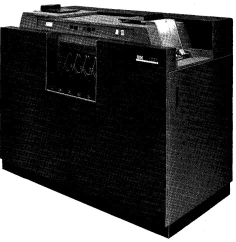
The IBM 1622 Card Read-Punch (Figure 1) provides punched card input and output for the system. The reader and punch feeds are separate and functionally independent, with individual switches, lights, check-ing circuits, buffer storage, and instruction codes.
The Modell reads and punches at a rate of 250 and 125 cards per minute; the Model 2 reads and punches at a rate of 500 and 250 cards per minute. The programming and operating features of both models are identical.
Reading, punching, and processing can occur simul-taneously because of individual buffer storage. Buffer
[image:5.613.317.553.199.554.2] [image:5.613.66.302.440.682.2]storage data is transferred in 3.4 ms in the 1620 Modell System and in 1.7 ms in the 1620 Model 2 System (Figure 2).
Figure 1. IBM 1622 Card Read-Punch
1622 Card Read-Punch
(
Punch(
Read 125 or 250 250 or 500 cards per minute cards per minuteOutput Buffer Input Buffer
~
Core Storage
Figure 2. 1622 Buffer Storage
The IBM Card
The IBM card measures 7-3/8 inches by 3-1/4 inches
and is .007 inches in thickness. The card stock is of controlled quality, manufactured according to rigor-ous specifications in order to provide strength and long life. This is necessary to ensure the accuracy of results, the proper operation of IBM data processing machines, and the continued usability of information long after it is recorded.
column is then divided horizontally into 12 punching positions. Thus the IBM card has 960 punching posi-tions in all. The punching posiposi-tions are designated, from top to botton of the card, 12, 11 or X, 0, 1, 2, 3, 4, 5, 6, 7, 8 and 9. The punching positions for digits
o
to 9 correspond to the numbers printed on the card. The top of the card is known as the "12 edge" and the bottom as the "9 edge." These designations are made because cards are fed through machines either "9 edge first" or "12 edge first." "Face up" means the printed side is facing up; "face down," the reverse.Each column of the card is able to accommodate a digit, a letter, or a special character. Thus the card may contain up to 80 individual places of informa-tion. Digits are recorded by holes punched in the digit punching area of the card from 0 to 9. For ex-ample, the card in Figure 3 shows a 1 punched in col-umn 63, a 9 in colcol-umn 72, and a 4 in colcol-umn 77.
The top three punching positions of the card (12, 11 or X, and 0) are known as the zone punching area of the card. (It should be noted that the 0 punch may be either a zone punch or a digit punch.) In order to accommodate any of the 26 letters in one column, a combination of a zone punch and a digit punch is
used. The various combinations of punches which represent the alphabet are based upon a logical struc-ture or code.
The first nine letters of the alphabet, A to I, are coded by the combination of a 12 punch and digit punches 1 to 9. Letters
J
through R are coded by an 11 or X punch and digit punches 1 through 9. S through Z, the last eight letters, are the combination of the 0 zone punch and digit punches 2 through 9. Figure 4 illustrates alphabetic coding. The conversion of letters to and from this coding structure i~ done automatically by the various machines used to record or process data and it is rarely necessary to refer to data in its coded form. The 11 special characters, which are considered alphameric data, 'are recorded by one, two, or three punches.Figures 3 and 4 illustrate the two most common types of comer cuts - upper left and upper right. The corner cut is used to identify visually a card type or to ensure that all the cards in a group are facing the same direction and are right side up. Card types may also be distinguished by the use of colored cards or by a colored stripe on cards of a similar nature.
r---~::,.;_r~_eu_~
_____c_~_~_~_n
______rT_h_e_~_~i_~_~_~_h_in_9J
______________________________________________ --,~' The "12 Edge" of the Cam
I 12 Punch A 1 Punched in A 4 Punched
I h Column 63 in Column 77
o 0 0 0 0 0 0 0 0 0 0 0 0 0 0 0 0 0 0 0 0 0 10 0.0 0 0 0 0 0 0 0 0 0 0 0 0 0 0 0 0 0 0 0 0 0 0 0 0 0 0 0 0 0 0 0 0 0 0 0 0 0"0 0 0 0 0 0 0 0 0 0 0 0 0 0 0
11 or X Punc ~
, 2 3 4 5 6 7 8 9 1011 12 13 14 15 16 17 18 19 ZO 212223242526 272829 30 31 3233 34 3~ 36 37 3i 39 40 414243 44 45 46 4148 49'50 51 525354 55 56 57 58 59 60 616 364 55 G& 57 !;8 &3 10 11 72 3747576 11 7~ 79 8C
'1111111111111 t 111111 i 1111111111111111111111111111111111111111 111111111 1111111
2222222222222222222222221222222222222222222222222222 2 2 2222222222222222222 222222
33333333333333333333333331333333333333333333333333333333333333333333333333 33333
44444444444444444444444444144444444444444444444444444444444444444444444444441444
5555555555555555555555555551555555555-555555555555555 5 5 5 5 5 5 5 555555555555555555555
6666666666666666666666666666166666666666666666666666 6 6 6 6 6 6 6 6 6 6 6 6 6 6 6 6 6 6 6 6 6 6 6 6 6 6 6 6
77 7 77 77 7 7 7 7 7 77 7 7 7 77 7 7 7 7 7 7 77 771717177117171 7 7 717 717 77 777777777 7 7 77777777777 7 7 7 777
8888888888888888888888888888881888888888888888988888 8 t8 8 8 8 8888888888888888888888
99999999999999999999999999999991999999999999999999999999999999999999999199999999
1 2 3 4 5 6 7 • , ,0 11 '2 13 '4 15 16 Il " 19 20 21 22 23 24 25 26 27 28 29 30 31 32 33 34 35 36 31 31 3t 40 41 42 43 44 45 4fi 47 48 4. III 51 52 53 54 55 56 (a1 51 51 10 61 52 53 64&HS 67 " 69 70 J1 12 73 14 15 76 77 79 79 10
Column Numbers
t
Card Column12
The "9 Edge" of the Card
;
A 9 Punched in Column 72
Figure 3. IBM Card
[image:6.612.48.536.400.726.2]Upper Right Corner Cut
l
l l l l l l i l l I I IZone
III or X Punch Punches IIIIIII11 I I I
~~~~~~~~~~~~~~!~~~~~~~~~~~~~!O~~~~~~~!~!~~~~~~~~!!~!~!!!~~~!~!!~!~~~!~~~~~~~~~~!
112 Punch111111111111111111111 i l l 1111111111111111111111111111111111111111111111111111111
222222212222222212222222 2222221222222221222222212222222222222222222222222222222
333333313333333331333333 3333333133333333133333331333333333333311113333333333333
44444441444444444414444 44444444414444444414444444144444444444444444411114444444
Digit Punches
55555551555555555551555555555555551555555551555555515555555555555555555~55555555
66666661666666666666166666666666666166666666166666661666666666666666666666666666
77 77 77 7117 77 7 7717 77 77117 77 77 7 7 77 77 7177 7 77 7 7717 17 7 777177 77777 77 777777 1 7 7 77 7 11711
888888818888888888888818 8888888888881888888881888888818888888811118811118888888
99999991999999999999999 9999999999999199999999199999991999999999999999999999999
1234561'9~lluu~~nn~~~~nn2~~n~H»~»~M~»V»~~~~~~~~U.~~~~~M~~~~~~~~~H""~~~ronnn~~nn~~~
Column Numbers
L
Digit .1
Punches---1
+
...
- - - - T h e Alphabet---A+l
Characters Specialj
Figure 4. Card Character CodingField Definition
The fields in a card normally consist of 1 to 80 col-umns of data, depending on the length of the particu-lar type of information. However, a field in 1620 core storage must consist of at least 2 digits or positions.
NUMERICAL DATA FIELD DEFINITION
The high-order column of a field is punched with an 11 punch as well as the digit punch. Thus, the field defining column of a numeric field contains an alpha-meric character (J through R) which becomes a digit with a flag bit when read into core storage by a Read Numerically instruction. (See CHARACTER CODING, APPENDIX A.)
ALPHAMERIC RECORD DEFINITION
The record-defining record mark character must be stored in core storage before or after a Read Alpha-merically instruction is used to read alphameric data into core storage.
As shown in Figure 5, cards are fed from the read hopper on the right and the punch hopper on the left. Each hopper has a capacity of 1,200 cards. Both feeds
have misfeeding and jam detection, and a select and a nons elect stacker. The 1,000-card-capacity stackers are of the radial type: the cards are stacked on end to permit their removal while the 1622 is running.
If either the read or punch feed is not used for ap-proximately one minute, the drive motor for that feed is turned off to reduce noise and wear. However, the 1622 is still in ready status and responsive to a read or write command.
Card Reading'
Cards are fed 9-edge first, face down, past two read-ing stations: check and read. Input buffer storage is initially loaded with 80 columns of card data during the Start key or Load key run-in operation. There-after, each card feed cycle is under program control. Data flow during card reader operation, shown in Figure 6, is as follows:
[image:7.617.57.556.66.339.2]POWER PUNCH READY CHECK PUNCH II
START ~ READY CHIP
FUSE TRANS-PORT
PUNCH
PUNCH CHECK PUNCH STATION STATION HOPi>ER
~
~mCl
o
STATIONFigure 5. 1622 Keys, Lights, and Card Feed
ERROR SELECT STACKER
1622
1620
NON-SELECT STACKER
CIRCLED NUMBERS REFER TO TEXT
INPUT BUFFER STORAGE
Figure 6. Read Operation Data Flow
4
STOP
PUNCH NON-SELECT
READER POWER CHECK READY CHECK II
LOAD ~
8
READERRESET READY
STACKER THERMAL KEYS AND LIGHTS
i
I
READERI
I
I
!
PUNCH READ ERROR NOT USED ERROR SELECT SELECT CARD READER AND PUNCH STACKERS
CHECK STATION
READ NON-SELECT
READ CHECK READER STATION STATION
~
HOPPER~~cct
STATION 0
0
READ
HOPPER
I
®---t::::.-_----.J
o
EQUAL
UNEQUAL
ERROR ISTOP READERI
ERROR
" 1/
-~- READY
/ I"
"~~/
READER-~ - CHECK
/1
1622
1620
I
~ READ
-A---',,-
CHECK1
[image:8.618.42.541.68.720.2]If a parity error occurs during data transfer to the 1620, the 1620 console Read Check light and 06 indicator are turned on. The 06 indi-cator may be used to branch to an error-handling subroutine.
2. Following a correct transfer of data, a card is fed and new data is read into buffer storage. 3. The new data is compared at the read station
against stored data previously read at the check station.
An unequal comparison between check and read stations, or a 1622 parity error stops the reader, turns on the 1622 Reader Check light, and terminates ready status. No data transfer to the 1620 is permitted. The Reader Check light therefore cannot be on simultaneously with the 1620 Read Check light.
4. At the same time that new data is read at the read station (Step 2), data on the card follow-ing is read at the check station and stored for comparison on the next card feed cycle.
Card
Punching
Cards are fed 12-edge first, face down, past the punch and check stations. Data How during the card punch operation shown in Figure 7, is as follows:
1. A write command causes a data transfer from core storage to output buffer storage. The transferred data is parity-checked in the 1620; if parity is correct, a card feed cycle follows immediately to punch the data into the card from buffer storage. The data is also parity-checked in the 1622 as it is punched into the card.
If a parity error occurs during data transfer, the 1620 console Write Check light and 07 in-dicator are turned on. The 07 inin-dicator may be used. to branch to an error-handling sub-routine.
2. Following a correct transfer, the data is stored for comparing (Step 3) , punched into the card, and parity-checked.
If a 1622 parity error occurs, a cycle delay is initiated and the punch is stopped one card feed cycle after punching the incorrect data (Select Stop switch set to STOP). The 1622
Punch Check light is turned on and ready status is terminated.
3. The card punched in Step 2 is read at the check station one cycle later and compared with the data stored in Step 2. An unequal comparison has the same effect as a 1622 parity error: the punch is stopped after the
card cycle on which the unequal comparison occurred (nocycle delay), the Punch Check light is turned on, and ready status is termi-nated.
For numeric and alphameric input/output instruc-tions, data is transferred between 1620 core storage and 1622 buffer storage in blocks of 80 or 160 digits, without consideration of record marks. A full 80 col-umns of card data are always transferred. Buffer stor-age to core storstor-age and core storstor-age to buffer storstor-age transfers require the same amount of time regardless of whether numeric or alphameric transfers are in-volved. When the highest-numbered core storage ad-dress of a 20,000-digit module falls within the trans-fer, core storage locations in the next highest 20,000 module are used or a "loop-back" to location 00000 occurs.
Card
Coding
Record marks and blank columns are processed in the following manner:
Record Marks (=f=). Card columns punched 0-2-8 are read into core storage as record marl<s, with either a Read Numerically or a Read AlphaITlerically instruction. Record marks are handled as data on both input and output, and do not end the transfer of data.
A negative record mark
(=+ ),
coded X-8-2, is placed in core storage as F-8-2, and punched X-8-2, in an output card.Group Mark (=1=). The group mark, coded C-8-4-2-1 in core storage, is used in disk storage operations to verify the correct length of records written on or read from disk storage. The group mark is recorded in disk storage as 0-8-4-2-1. The negative group mark (:$) is recorded as C-X-O-8-4-2-1 in disk storage, as F-8-4-2-1 in core storage, and as 12-7-8 in card input/ output.
Blank Card Columns. Because blank columns are
read numerically into core storage as zeros, they can-not be punched in the card as blanks with a Write Numerically instruction. Therefore, cards specially punched 8-4 in all columns must be read into core storage to be used when blank columns are required in output cards. The 8-4 punches are stored as C, 8, and 4 bits, and are decoded as numeric blanks when transferred to output buffer storage.
CHECK
I'
0
"'<:I:;:?
5~~~6_~
_____
S_TA_\L - - - - = : : : : t - -
®
PUNCH
HOPPER
0
SELECT STATION
NON-SELECT STACKER
E RROR ELECT ACKER S ST
STORE
__ -I
COMPARE
I
,1/
-~- READY
EQUAL
-
.-/1'
UNEQUAL
2 11622 PARITyi ERROR It
5E~L
-- CHECK
o
1'G/
PUNCH-
/""-
'\. CHECK1
OUTPUT STOP SWITCH
BUFFER STORAGE
1622
I
I
STOP PUNCHI "1620 - - -
-8
---~~- ::~.
IST~~~EI..
-""-
/y"
WRITECHECK
CIRCLED NUMBERS REFER TO TEXT
Figure 7. Punch Operation Data Flow
Double Punch Detection
Double punches are detected only if there is a dupli-cation of Binary-Coded Decimal (BCD) bits. For
ex-ample, a nine (8, 1) punch and an eight (8) punch in the same column are detected as a reader check because of 8-bit duplication. However, a six (4, 2) punch and a one (1) punch in the same column are read without error as a seven (4, 2, 1) because there is no bit duplication.
BCD Coded Data
It is possible to read data recorded on mM cards in
BCD form directly into the 1620 Data Processing
Sys-tem or 1710 Control SysSys-tem from the 1622 without first transforming the data to decimal codes.
6
07 WRITE CHECK INDICATOR
The BCD codes shown in Table 1, are translated
without read checks or parity checks. However, if the 12 punch is used for positive indication, then the 8,!-, 12 combination results in a flagged record mark
( =F ).
All other BCD card punches result in core storagevalues independent of a 12 punch, i.e., 4, 1, 12 gives 5. When a card is read by the 1622, the data is stored in the buffer in BCD notation. For example, if a 1 and
8 are punched in the same column of the card, they are stored in the buffer as a 1 and 8, which is the
BCD coding for a 9. (Note that a 9 punch also
pro-duces a 1 and 8 code in the buffer.) Zone punches in the card are also converted to the appropriate BCD
coding. Thus an X, 1, 4 pu;nched in a column is stored as an "N" in BCD. Binary-Coded Decimal buffer
[image:10.612.42.543.61.470.2]Table 1. Valid Codes With Read Numerically
Positive Numbers Negative Numbers
Card Core Storage Card Core Storage Punches Value Punches Value
1 1 1, 11 (or X punch) T
2 2 2, 11 2
2, 1 3 1, 2, 11 ~
4 4 4, 11 4"
4, 1 5 4, 1, 11 5
4, 2 6 4, 2, 11 6
4, 2, 1 7 4, 2, 1, 11 '7
8 8 8, 11 8
8, 1 9 8, 1, 11 ~
8, 2
*
(RM) 8, 2, 11*
(RM)The data transferred. to core storage is under con-trol of the Read instruction. A Read Numerically in-struction reads the X, 1, 4 into core storage as a flag-ged five
(5).
A Read Alphamerically instruction reads the X, 1, 4 into core storage as a fifty-five (55).Table 2. Character Coding Chart (Read Buffer)
Character Card Read Buffer
Blank Blank C
12,3,8 X0821
) 12,4,8 CX084
-
11 X$ 11,3,8 CX821
* 11,4,8 X84
, 0,3,8 C0821
( 0,4,8 084
+ 12 XOC
= 3,8 821
@> 4,8 C84
A-l 12, (1-9) XO,(1-9)
J-R 11, (1-9) X, (1-9)
/ 0,1 COl
S-Z 0, (2-9) 0,(2-9)
0-9(+) (0-9) (0-9)
1-9(-) 11,(1-9) X(1-9)
0(-0) 11,0 CX841
0(+0) 12,0 0
:1: 0,2,8 028
~ 11,2,8 X28
Num. Blank 4,8 C,8,4
*
0,7,8 08421i 12,7,8 CX08421
Operator Keys
andLights
The card reader and card punch have separate keys and lights (Figures 5 and 6).
Card Reader
Reader On/Off Switch. The Reader On/Off switch
is used to supply power to the reader and to tum on
the Power Ready light. The 1620 Power On/Off switch must be on to make the 1622 Reader On/Off switch active.
Load Key. The Load key causes data from the first
card to be checked, read into buffer storage, and au-tomatically transferred in numeric mode to core stor-age positions 00000-00079. Upon completion of this data transfer, another card feed cycle occurs which loads buffer storage with data from the second card. The 1620 then simulates release and program start at
00000. The instructions from the first card, now in 00000-00079, can be used to continue loading the pro-gram or to begin processing. The 1620 must be reset
and in manual mode to make the Load key operate correctly.
Start Key. The Start key is used: (1) to run in
cards, which are then placed under program control (data from the first card is checked and loaded in input buffer storage); (2) to set up a runout condi-tion, which permits programmed reading of the cards remaining in the feed when the hopper has become empty; and (3) to restore ready status after the read-er has been stopped by eithread-er the Stop key, an empty hopper, an error, a misfeed, or a transport jam.
Stop Key. The Stop key is used to stop the read feed
at the end of the card cycle in progress and/or to remove the reader from ready status. Data that is en-tered into buffer storage during the read cycle in progress is transferred to core storage. The computer continues processing until the next read card com-mand causes a reader-no-feed stop.
Nonprocess Runout Key. The Nonprocess Runout
key is used to run cards out of the read feed after a reader check error, or after the Stop key has been used to stop the reader. The cards are run out into the read select stacker without a buffer storage to core storage transfer. The Reader Check light and check circuits are turned off. Cards must be removed from the hopper to make the Nonprocess Runout key active.
Reader Ready Light. The Reader Ready light is
turned on to indicate that the first card has been load-ed into buffer storage with the Start key, without a reader check error. It remains on until the following occurs: depression of the Stop key, a reader check error, a transport jam, a misfeed, or an empty hopper.
Reader Check Light. The Reader Check light is
[image:11.612.66.297.83.220.2] [image:11.612.68.260.373.619.2]1620 Console, Read Check Light. The 1620 Read
Check indicator (06) and console Read Check light are turned on by a 1620 parity error during a buffer storage to core storage transfer.
1620 Console, Reader-No-Feed Light. The console
Reader-No-Feed light is turned on each time the read-er is selected by a read'command. The light remains on, if for any reason the reader is not in ready status and the read command therefore cannot be executed.
It appears to be on almost continuously when the time between read calls is less than 240 ms in the 1622-1 (or 120 ms in the 1622-2) indicating that pro-cessing time is available.
NOTE: ON the 1620 Model 2 this light is called the Read Interlock light.
Card Punch
Punch On/Off Switch. The Punch On/Off switch
is used to supply power to the punch and to turn on the Power Ready light. The 1620 Power On/Off switch must be on to make the 1622 Punch On/Off switch active.
Start Key. The Start key is used to feed cards to
the punch station initially or after an error or non-process runout, and to re-establish ready status after an empty hopper, a misfeed, a transport jam, or de-pression of the Stop key.
Stop Key. The Stop key is used to stop the punch
feed at the end of the card cycle in progress and/or to remove the punch from ready status.
Check Reset. The Check Reset key is used to reset
error circuits and to turn off the Punch Check light. A Start key or Nonprocess Runout key depression fol-lows, as described under ERROR RESTART PROCEDURES.
Select N-Stop - Select Stop Switch. This switch is
used to control the stopping of the punch when error cards are selected into the punch error select stacker. With the switch set to STOP, the punch feed stops with the error card in the select stacker.
Nonprocess Runout Key. Following a punch check
error, press the Nonprocess Runout key to reset the error circuits which cause the punched card that is between the punch station and the punch check sta-tion, (if it is in error), to follow the error card into the select stacker. If this card is in error, the Punch Check light is turned on again. The next two (blank) cards go into the nonselect pocket. These cards should be removed before processing is continued.
This key is also used to run out and check the last punched card of a job. Cards must be removed from the hopper to make the Nonprocess Runout key operate.
Punch Ready Light. The Punch Ready light is used
to indicate that the 1622 has a card in punch position
8
and will respond to a write command from the 1620. The Ready light is turned off by a punch check error, an empty hopper, a full chip box, a Stop key depres-sion, a transport jam, or a misfeed.
Punch Check Light. The Punch Check light is
turned on when there is an unequal comparison be-tween the data punched and the data read (one card feed cycle later, at the check station), or when a 1622 parity error occurs during punching ( Select Stop switch set to STOP). The machine stops, and ready status is terminated.
Chip Light. The Chip light is turned on to indicate
that the chip box should be emptied.
1620 Console, Write Check Light. The 1620 Write
Check indicator (07) and console light are turned on by a parity error during a core storage to buffer stor-age transfer. The 07 indicator may be used. by pro-gramming, to transfer data several times, and to halt if a correct transfer cannot be obtained.
1620 Console, Punch/Disk Interlock Light. This
console light is turned on each time the punch is se-lected by a write command. The light remains on until the punch unit is ready and executes the com-mand. Normally, no light is seen if commands are farther apart than 480 ms in the 1622-1, or 240 ms in the 1622-2. The write command cannot be executed until the punch is in ready status.
NOTE: On the 1620 Model 2 this light is called the Write Interlock light.
Card Reader IPunch Lights
The stacker, transport, fuse, and thermal lights are common to both the read and punch feeds and are used as follows:
Stacker Light. The Stacker light is turned on when
a stacker is full. Both feeds are stopped temporarily and removed from ready status. The Ready light re-mains on. Operation resumes automatically after the stacker is emptied.
Transport Light. The Transport light is turned on
when a card jam has occurred in either the read or punch feed or above any stacker. When this occurs, both feeds are stopped and removed from ready status. Both Start keys must be pressed to resume operation after the condition is corrected.
Fuse Light. The Fuse light turns on to indicate a
blown fuse.
Thermal Light. The Thermal light is turned off if
Error Restart Procedures
Reader Check Error
Cause. Unequal comparison between the read and
check stations, or a buffer storage parity error. The reader stops with the error card in the select stacker
(last card).
Indicators. 1622 Reader Check light ON.
1622 Ready light OFF.
Restart procedure:
1. Remove cards from the read hopper. 2. Press the N onprocess Runout key.
3. Remove the last three cards from the select stacker.
4. Place these three cards in front of the cards removed from the hopper and replace the deck in the hopper.
5. Press the Start key. The card that caused the error is read into buffer storage again and if an equal comparison is obtained, the inter-locked read instruction is executed and pro-cessing continues.
1620 Read Check Error
Cause. Parity error in the 1620 during data transfer from 1622 buffer storage to 1620 core storage. The reader stops with an error card (card associated with the error) in the nons elect stacker (last card). Under program control a reread can be initiated as often as desired by the programmer.
Indicators. 1620 Read Check light ON.
1622 Reader Ready light ON.
06 Read Check indicator ON.
Restart procedure:
1. Remove cards from the read hopper. 2. Press the N onprocess Runout key.
3. Remove the last card from the nonselect stack-er and the last two cards from the select stacker.
4. Place these three cards in front of the cards removed from the hopper. The error card from the nonselect stacker will be read in first.
5. Insert a branch to the address of the instruc-. tion that transfers the error card data from
the input buffer storage to core storage.
6. Press the Start key.
Punch Check Error
Cause. Unequal comparison between the data
punch-ed and the data read (one card fepunch-ed cycle later, at check station), or a 1622 parity error while punching data from buffer storage. If the Select Stop switch is
set to STOP, the punch stops with the error card in
the select stacker.
Indicators. 1622 Punch Check light ON.
1622 Punch Ready light OFF.
Restart procedure - to restart without (1) immedi-ate manual correction of the error card or ( 2 ) re-processing of the error card:
1. Press the Check Reset key.
2. Press the Start key. Processing continues from the point at which the program stopped. For manual correction of the error card:
1. Remove the last (error) card from the punch ( error) select stacker and correct the error card. Place the corrected card behind those in the punch nonselect stacker.·
2. Press the Check Reset key.
3. Press the Start key. The interlocked write command for the second card following the error card can now be executed.
For reprocessing of the error card, when one card is punched out for each card read:
1. Remove cards from both hoppers. 2. Press both Nonprocess Runout keys.
3. Remove the last two cards from the punch error select stacker and the last two ( blank) cards from the punch nons elect stacker. Also, remove the last two cards from the read non-select stacker and the last two cards from the read select stacker.
4. Mark or destroy the two punched cards re-moved from the punch select stacker. Place four cards from the read stackers (nonselect in front of select) ahead of those removed from the read hopper. Place blank cards in the punch hoper.
5. Insert a branch to the address of the instruc-tion that begins the reprocessing of the error card.
6. Press both Start keys.
1620 Write Check Error
Cause. 1620 parity error. The error has not been punched into a card.
Indicators. 1620 Write Check light ON . 07 Write Check indicator ON.
Restart procedure:
A typeout of the core storage positions that were transferred indicates whether the data in core storage is correct. If the data is incorrect in core storage, re-read the card or cards from which this data originated.
Appendix A
Character Coding Charf
ALPHAMERIC MODE NUMERICAL MODE 10 Character (Blank)
• (Period)
) + $ * - (Hyphen) /
, (Comma)
( = @ A-I 0(-) J-R 1-9 (-) S-Z 0(+) 1-9 (+) =1= ~~~~~~~;~~~~~f~~i~~;~~ir}tttt~
(Blank) ,
o (+)
0(-)
1-9 (+)
1-9 (-)
=t=
*
=1= ** =1=**Num Blank t
Typewriter (Space)
.
) + $ * -/ , ( = @ A-I (None) J-R J-R S-Z 0 1-9*
(Spac~) 00
1-9 1-9 =1=*
*
:$ @ InputTape Card
C (Blank)
X0821 12,3,8
XOC84 12,4,8
XOC 12
XC821 11,3,8
X84 11,8,4
X 11
OCl 0, 1
OC821 0,3,8
084 0,4,8
821 3,8
C84 4,8
XO,1-9 12, 1-9
(None) 11,0
X, 1-9 11,1-9
X, 1-9 11,1-9
0,2-9 0,2-9
0 Oor12,0
1-9 1-9
082 0,2,8
C (Blank)
0 0
X,XOC 11,0
1-9 1-9
X,1-9 11,1-9
082 0,2,8
X82 11,8,2
08421 0,7,8
X8421 12,7,8
C84 4,8
Core Storage
Alpha Num
C C
C 3
C 4
1 C
1 3
1 4
2 C
2 1
2 3
2 4
3 3
3 4
4 1-9
5 C
5 1-9
5 1-9
6 2-9
7 C
7 1-9
C C82
C C F 1-9 F,1-9 C82 F82 .... *C8421
::.: F8421
I·
1< ••• ' •• ••••
C84
Output
Typewriter Tape Card
(Space) C (Blank)
.
\ X0821 12,3,8) XOC84 12,4,8
+ XOC 12
$ XC821 11,3,8
* X84 11,4,8
-
X 11/ OCl 0,1
, OC821 0,3,8
( 084 0,4,8
=
821 3,8@ C84 4,8
A-I XO,1-9 12, 1-9
- (Hyphen) X 11,0
J-R X,1-9 11,1-9
J-R X,1-9 11,1-9
S-Z 0,2-9 0,2-9
0 0 0
1-9 1-9 1-9
(Stop) EOl 0,2,8
0 0 0
0 0 0
0 X 11,0
1-9 1-9 1-9
1-9 X, 1-9 11,1-9
(Stop, WN) EOl(WN) 0,2,8
=t= (DN) 082 (DN)
*
X82 11,8,2*
08421 0,7,8*
X8421 12,7,8@ C84 (Blank)
** Avai lable with 1311 Disk Storage Drive
t For Card Format Use Only
Alphameric record, definition BCD coded data
Blank card columns Buffer storage Card coding Card punching Card reading Card, specifications Character coding chart Check Reset Key, Punch Chip light
Coding chart
Double punch detection Error restart procedures Field definition
Fuse light Group mark Keys and lights Load key, Reader
Nonprocess Runout key, Punch Nonprocess Runout key, Reader Numerical field, definition Operator Keys and Lights Punch check error Punch Check light
Page
3
6
5
1
5 5 3
1 10
8 8
10
6
9 3 8
5
7 7
8 7 3 7 9
8
Punch/Disk Interlock light, 1620 Console Punch On/Off switch
Punch Ready light Punching speed Read check error
Read Check light, 1620 Console Reader Check light
Reader-No-Feed light, 1620 Console Reader On/Off switch
Reader Ready light Reading Speed Record marks
Restart procedures, error
Select N-Stop - Select Stop switch, Punch Stacker light
Start key, Punch Start key, Reader Stop key, Punch Stop key, Reader Thermal light Transport light Write check error
Write Check light, 1620 Console Write Interlock light, 1620 Console
Index
Page
8
8 8
1 9
8
7
8
7 7
1
5
9
8 8 8
7
8 7 8
8
9
8
A26-5835-0
J1m~
IntBrnational BUBinaBS MachinBs Corporation Data Pracsssing Divisian