Systems Reference Library
IBM System/360 Component
Descriptions-2841 Storage Control Unit
2302 Disk Storage, Models 3 and 4
2311 Disk Storage Drive
2321 Data Cell Drive, Model 1
2303 Drum Storage
This publication contains reference information for the operation and programming of storage devices which attach to the IBM 2841 Storage Control Unit. These storage devices include the IBM 2311 Disk Storage Drive; the IBM 2302 Disk Storage, Models 3 and 4; the IBM 2321 Data Cell Drive, Modell; and the IBM 2303 Drum Storage.
This is a reprint of an earlier publication (Form A26-5988 -1). The following Technical Newsletter is incorporated in this edition:
Form No. N26-0131
Pages iii and blank, 1 and 2, 13 and 14, 41 and 42
Date 10/22/65
Copies of this and other IBM publications can be obtained through IBM Branch Offices. Comments concerning the contents of this publication may be addressed to:
Page IBM 2841 STORAGE CONTROL UNIT. • • • • • • • • • • • • • •• 1 Introduction. • • • • • • • • • • • • • • • • • • • • • • • • • • • • • • • •
IBM 2841 F1.Ulctions • • • • • • • • • • • • • • • • • • • • • • • • • • • Data Character Format ••• ••••• • • • • • • • • • • • • • • • • • • Data Characters • • • • • • • • • • • • • • • • • • • • • • • • • • • • • Data Checking • • • • • • • • • • • • • • • • • • • • • • • • • • • • • • Data Character Transfer. • • • • • • • • • • • • • • • • • • • • • •• 2 Track Format. • • • • • • • • • • • • • • • • • • • • • • • • • • • • • •• 2 Index Marker. • • • • • • • • • • • • • • • • • • • • • • • • • • • • •• 2 Gaps. • • • • • • • • • • • • • • • • • • • • • • • • • • • • • • • • • •• 2
Home Address. • • • • • • • • • • • • • • • • • • • • • • • • • • • •• 3 Track Descriptor Record (RO) • • • • • • • • . • • • • • • • • • •• 3 Data Records (Rl - Rn) • • • • • • • • • • • • • • • • • • • • • •• 5
INPUT/OUTPUT OPERATIONS. • • • • • • • • • • • • • • • • • • •• 7 Instruc tions • • • • • • • • • • • • • • • • • • • • • • • • • • • • • • • • •
Start I/O • • • • • • • • • • • • . • • • • • • • • • • • • • • • • • • • • Halt I/O • • • • • • • • • • • • • • • • • • • • • • • • • • • • • • • • • • Test I/O • • • • • • • • • • • • • • • • • • • • • • • • • • • • • • • • • • T est Channel • • • • • • • • • • • • • • • • • • • • • • • • • • • • • • ChaIUlel Operation • • • • • • • • • • • • • • • • • • • • • • • • • • • • ChaIUlel Status Word • • • • • • • • • • • • • • • • • • • • • • • • • •
Channel Address Word • • • • • • • • • • • • • • • • • • • • • • • • • ChaIUlel Command Word • • • • • • • • • • • • • • • • • • • • • • • Program Status Word • • • • • • • • • • • • • • • • • • • • • • • • • • Channel Program Branching • • • • • • • • • • • • • • • • • • • • •
7 8 8 8 8 8 8 10 10 11 12 Control Commands. • • • • • • • • • • • • • • • • • • • • • • • • •• 12 Sense I/O Commands • • • • • • • • • • • • • • • • • • • • • • • •• 15 Search Commands • • • • • • • • • • • • • • • • • • • • • • • • • •• 18 Read Commands • • • • • • • • • • • • • • • • • • • • • • • • • • •• 22 Write Commands. • • • • • • • • • • • • • • • • • • • • • • • • • •• 22 End-of-File • • • • • • • • • • • • • • • . • • • • • • • • • • • • • •• 27 Multiple Track Operation • • • • • • • • • . • • • • • • • • • • •• 27 Two -ChaIUlel Switch •••• • • • . • . • . • . • • • • • • • • • .• 27
CONTENTS
Page Record Overflow • • • • • • • • • • • • • • • • • • • • • • • • • • • •• 28
IBM 2311 DISK STORAGE. • • • • • • • • • • • • • • • • • • • • • • •• 29 Introduction • • • • • • • • • • • • • • • • • • • • • • • • • • • • • • •• 29 Device Description. • • • • • • • • • • • • • • • • • • • • • • • • • •• 29 Data Storage. • • • • • • • • • • • • • • • • • • • • • • • • • • • • • •• 31 Operator Controls and Indicators • • • • • • • • • • • • • • • • • •• 31 Operating Procedures • • • • • • • • • • • • • • • • • • • • • • • • • • 32
IBM 2302 DISK STORAGE, MODELS 3 AND 4 • • • • • • • • • • •• 34 Introduction • • • • • • • • • • • • • • • • • • • • • • • • • • • • • • •• 34 Device Description. • • • • • • • • • • • • • • • • • • • • • • • • • •• 34 Data Storage. • • • • • • • • • • • • • • • • • • • • • • • • • • • • • •• 36 Indicators • • • • • • • • • • • • • • • • • • • •
IBM 2321 DATA CELL DRIVE ••••••••
Introduction • • • • • • • • • • • • • • • • • • • • • • • • • • • • • • • • Device Description • • • • • • • • • • • • • • • • • • • • • • • • • • • • Data Storage • • • • • • • • • • • . • • • • • • • • • • • • • • • • • • • • Operator Controls and Indicators • • • • • • • • • • • • • • • • • • • Operating Procedures • • • • • • • • • • • • • • • • • • • • • • • • • • •
IBM 2303 DRUM STORAGE • • • • • • • • • • • • • • • • • • • • • • • • Introduction • • • • • • • • • • • • • • • • • • • • • • • • • • • • • • • • Device Description • • • • • • • • • • • • • • • • • • • • • • • • • • • • Data Storage • • • • • • • • • 0 • • • • • • • • • • • • • • • • • • • • • •
APPENDIX A. 2841/2311 PROGRAMMING EXAMPLE •••••••
APPENDIX B. HEXADECIMAL-DECIMAL CONVERSION
APPENDIX C. COMMAND SUMMARY
36
37 37 37 38 39 40
41 41 41 41
43
46
51
INTRODUCTION
The IBM 2841 Storage Control Unit provides for the attachment of direct access storage devices to IBM System/360. These storage devices are:
IBM 2311 Disk Storage Drive (standard feature) IBM 2302 Disk Storage, Models 3 and 4
(special feature)
IBM 2321 Data Cell Drive (special feature) IBM 2303 Drum Storage (special feature)
A single 2841 Storage Control Unit provides for the attachment of any combination of the above stor-age devices up to a maximum of eight access mech-anisms. With the 2841 Additional Storage special feature, up to eight access mechanisms may be added, bringing the total available access mechanisms to sixteen.
A versatile set of instructions ensures optimum data processing efficiency. Direct access to vast quantities of operating information enables the user to locate specific data records without sequential ad-dress searching. Voluminous master record files can be stored on-line, ready for immediate reference or updating.
Maintenance of master record files can be im-mediate and direct; the most current information can be entered into the proper area of the master record file as transactions occur. Complex account-ing procedures can be Simplified, because interme-diate manual operations, necessary to maintain off-line record files, are eliminated.
IBM 2841 Functions
The 2841 performs the following functions:
• Interprets and executes commands from the channel attached to the central processing unit (CPU).
• Provides a path for data between the CPU and attached storage devices.
• Translates data appropriately as it is trans-ferred between the storage devices and the CPU.
• Furnishes operation status information to the CPU. • Performs checks to ensure accurate transfer of
data.
IBM 2841 STORAGE CONTROL UNIT
DATA CHARACTER FORMAT
Data Characters
The basic unit of data within all components of the IBM System/360 is called a byte. A byte is eight bits in length. A single byte can represent one alphameric character, one 8 -bit binary number, or two decimal digits. The eight bits of each byte can be arranged in any of 256 combinations.
Decimal Values of Byte Positions
,128
I
64I
32I
16I
8I
4I
2o 4
A Byte Containing the Number 19
I
0I
0I
0I I
0I
0I
0 1 2 3 4 5 6
~
A group of related bytes is called a field. A series of related fields is called a record. A series of similar records is known as a logical file. The length and organization of records and logical files is versatile and is based on the needs of the data processing application.
First Record Second Re
Field Name:
Social Security
Name Address Social Security
Bytes Required:
Number
5* 30 30
*Two Digits per Byte
Records and Fields within a Fi Ie
Data Checking
CPU (Central Processing Unit) - Parity
Number
5*
To ensure data accuracy, a parity bit is associated with each byte within the CPU. When the byte is formed, the parity bit is set to "zero" or "one" to maintain an odd number of "one" bits within the byte. This is called odd parity.
N(
Whenever data is accessed by the CPU, its parity is checked.
Storage Units - Cyclic Check
In 2841 controlled storage devices, data is stored and retrieved in Areas, which contain one or more fields. Storage capacity can be more efficiently used by associating check bits with each area, rather than with each byte.
o v - - - - "
Count Area Key Area Dota Area
Count Areas Within Records
As data is transferred from the CPU to an attached storage device, the 2841 removes the parity bit from each byte. The 2841 then computes two Cyclic Check (cc) bytes which are added to the end of each Data Area. The two Cyclic Check bytes are arithmetically coded to represent the data in the associated area.
The Cyclic Check code detects the following types of errors:
1. All errors occurring within a 16-bit span. 2. All errors involving an odd number of bits
over any span.
3. Errors involving an even number of bits over a span greater than 16-bits, except in certain cases.
During a transfer from a storage device, all areas read are inspected by the 2841. Cyclic Check bytes are recalculated for each area and compared with those retrieved from storage. An unequal com-parison will set Data Check Error indicators.
As the 2841 transmits data to the CPU, Cyclic Check bytes are removed and parity bits are restored as needed to maintain odd parity .
Data Character Transfer
Information is transmitted between the CPU and 2841 Storage Control Unit one byte at a time. A ninth bit, the odd parity or check bit, is added as needed and is associated with each byte. Thus, nine bits are transferred simultaneously (in parallel) be-tween these two units. This transfer method is called parallel-by -bit.
Information is transferred between attached storage devices and the 2841 one bit at a time (in serial). This transfer method is called
serial-by-bit.
-The 2841 converts data from serial-by-bit to parallel-by-bit or from parallel-by-bit to serial-by-bit to provide data movement between the CPU and the attached storage devices.
System
360
CPU
Parallel By Bit
TRACK FORMAT
o. 1~
2 3 4 5 6 7
C
2841
Storage Control Unit
Serial By Bit
76543210
Data Transfer Format
Storage Device
All direct access st<.>rage units associated with the 2841 use the same track format:
Index Home
Mar ker Address Record R.0 Dato Record R 1 Dota R
T roc k Format
Index Marker
The Index Marker indicates the physical beginning of each track. There is one index marker per record-ing medium (disk pack, drum, strip). All tracks on a device are synchronized by the same index marker. No index indication appears on individual records.
Gaps (G)
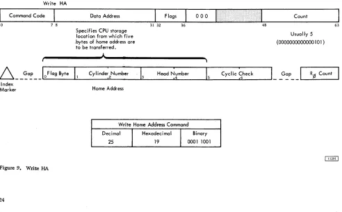
Home Address
The Home Address consists of seven bytes which define track condition and physical location within the storage device. There is one Home Address per track. Home Addresses are transferred from the CPU to the storage device only by a Write Home Address operation, and from the storage device to the CPU only by a Read Home Address operation. Writing Home Addresses is usually accomplished by utility programs.
Index Home
Merker Address
Home Address
Flag
A flag (1 byte) indicates track condition. It is nor-mally all zero bits when Home Addresses are first written. Bit significance is:
Bit FWlction
0 Zero
Zero
2 Zero
3 Zero
Flag
4 Zero Byte
5 Zero
6 Track Condition
o
indicatE:s operative track 1 indicates defective track7 Track Use
o
indicates primaty track 1 indicates alternate trackCylinder Number
The cylinder number (2 bytes) identifies the storage unit cylinder within which the data is stored.
Read/Write Head Number
The read/write head number (2 bytes) identifies a read/write head w\thin the selected cylinder.
The combination of cylinder and read/write head numbers is used to locate a specific track.
A more detailed discussion of addressing schemes will be found in the descriptions of the various storage units.
Cyclic Check
A Cyclic Check is used for error detection as de-scribed in the section on Data Checking. Two bytes are required for this check.
Gap
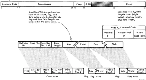
This is a fixed gap generated by the 2841 to separate the Home Address from the next recorded area. Track Descriptor Record (RO)
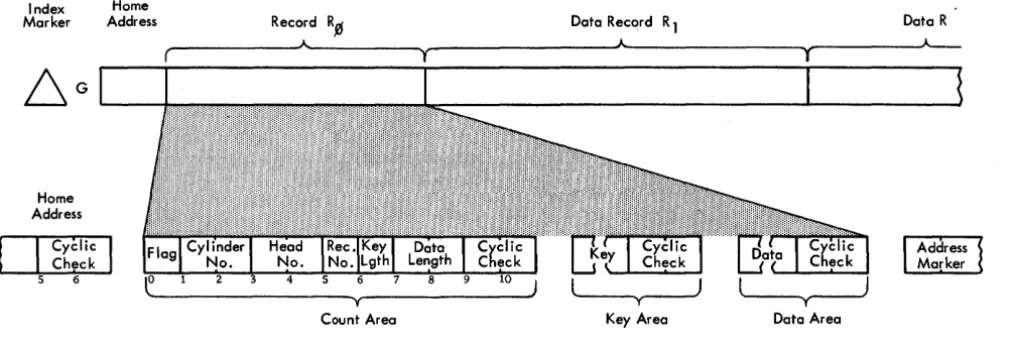
The first record following the home address on each data track is the Track Descriptor Record (Figure 1), or RO. Although it may be used to store data, RO has been designed to enable entire tracks to be moved to alternate tracks if a portion of the primary track becomes defective. For description, a pri-mary track is considered the original track on which data was stored, and an alternate track contains data which has been repositioned from a defective primary track. This repositioning is independent of the file organization scheme in use.
Count Area
This I1-byte area describes the Data Area and Key Area which follow.
Flag. Byte 0 of the Count Area is generated by the 2841 as RO is written. It is not sent from the CPU.
Bit Function or Setting
0 Zero
Zero
2 Zero
3 Zero
Flag
4 Zero Byte
5 Zero
6 Track Condition o indicates operative track 1 indicates defective track
Index Marker
Home
Address Record R~ Data Record R 1 Data R
__
---~A---~r---JA~---~---~Home Address
I
CY~liC
Check
5 6
Figure 1. Track Descriptor Record
Count Area
Bits 6 and 7 are transmitted to the flag bytes of all records on the track from the flag byte of the home address of that track.
Cylinder Number. In a primary track, bytes 1 and 2 of RO contain the cylinder number of the primary track on which this record was stored.
If this record has been moved to an alternate track, the cylinder number of the alternate track appears
in
the data area of RO of the defective primary track.Read/Write Head Number. In a primary track bytes 3 and 4 of RO contain the read/write head number of the primary track on which this record was stored. If this area has been moved to an alternate track, the head number of the alternate track appears in the data area of RO of the defective primary track.
Record Number. Byte 5 designates the sequential number of the record on the track. For RO, the record number is zero.
Key Length. Byte 6 specifies the number of bytes in the Key Area of the record (excluding check bytes).
If the record has no key, this byte is zero. This byte can indicate a Key Length from 0 to 255 bytes. Because of its intended special use with alternate track procedures, RO will normally have no Key Area.
Data Length. Bytes 7 and 8 specify the number of bytes in the Data Area of the record (excluding check
Key Area Data Area
bytes). Two bytes (16 bits) can indicate Data Length from 1 to 65,535 bytes.
Zero Data Length indicates the end of a logical file. The 2841 sends special indicators to the CPU when an End-of-File record is read or written.
Cyclic Check. Bytes 9 and 10 are used for error detection as discussed in the section on Data Check-ing.
Key Area
Although a Key Area can be written and used in RO by the commands used by the 2841, this use is purely at the discretion of the programmer. Standard use of RO by IBM Programming Systems does not include a Key Area.
A more detailed discussion of Key Area may be found in the section of this manual which describes Key Area within Data Records (R1 - Rn).
Data Area
The design and use of this area is normally pre-scribed by IBM Programming Systems. Because of this special use by the programming system, it is recommended that this area not be used for applica-tion data.
[image:8.617.27.533.59.230.2]Data Records (R
1 - Rn)
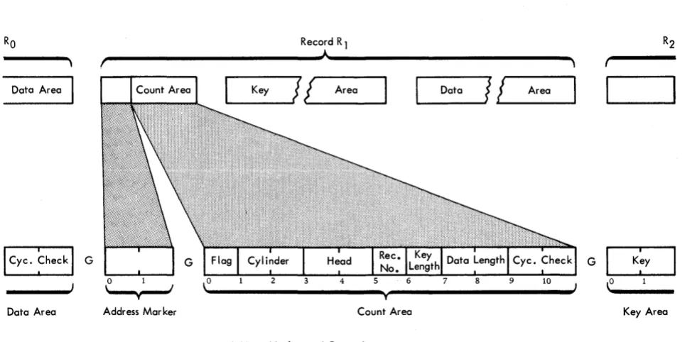
One or more data records may follow RO on a track. Count areas make each record self-formatting for maximum data organization flexibility and efficiency.
Index HA
Dcrlal
~ Address Marker
Address Marker
* May Not be Present
Record R 1 - Rn Format
D
Address Marker
This 2-byte area indicates the beginning of each record after RO (Figure 2). Address markers are supplied by the 2841 as records are written. They are used by the 2841 to locate the beginning of a record for searching, writing, and reading operations.
Record R 1
Count Area
This II-byte area describes the Key and Data Areas which follow it. Bytes 1 through 8 are created in the CPU by the program used to write the record.
Flag. Byte 0 of the Count Area is generated by the 2841 as each record is written. It is not sent from the CPU.
Flag Byte
Bit Function
o o for even-count records (RO, ~, R 4, R6) 1 for odd-count records (R
1, R3, Rs • • •• ) Used by the 2841 to ensure that all address
markers (and records) are present. The 2841 signals a missing Address Marker when two consecutive, identical bits are encountered (unless an Index Point intervenes).
Used with Record Overflow feature.
o for all non-overflow records and for the last record of an overflow chain.
for each record except the last record of an overflow.
r'---~A~---~
Data Area
Data Area Address Mar ker
[image:9.613.67.554.415.656.2]Figure 2. Address Marker and Count Area
...
_K_e_Y_~J
J
AreaT Count Area
Address Marker and Count Area
~_D_a_ta
__JI
~!
__
A_r_ea_~
G
~
2
3
4
5
Flag 6 Byte
7
Function
Zero
Zero
Zero
Zero
Track Condition 0 indicates operative track 1 indicates defective track
Track Use o indicates primary track 1 indicates alternate track
Bits 6 and 7 are transmitted to the flag bytes of all records on the track from the flag byte of the Home Address of that track by the 2841.
Cy linder Number. Bytes 1 and 2 contain the cylinder number of the track on which the data is stored.
Read/Write Head Number. Bytes 3 and 4 contain the read/write head number of the track on which the data is stored.
Record Number. Byte 5 designates the sequential number of the record on the track.
Key Length. Byte 6 specifies the number of bytes in the Key Area of the record (excluding check bytes).
If the record has no key, this byte is zero. This byte can indicate a Key Length from zero to 255 bytes.
Data Length. Bytes 7 and 8 specify the number of bytes in the Data Area of the record (excluding check bytes). Two bytes (16 bits) can indicate Data Length from 1 to 65,535 bytes. It should be noted that maximum data length is a function
of
the track capacity of the specific storage device. See the description of the Overflow Feature for records that exceed the track size.Zero Data Length indicates the end of a logical file. Special indicators are sent to the CPU when an End-of-File record is read or written.
Cyclic Check. Bytes 9 and 10 are used for error detection as discussed in the section on Check Characters.
Key Area
The Key Area concept has been provided in storage units of the 2841 family to allow searching and data accessing during a single disk, drum, or strip revolution. The Key Area can contain identifying information about a record, such as serial number, social security number, or policy number. Special commands are provided to search Key Areas for this identifying information. When the desired record is found, a read or write instruction can be issued and the Data Area read or written during the same revolution.
Comparison (during searching) is accomplished within the 2841. Thus, use of Key Areas for search-ing allows searchsearch-ing and comparsearch-ing of keys and movement of the desired Data Area to or from the CPU during a single disk, drum, or strip revolu-tion.
Key Area length ranges from 1 to 255 bytes. Two Cyclic Check bytes are added to the Key Area by the 2841. If Key Length, in the Count Area, is zero, no Key Area will be written.
Data Area
This area contains the information identified by the Count and Key Areas. Data information is organ-ized and arranged by the programmer.
Input/Output (I/O) operations involve the transfer of information to or from CPU storage. Within this concept, disk and drum storage drives and data cell drives are considered I/O devices.
The CPU program initiates I/O operations with the Start I/O instruction. Bit positions 24-31 of this instruction identify the device. Start I/O causes the channel to fetch the Channel Address Word (CAW) from main storage location 72. The command ad-dress portion of the CAW designates the location in main storage from which the channel subsequently fetches the first Channel Command Word (CCW). The CCW specifies the command to be executed and the storage area to be used.
If the channel is not busy, the channel attempts to select the device by sending the address of the device to all attached control units. The control unit specified in the address responds to its selection and awaits further instructions. The command code is sent to the selected control unit; the control unit then responds with a device status byte to the CSW.
At this time, the start
r/o
is terminated. The results of the attempt to initiate the execution of the command are indicated by the condition code in the Program Status Word, and, under certain conditions, by status bytes in the Channel Status Word.All data transfers from the channel to the 2841 are checked for parity. If a parity error is detected, a unit check signal is sent to the CSW by the 2841 and the command will not be executed.
An I/O operation may involve transfer of data to one storage area, designated by a single CCW. When data chaining is specified, data is transferred to a number of storage areas. In each case, a chain of CCWs is used, in which each CCW designates an area in main storage for a part of the operation. The program can be notified of the progress of chaining by specifying that the channel modify the Channel Status byte upon fetching a new CCW. When command chaining is specified, a series of commands is executed.
Termination of an I/O device operation normally is indicated by two CSW conditions: Channel End and Device End. The channel end condition indicates that the I/O device has received or provided all informa-tion associated with the operainforma-tion and no longer needs channel facilities. The device end signal indicates that the I/O device has terminated execution of the operation. The device end condition can occur con-currently with the channel end condition or later. If
INPUT/OUTPUT OPERATIONS
command chaining has been specified, the next CCW is fetched by the channel and the operation designated is commenced. Unusual conditions and errors ter-minate the execution of a command chain.
INSTRUCTIONS
All I/O instructions use the following format:
o 78 1516 1920 31
I/O Instruction Format
Fields in the instruction are allocated as follows:
Bit Position Field Designation
0-7 Operation (Op)
Code
8-15 Not Used
16-19
20-31
Base Address Register Location (B
1)
Displacement (D 1 )
Function
Designates the operation to be performed.
Designates the address of a general register in main storage. The register is 32 bits in length, but only the low order 24 bits are used.
The sum obtained by the addition of the content of the register at B1 and content of the D1 field identifies the channel and device addressed by the instruction. The re-sult has the format:
Bit Position Field DesilEation Function
0-7 Operation (Op) Designates the operation to Code be perfonned.
8-20 Not Used
21-23 Channel Address 000 - deSignates multiplexer channel.
001 - 110 - designates selec-tor channel 1-6. 111 - invalid combination.
24 Shared Channel 1 indicates multiplex channel Indicator or sub-channel. On a
selec-tor channel, this bit is in-cluded in the control unit address.
25-27 Control Unit 0-7 control units per channel.
28-31 Access Mechanism 0-7. Bit 28 will be 1 only if
additional access feature is installed (indicates mecha-nism 8-15).
Bit positions 24 to 31 of the I/O instruction specify a control unit and access mechanism.
?
I
C~ntrol ~nit N~.
24
t
2S 26 27Always 1 for 2841 on Multiplex Channel
28
t
29 30 31Indicates Numbers 8-15 When Add'i Access Feature Installed
Unit Address Format
A control unit number is permanently assigned to each 2841 through internal wiring at the time the unit is installed.
A maximum of 16 access mechanisms can be addressed by each control unit. A standard 2841 can control eight mechanisms; eight more can be attached with the Additional Storage feature~
Start I/O
All I/O operations are initiated by a Start I/O instruc-tion. If the channel facilities are free, Start I/O is accepted and the CPU continues its program. The channel independently selects the
I/o
device specified by the instruction.The CAW at main storage location 72 contains the protection key for the sub-channel and the address of the first CCW. The CCW so designated specifies the operation to be performed, the main-storage
area to be used, and the action to be taken when the operation is completed.
If any of the several conditions exist, Start I/O will cause the status portion, bit positions 32-47, of the CSW at main storage location 64 to be replaced by a new set of status bits. The status bits pertain to the device addressed by the instruction. The con-tents of the other fields of the CSW are not changed.
Halt I/O
Halt I/O terminates a channel operation, and the
2841 is disconnected from the channel.
Halt I/O does not cause a command byte to be transferred to the 2841. If the operation in progress was a write command, the 2841 completes the write operation by inserting valid zeros to the end of the field or track. An erase command also inserts valid zeros to complete the operation.
Test I/O
Test I/O sets the condition code in the Program Status Word to indicate the state of the addressed channel, sub-channel, and I/O device. The Channel Status Word is stored in location 64.
Test Channel
Test Channel sets the condition code in the Program Status Word to indicate the state of the channel ad-dressed by the instruction. The condition code then indicates channel available, interruption condition in channel, channel working, or channel not opera-tional. The execution of this command does not affect the 2841.
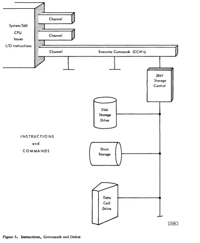
CHANNEL OPERATION
The IBM 2841 Storage Control is attached to the CPU through a set of data paths called a channel (Figure 3). So that the CPU may control a wide variety of input/output devices with a minimum of programming differences, all control units are designed to re-spond to a standard set of commands from the chan-nel. The control unit then translates these com-mands into specific operating orders for the particu-1ar input/output unit. This enables the CPU to oper-ate all input/output devices uniformly with the set of basic instructions.
Channel Status Word (CSW)
System/360
CPU
Issues
I/o Instructions
Executes Commands (CCW's)
I NSTRUCTIO NS
and
COMMANDS
Figure 3. Instructions, Commands and Orders
Data
Cell
Drive
CSW is formed, or parts of it are replaced, during I/O interruptions and during execution of I/O in-structions. The CSW is placed in main storage at location 64. It is available to the program at this location until the next I/O interruption occurs or un-til another I/O instruction generates a new CSW, whichever occurs first.
When the CSW is stored as a result of an I/O interruption, the I/O device is identified by the I/O address in the old PSW. The information placed in the CSW by an I/O instruction pertains to the device addressed by the instruction.
2841
Storage Control
The CSW has the following format:
I
KeyI
0000I
Command Address0 3 4 78
I
Device St1tus ChannelI
Count32 39 40 4748
I
31
I
63
Channel Status Word ~
[image:13.615.63.474.55.555.2]CSW Bit
Position Field Designation
0-3 Protection Key
4-7 Not Used
Function
Form the storage protection key used in the chain of operation.
Always zero.
8-31 Command Address Form an address eight positions
32 Attention
33 Status Modifier
34 Control Unit End
35 Busy
36 Channel End
37 Device End
38 Unit Check
39 Unit Exception
higher than the address of the last CCW used.
Not Used.
Set whenever a Search High, Search Equal, or a Search High or Equal command has
been executed and the con-dition satisfied.
The Status Modifier is also set whenever the 2841 is Busy. This bit, in conjunction with the Busy Bit, signifies Control Unit Busy.
Set if a Control Unit Busy status has been generated previously and the busy condition has been terminated.
Indicates that the selected device is busy. It is set when a new command chain is initiated while the selected access mechanism is still in motion due to a previous Seek command.
In conjunction with the Status Modifier bit, indicates the con-trol unit is busy. It is set when a new command chain is initi-ated while the 2841 is causing a track to be erased following a Format Write command.
See section on Two Channel Switch.
Set at the end of each channel command.
Indicates that an access mechanism is free to be used.
Set whenever an unusual or error condition is detected in the 2841 or the selected file device. A Sense 1/0 Command may then be used to identify the condition.
Indicates an End-of-File has been detected during a Read RO CKD, Read KD, Read D, Write KD, or Write D operation. It results from a Data Length of zero being detec-ted in the Count Area of a record.
CSW Bit
Position Field Designation
40-47 Channel Status
48-63 Gount
Function
When this condition is detected, no data is transferred. If Key Length is not zero, the Key Area is transferred.
Indicate channel conditions as follows:
Bit Designation
40 Program-controlled interruption 41 IncOlTect length
42 Program check
43 Protection check
44 Channel data check
45 Channel control check 46 Interface control check
47 Chaining check
Form the count of the last CCW used.
Channel Address Word (CAW)
Successful execution of start I/O causes the channel to fetch a channel address word from main storage location 72. The CAW specifies the location in main s.torage where the channel program begins.
The CAW has the following format:
Command Address
o 34 78 31
Channel Address Word
CAW fields are allocated for the following purposes:
CAW Bit
Position· Field Designation
0-3 Protection Key
4-7
Function
Forms the Storage Protection key for all commands associated with Start 1/0. This key is matched with a storage key whenever data is placed in storage.
Always Zero.
8-31 Command Address Designates the lacation of tIie first CCW in main storage.
Channel Command Word (CCW)
(CCW). The address of the leftmost position of the CCW must be divisible by four (in binary notation, the two low-order positions of the address are zero). One or more CCWs make up the channel program that directs channel operations.
The CCW specifies the command to be executed. For commands initiating I/O operations, it desig-nates the storage area associated with the operation and the action to be taken when transfer to or from the area is completed. CCWs can be located any-where in main storage and more than one can be associated with a Start I/O. The channel refers to a CCW in main storage only once. Once obtained, the pertinent information is retained in the channel.
The first CCW is fetched during the execution of Start I/O. Each additional CCW in the sequence is obtained when the operation has progressed to a point where the additional CCW is needed. Fetching of CCW s by the channel does not affect the contents of main storage.
Fields in the CCW are allocated for the following purposes:
CCW Bit
Position Field Designation
0-7 Command Code
8-31 Data Address
32
33
34
Chain Data (CD) Flag
Chain Command (cq Flag
Suppress Incorrect Length Indicator (SIU)
Function
Specify the operation to be per-formed. The 4 high-order bits specify the function to be per-formed by the addressed I/O device; the 2 low-order bits specify the channel function.
Specify the location of an 8-bit byte in main storage. This is the first location of the area designated by the CCW.
When set to one, specifies chain-ing of data. It causes the storage area designated by the next CCW to be used with the current oper-ation. The command code of the next CCW will be ignored. When bit 32 is zero, the current CCW is the last one for the operation.
When set to one, and when the CD flag is zero, specifies chain-ing of commands. It causes the operation specified by the com-mand code in the next CCW to be initiated on normal comple-tion of the current operacomple-tion.
Controls whether an incorrect length condition is to be indi-cated to the program. When this bit is set to one and the
CCW Bit
Position Field Designation
35 Skip (SKIP) Flag
36 37-39 40-47 Program-Control-Interruption (PC!) Flag Transfer-in-Channel
48-63 Count
Function
CD flag is zero in the last CCW used, the incorrect length indication is suppressed. When both the CC and the SILl flags are set to one, command chaining takes place regardless of the presence of an incorrect length indication. Absence of the SIll flag or the presence of the CD flag causes the pro-gram to be notified of the in-correct length condition when it occurs.
When set to one, specifies sup-pression of a transfer of infor-mation to storage during a read, read-backward, or sense op-eration. When bit 35 is zero, normal transfer of data takes place.
When set to one, causes the chan-nel to generate an interruption condition upon fetching the CCW. When bit 36 is zero, normal operation takes place.
Bit positions 37-39 of every CCW other than one specifying transfer in channel must contain zeros. Violation of this restriction gen-erates the program-check condi-tion. For additional information, see Control Commands
-Transfer-in-Channel.
Not used.
Specify; the llumber of 8-bit byte locations in the storage area designated by the CCW.
Program Status Word (PSW)
The PSW has the following format:
Program Status Word
ISystem Mask
I
KeyI
AMWP\o 7 8 1112 15 16
32. 3334 35 36 3940
PSW Bit
Position Field Designation
0-7 System Mask
8-11 Interrupt Key*
12 ASCII (A)*
13 Machine-Check Mask (M)*
14 Wait State (W)*
15 Problem State (P)*
16-31 Interruption Code*
32-33 Instruction Length Code (ILC)*
Interruption Code
31
Instruction Address
63
Function
Associated with I/O channels and external signals. When a mask bit is one, the source can inter-rupt the CPU. When a mask bit is zero, the corresponding source cannot interrupt the CPU and interruptions remain pending.
Identifies the cause of an I/O, program, supervisor call, or external interruption.
34-35 Condition Code (CC)*
36-39 Program Mask*
40-63 Instruction Address
*Refer to IBM System/360 Principles of Operation, Form A22-6821.
Channel Program Branching
Normally the next CCW in a chain is fetched from a core position eight bytes higher than the current CCW. This sequence can be modified in two ways:
1. If command chaining is specified in the cur-rent CCW and execution of the CCW results in a status modifier indication (without other unusual conditions detected), the channel will fetch the next CCW from a main storage location sixteen positions higher than the current CCW (one CCW is skipped). Since
all Search commands transmit.a status modifier indication, this allows branching from a command chain when the search command condition has been satisfied. 2. The programmer can also modify the CCW
chain sequence by using the Transfer-in-Channel (TIC) command. This command directs the channel to fetch the next CCW from an address specified within the TIC CCW. See Control Commands - Transfer-In -Channel for additional information.
These methods of modifying the sequence of a chain of CCWs provide branching capability in the channel program.
Control Commands
Control operations on 110 devices do not involve a transfer of data between a storage unit and the CPU. However, in certain Control operations, a few bytes or bits may be transferred between the CPU and 2841 to enable the operation to take place. These bytes are parity checked during transfer.
Erase
This command is used to erase the end of a track after a track overflow has occurred. It has the same chaining requirements as a Write Count-Key-Data command. The execution of this command causes one's to be written from the end of the Data area of the record on which the preceding search was satisfied, or the record just written by Write CKD, to the end of the track. Channel End and Device End signals are generated when Index Point is reached. Both the channel and the control unit are busy during execution of this command.
Erase Command Code
Decimal Hexadecimal Binary
17 11 0001 0001
No Operation (No-Op)
This command causes the addressed device to re-spond with Channel End and Device End. No infor-mation other than the command itself is trans-ferred to the 2841. The addressed device takes no action.
No-Operation Command Code
Decimal Hexadecimal Binary
03 03 00000011
Restore
This command is used with the 2321 only, It causes the 2321 to restore the strip from the drum to the cell. It causes Channel End to be generated upon initiation of the operation by the Control Unit and Device End when the strip is fully restored. The Restore command operates exactly like a seek com-mand except that no address is transferred to the 2841.
A Restore command is not restricted by the file protect mask. Any device other than a 2321 performs a No-op when a Restore command is given.
Restore Command Code
Decimal Hexadecimal Binary
23 17 00010111
Recalibrate
This command is used with the 2311 only. It causes the 2311 to seek to head zero and track zero. It
causes Channel End to be generated immediately and Device End to be generated when the operation is complete. Any device other than a 2311 performs a No-op when a Recalibrate command is given. A Recalibrate command works under the same File Protect Mask as a Cylinder Seek command.
Reca librate· Command Code
Decimal H exadec i ma I Binary
19 13 0001 0011
Seek
Three seek commands are associated with the 2841 Storage Control unit: Seek, Seek Cylinder, and Seek Head. After a Start I/O instruction has selected the proper channel, control unit, storage unit, and access mechanism, the Seek CCW transfers a 6-byte
Seek Address from main storage to the 2841. The CCW count (pOSitions 48-63) should specify a 6-byte count field. If the count is more than six, the 2841 operates on the first six bytes transferred and, if the CCW SILl (Suppress Incorrect Length Indicator) bit is zero, a Wrong Length Record is signalled to the CSW. If the CCW count is less than six, the CSW Unit Check bit is set, and a Sense I/O CCW may be
used to identify the Seek Check and Command Reject. The six bytes specified must form a valid address. At the completion of a successful address transfer from main storage to the 2841, a Channel End indica-tion is sent to the CSW. A Device End indicator is set in the CSW when the selected access mechanism has reached the addressed track.
A Seek command need not be preceded by any other CCW.
Seek commands operate in conjunction with the Set File Mask command.
The 6-byte seek address is arranged as follows:
Device Byte 0 Byte 1 Byte 2 Byte 3 Byte 4 Byte 5
2311 X X X 0-202 X 0-9
cylinder head
2302 X X X cylinder 0-249 X 0-45
head 0-79
X 0-9
2303 X X X cylinder head
2321 X cell 0-9 sub-cell 0-19 strip 0-9 cylinder 0-4 0-19 head
X indicates not used, but all bits must be zero.
Seek. All six seek address bytes referenced by the cCW are used to determine seek address.
Seek Cylinder. Only the four low-order bytes (bytes 2-5) referenced by the CCW are used to de-termine seek address. With the 2321, only bytes 4 and 5 are used.
Seek Head. Only the two low-order bytes (bytes 4 and 5) referenced by the CCW are used to determine seek address. With the 2321, only byte 5 is used.
Command Seek Command Code
Decimal Hexadecimal Binary
Seek 07 07 00000111
Seek Cylinder 11 OB 00001011
Seek Head 27 1B 00011011
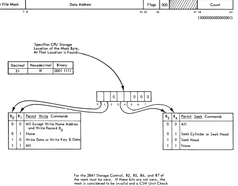
Set File Mask (Figure 4)
Set File Mask
BO
0
0 0
7 8
Data Address
Specifies CPU Storage Location of the Mask Byte, At That Location is Found:
Permit Write Commands
All Except Write Home Address and Write Record RO
None
Write Data or Write Key & Data All
31 32
Count
36 47 48 63
( 0000000000000001)
B3 B4 Permit Seek Commands
·0 0 All
0 Seek Cylinder or Seek Head
0 Seek Head None
For the 2841 Storage Control, B2, B5, B6, and B7 of the mask must be zero. If these bits are not zero, the mask is considered to be invalid and a CSW Unit Check signal is generated. A subsequent Sense I/O command will indicate Command Reject.
Figure 4. Set File Ma;k
Device End signal are sent to the CSW. The byte of data that is sent to the 2841 describes the Write and Seek functions that can be performed in the CCW chain. Set File Mask can be issued anyplace within a CCW chain. At the completion of the CCW chain, the File Mask is reset to all zeros.
If a Seek or Write command is issued which violates the File Mask, the command is not execu-ted, and a Unit Check signal is generated in the CSVil Status Byte. A subsequent Sense I/O command sig-nals File Protect and Command Reject if the gener-ation was a write. For a seek opergener-ation, File Pro-tect is set; for a write operation, both File ProPro-tect and Command Reject are set.
A Set File Mask command can be issued only once within any given CCW chain. If an attempt is made to issue more than one Set File Mask command with a given CCW chain, a Unit Check signal is generated in the CSW Status Byte. A
subsequent Sense I/O command indicates Command Reject and Invalid Sequence.
Space Record
This command enables the 2841 to pass over the next record on a track. It allows the 2841 to retrieve subsequent records from a track when the Count Area of a preceding record is not readable.
The execution of the Space Record command causes the 2841 to search for the next Address Marker on the track. Upon detection of the Address Marker, Channel End and Device End signals are
genera~ed. Thus, the following CCW searches for the Address Marker following the one detected by the Space Record command.
[image:18.612.44.517.60.431.2]End signals are generated immediately. The effect of this sequence is to cause Record RO to be passed over.
The Space Record command does not detect a Missing Address Marker. However, if an Address Marker is missing, it is detected on all valid com-mands chained from the Space Record command except Search ID commands.
The Space Record command must be chained from either a Search or a Read command.
Space Record Command Code
Decimal Hexadecimal Binary
15 OF 00001111
Transfer In Channel (TIC)
The Transfer in Channel command provides chaining between CCWs not located in adjacent CPU storage locations. The next CCW is fetched from the loca-tion specified by the Data Address field of the TIC CCW.
TIC does not initiate any channel I/O operation and the I/O device is not signalled that this command is being executed.
TIC may not be the first CCW designated by a CAW. One TIC command may not transfer directly to a second TIC command.
When either of these errors is detected or when an invalid address is specified in Transfer in Chan-nel, the program-check condition is generated. De-tection of these errors during data chaining causes the operation of the I/O device to be terminated, whereas during command chaining they cause an interruption condition to be generated.
Bit positions 0-3 and 32-63 are ignored. Bits 29-31 must be zero to meet the boundary require-ments for double words.
TIC Command Code
Decimal Hexadecimal Binary
X8 X8 XXXXIOOO
Positions Marked "X" Are Ignored
Sense I/O Commands
Four bytes of sense condition information are pro-vided by the 2841 to identify the setting of the Unit Check bit in the CSW Status Byte. These Sense Bytes
are transferred to the Channel by a Sense I/O com-mand.
The Data Address portion of the CCW directs the bytes to a specific CPU storage location.
Sense
I/o
Command CodeDecimal H exadec i ma I Binary
04 04 0000 0100
The significance of a "1" condition for each bit is:
Byte Bit Designation
o o
o
0 2
0 3
0 4
0 5
Command Reject
Intervention Required
Bus Out Parity Check
Equipment Check
Data Check
Overrun
Significance of "1"
Indicates that the 2841 has received an invalid operation code, an in-valid sequence of commands, an invalid Seek Address*, or a file mask is violated on a write com-mand. (See Set File Mask. )
Indicates that the specified file is not physically attached to the system or, if physically attached to the system, it is not available for use because the file motor is not on, a cover interlock is open, etc.
Indicates that the 2841 has detected a parity error during the transfer of a command or data from the chan-nel to the 2841. A parity error detected during command transfer signals a Parity Check, not a Com ... mand Rej ect.
Indicates that an unusual condition is detected in the control or storage unit. Conditions covered by this bit are defined by Sense Byte 2.
Indicates that a data error has been detected in the information re-ceived by the 2841 from the storage unit.
Indicates that a chained CCW was issued but that it was received too late to be properly executed; or that a byte was received during Reading or Writing; or that a byte was received too late (during a read or write operation) to be executed properly.
Byte Bit Designation Significance of 11111
o 6
o 7
o 2 3 4 Track Condition Check Seek Check Count Area Check
When Writing, the remaining por-tion of the record area will be filled with valid zeros and the Overrun check will be generated. When Reading, the remaining portion of the record will continue to be read into the 2841 and the Overrun Check will be generated.
Indicates defective track.
Indicates that the file has been un-able to complete a Seek because:
1. Transferred Seek address is out-side the v.!lid address boundaries of the storage device. Unused seek address bytes must be a valid address for the device selected. Command Rej ect is also set. 2. Less than six seek address bytes
were sent. Equipment failed which resulted in the access mech-anism going to either the inner or outer stop. In this case Command Rej ect is not set.
Indicates that a data error has been detected in a Count Area read from the storage device. Data Check (bit 4) in Byte 0 is also tumed on. Error detection is the same as described for Data Check.
Track Overrun Indicates that writing has not been completed by the time the Index Point is detected. This type of error is created during a Write RO or Write Count, Key, and Data operation.
Cylinder End
Invalid Sequence
No Record Found
Indicates that the CCW Command Chain has not been completed, and Cylinder End has been detected.
Indicates that an attempt has been made to execute an invalid sequence of CCWs or that two Set File Mask commands appear in the same command chain. Valid command sequences are
de-fined in the individual command descriptions. Command Rej ect (Byte 0 bit 0) is also set when an invalid sequence is detected.
Indicates that while executing a chain of CCWs, the 2841 has detected two Index Points without completing an intervening command to read or
Byte Bit Designation Significance of 11111
write the Data Area, Read Home Address, or Read RO. It is also set in conjunction with Missing Address Marker if there is no data on the track. No Record Found is never set if the Multi-Track bit in the command (Bit 0) is on.
5 File Protected Indicates that a Seek or Write CCW
6
7
was issued contrary to the file mask. The Command Reject bit is also set by this condition, if the operation is a write operation.
Missing Ad- A missing Address Marker, which dress Marker may indicate a missing record is
detected during the execution of command or chain of commands which operates on successive Count Areas on a track. The con-dition detected is two successive records on a track with equal bit conditions in bit 0 of the Flag bytes, with no intervening Index Point.
Overflow Incomplete
A missing Address Marker is also detected if two Index Points are passed with no intervening Address Marker record on the track.
When a Missing Address Marker is detected, this bitand bit 4 of Sense Byte zero (Data Check) will be tumed on for all commands or chained commands except Search ID CCWs. The Search ID CCW may be used to pass over the Mis-sing Address Marker so that the re-maining data on the track can be retrieved. Missing Address Marker is set in conjunction with No Record Found if there is no data on the track.
This bit is used with the Record Overflow special feature. It is set with other indicators to signal conditions as follows:
Condition
Sets Overflow Incomple.te and Other Indicator:
Overflow to a Track Condition defective track (Byte 0, bit 6)
Overflow from an alternate track
Byte Bit Designation Significance of "1 II
7 Overflow Overflow to File Protected
Incomplete File Protected (Byte 1, bit 5)
boundary Command Rej ect
(Byte 0, bit 0)
Overflow to Set for write only.
wrong track Seek Check
(Head number (Byte 0, bit 7). unequal)
A Track Condition check is generated under the following conditions:
1. If an overflow record is being read, written, or searched which overflows to a defective track. The interrupt occurs after the last byte on the previous track has been oper-ated on and before the first byte for the de-fective track is requested from or sent to the channel. In this case Overflow Complete is also set. Command Reject is also set if
the operation was a write.
2. A Search HA, Read HA, or Read RO causes a head switch to a defective track during a multiple track operation, when a Search operation other than Search HA is attempted. The interruption occurs prior to transfer of any data to or from the channel.
Write commands never set track con-dition checks.
Sense Bytes 2 and 3. These bytes are provided to assist the Customer Engineer when using diagnostic programs to locate equipment malfunctions.
Device Reserve (Two-Channel Switch Special Feature)
Without the Two-Channel Switch feature installed, Device Reserve is rejected by the 2841 and the Unit Check bit in the CSW Status Byte is set. The Com-mand Reject bit in Sense Byte 0 is set to indicate what caused the Unit Check condition.
With the Two-Channel Switch feature, a Device Reserve command causes the addressed device to be reserved to the channel issuing the command.
The device then remains reserved to the same channel until that channel executes a Device Release command addressed to the specific device, or until the CPU is .reset.
A Device Reserve command is rejected with a Busy indication in the CSW if any normal Busy con-dition exists. However, a Device Reserve command is executed regardless of any abnormal file status condition, such as off-line, unsafe, etc.
A Device Reserve command is rejected when a Set File Mask command precedes it in the same command chain. The Unit Check bit in the CSW is set when the command is rejected, and the Command Reject and Invalid Sequence bits are set to indicate the conditions which caused the Unit Check.
The Device Reserve command performs all of the functions of a Sense I/O command in addition to the functions described in this section.
Device Reserve Command Code
l>ecimal Hexadecimal Binary
180 54 1011 0100
Device Release (Two-Channel Switch Special Feature)
Without the Two-Channel Switch feature installed, Device Release is rejected by the 2841 and the Unit Check bit in the CSW Status Byte is set. The Com-mand Reject bit in Sense Byte 0 is set to indicate what caused the Unit Check condition.
With the Two-Channel Switch feature, a Device Release command terminates the reservation of the addressed device to the channel. This command is rej ected with a Busy indication in the CSW if any normal busy conditions exists. However, a Device Release command is executed regardless of any ab-normal file status condition such as off-line, unsafe, etc.
A device is normally reserved to a particular channel whenever that channel exectues a Device Re-serve command. The device remains reRe-served to the same channel until that channel causes the 2841 to execute a Device Release command, or until the CPU is reset.
A Device Release command is rejected when a Set File Mask command precedes it in the same com-mand chain. The Unit Check bit in the CSW is set when the command is rejected, and the Command Reject and Invalid Sequence bits in the Sense Bytes are set to indicate the conditions which caused the Unit Check.
A Device Release command performs all of the functions of a Sense I/O command in addition to the functions described in this section.
See Two-Channel Switch for additional informa-tion.
Device Release Command Code
Decimal Hexadecimal Binary
Search Commands
On all Search operations, the Channel operates in the Write mode while the storage unit operates in the Read mode. The 2841 compares the information coming from CPU storage and the information com-ing from the storage unit.
If the search condition is satisfied, a status modifier indication is sent to the CSW and the chan-nel fetches the next CCW in the command chain from a position sixteen positions higher than the current (Search) CCW. This allows modification of a com-mand chain as a function of the data recorded on the direct access device.
On all Search commands, Command Code bit 0 determines whether this is to be a multiple track operation; that is, whether switching to the next read/write head in the cylinder is to occur when the Index Point is detected. If bit O. is not set (0), head switching does not take place; if bit 0 is set (1), head switching does take place. If head switching has occurred, the next track will be used if the Search Command is repeated. This allows for se-quential searching of an entire cylinder by repeating the Search Command once for each record to be searched.
The following command chain illustrates the procedure for reading a record identified by a key stored at location a in the CPU.
Command Chain
Search Key a
TIC *-8 Read Data
f3
Function
Compare Key with Search Argument
Transfer Back to Search Read Data Area if Status Modifier was Returned from Search
The channel is busy during a search operation.
Search Home Address Equal (Search HA)
This command causes the 2841 to search for the Index Point, then compare four bytes of Home Ad-dress data (CCHH) coming from main storage with four bytes of Home Address data coming from the storage device. The Flag byte is not transferred or compared during this command.
If a logical comparison is equal, a Channel End, Device End, and Status Modifier signal is generated in the CSW status byte. If the logical comparison is lUlequal, then a Channel End and Device End are generated.
Search Home Address does not generate a No Record Found signal if .the specified Home Address is not found.
If the CCW Count is greater than four bytes, the Search operation is completed when the 2841 count equals zero. The 2841 terminates the command with a Channel End and Device End. The Status Modifier is generated if the logical comparison was satisfied.
If the CCW Count is less than four bytes, the logical comparison between the data coming from CPU Storage and the data coming from the storage unit continues until the CCW Count reaches zero. At the time the 2841 count reaches zero, a Channel End and Device End are generated. A Status Modifier is generated if the search condition was satisfied on the short field.
If a Parity Check, Overrun, or Data Check is detected, Unit Check, Channel End, and Device End signals are generated in the CSW at the completion of the command.
A Search Home Address command does not have to be preceded by any other CCW in order to be exe-cuted.
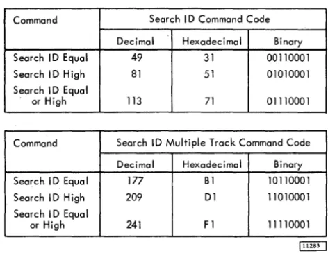
Search Identifier (Search ID)
Search ID commands (Figure 5) cause a comparison to be made between five bytes of data from CPU storage and the five byte record identifier portion of a count area from the storage unit.
Record Identifier
---~~---
....
---~---
Count Area ~The ID to be searched is the ID of the record following the next Address Marker or Index point, in which case ij.0 is searched.
If the CCW count is greater than five bytes, the Search operation is completed when the 2841 count equals zero. The 2841 terminates the command with a Channel End and Device End. The Status Modifier is generated if the logical comparison was satisfied.
If the CCW count is less than five bytes, the logical comparison between the data coming from core storage and the data coming from the file con-tinues until the CCW COlUlt reaches zero. When the 2841 count reaches zero, a Channel End and Device End are generated. A Status Modifier is generated
Command Search I D Command Code
Decimal Hexadecimal Binary
Search ID Equal 49 31 00110001
Search I D High 81 51 01010001
Search I D Equal
or High 113 71 01110001
Command Search ID Multiple Track Command Code
Decimal Hexadecimal Binary Search I D Equa I 177 B1 10110001
Search ID High 209 D1 11010001
Search I D Equal
or High 241 F 1 11110001
Figure 5. Search Command Codes
If a Parity Check, Overrun, or Data Check is detected during a Search-ID operation, Unit Check, Channel End, and Device End signals are generated at the completion of the command.
A Search ID command does not have to be pre-ceded by any other CCW in order to be executed.
If Command Code bit
°
(multiple track) is 0, the search is confined to one track and can be re-peated until either the Search Condition is satisfied or until two Index Points are sensed; at which time Unit Check (No Record Found), Channel End, and Device End signals are generated.If the multiple track bit is a 1, the search can be repeated until the Search Condition is
satis-fi~d or until the End-of-Cylinder is detected. At this time a Unit Check (End-of-Cylinder) signal is generated.
Search ID Equal. If a logical comparison on equal is encountered, Channel End, Device End, and Status Modifier signals are generated.
[image:23.618.62.298.54.236.2]Searcl;t. ID High. This command operates in a manner similar to that of the Search ID Equal command, ex-cept that the comparison is made for a high condition. The high condition indicates that the ID on the Storage Unit is higher than the ID in main storage. The com-parison is made byte by byte.
Search ID Equal or High. This command operates in
a manner similar to that of the Search ID Equal com-mand except that the comparison is made for either an equal or high condition. The equal or high con-dition indicates that the ID on the storage device is equal to or higher than the ID in main storage.
Search Key
Execution of a Search Key command causes a com-parison to be made between bytes of data from main storage and a Key from the storage device. The Key to be searched is the Key of the record following the next Address Marker. Search Key will pass over RO unless chained from a Search ID that has searched the ID of RO.
If the CCW countis greater than the Key length, the Search operation is completed when the 2841 count equals zero. The 2841 terminates the com-mand with a Channel End and Device End. The Status Modifier is generated if the logical comparison was satisfied.
If the CCW count is less than the Key length, the logical comparison between data from CPU stor-age and the data from the storstor-age unit continues un-til the CCW count reaches zero. When the 2841 count reaches zero, a Channel End and Device End are gen-erated. A Status Modifier is generated if the Search Condition was satisfied on the (short) field.
If a Parity Check, Overrun, or Data Check is detected during the Search -Key operation, Unit Check, Channel End, and Device End signals are generated at the completion of the command.
A Search -Key command does not have to be pre-ceded by any other CCW in order to be executed.
If the multiple track bit is 0, the search can be confined to one track and can be repeated until either the search condition is satisfied or until two Index Points are sensed; at which time a Unit Check (No Record Found), Channel End, and Device End signals are generated. If the multiple track bit is
1, the search can be repeated until either the
search condition is satisfied or until End-of-Cylinder is detected. If of-Cylinder is detected, an End-of-Cylinder indication is generated.
The Search Key command never returns a Status Modifier if the Key Length of the search record is zero.
Search Key Equal. If a logical comparison on equal is encountered, Channel End, Device End, and Status Modifier signals are generated. If the logical comparison is unequal or the Record has no Key area, then Channel End and Device End signals are generated.
Search Key High. This command operates in a man-ner similar to that of the Search-Key Equal com-mand except that the comparison is made for a high condition. The high condition indicates that the key in the storage unit is higher than the key in CPU storage.
Search Key Equal or High. This command operates in a manner similar to that of the Search Key Equal command except that the comparison is made for either an equal or high condition. The equal or high condition indicates that the key in the storage unit is equal or higher than the key in CPU storage.
Command Search Key Command Codes
Decimal Hexadecimal Binary
Search Key Equal 41 29 00101001
Search Key High 73 49 01001001
Search Key Equal
or High 105 69 01101001
Command Search Key Command Codes, Multiple Track
Decimal Hexadecimal Binary
Search Key Equal 169 A9 10101001
Search Key High 201 C9 11001001
Search Key Equal
or High 233 E9 11101001
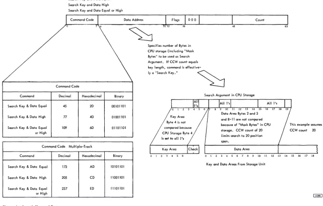
Search Key and Data (File Scan Special Feature)
The File Scan feature provides an automatic rapid search for a specific set of conditions. The search is carried out over both Key and Data areas of a record. Prior to executing a File Scan operation, a "control mask" is set up in main storage. The mask consists of bytes of information on which a comparison is or is not to be made. The bytes on which a comparison is not to be made are filled with l's prior to the search.
If the multiple track bit is off (0), the search can be confined to one track until the condition is satisfied or until two Index Points are sensed, at which time Unit Check (No Record Found), Channel End, and Device End signals are generated. If the multiple-track bit is 1, the search can be repeated until the specified condition is met or until Cylinder is encountered, at which time an End-of-Cylinder signal is generated.
No more positions than the number specified by the CCW Count are compared. If the CCW Count is greater than Key Length plus Data Length