Duobinary Modulation Format in Optical
Communication Systems
Pavol Šalík
*, Filip Čertík, Rastislav Róka
Institute of Telecommunications, Slovak University of Technology, Slovakia
Copyright © 2015 Horizon Research Publishing All rights reserved.
Abstract
This paper presents the environment of the optical fiber and digital information transmission over optical fiber, using signal transformation technique called duobinary modulation technique. We propose a complete duobinary encoder and duobinary decoder that we tested in Matlab simulink R2014B. In the final part, it will be shown a comparison of duobinary modulation technique with on-off keying modulation techniqueKeywords
Duobinary Modulation, Modulation Techniques, The Optical Path, Parameters of the Optical Fiber, Simulation Program1. Introduction
Nowadays, an interest in the signal transmission through optical fibers rapidly increases due to the transmission bandwidth. To increase the performance of the optical transmission system the analysis of optical fiber is required. The different modulation and coding techniques can be used respect to optical fiber effects to achieve optimal performance for transmission system.
Each optical fiber represents a transmission system, which is frequency dependent. A pulse propagation inside this transmission system can be described by the nonlinear Schrödinger equation (NLSE), which is derived from Maxwell equations. From the NLSE equation we can expresses effects in optical fibers that can be classified as:
a) linear effects, which are wavelength depended, b) nonlinear effects, which are intensity (power)
depended. a) Linear effects
Major impairments of optical signals transmitted via optical fiber are mainly caused by linear effects - the dispersion and the attenuation. The attenuation limits power of optical signals and represents transmission losses. Nowadays, optical transmission systems are able to minimize impact of the attenuation by deploying regenerators or all optical amplifiers like Raman or EDFA amplifiers. Another source of linear effects represents the
dispersion that causes broadening of optical pulses in time and phase shifting of signals at the fiber end. There are three dispersion types:
modal dispersion caused by the different propagation velocity of signal modes in multimode fibers.
chromatic dispersion caused by the different propagation velocity of signal wavelengths from a laser source via optical fibers.
polarization mode dispersion caused by the birefringence effect of nonsymmetrical and imperfect optical fibers.
More detailed analysis of linear effects are published in [1], [2].
b) Nonlinear effects
These effects play an important role in the long haul optical signal transmission. We can classify nonlinear effects by following way:
Kerr nonlinearities are self-induced effects, where the phase velocity of the pulse depending on the pulse’s own intensity. The Kerr effect describes a change in the fiber refractive index due to electrical perturbations. Due to the Kerr effect, we are able to describe following effects :
Self-phase Modulation (SPM) - effect that changes the refractive index of the transmission medium caused by intensity of the pulse.
Four Wave Mixing (FWM) - effect that by mixing of optical signals a fourth wave can be arisen and can appear in the same wavelength as one of the mixed wave.
Cross-phase effect (XPM) - effect where optical pulse can change the phase of another pulse with different wavelength. This effect causes a spectral broadening. Scattering nonlinearities occur due to a photon inelastic
scattering to lower energy photons. The pulse energy is transferred to another wave with a different wavelength. Two effects appear in the optical fiber:
Stimulated Brillouin Scattering (SBS) and Stimulated Raman Scattering (SRS) - effects that change variance of light wave into different waves when the intensity reaches certain threshold.
[3], 4], [5].
The duobinary modulation technique is a combination of amplitude and phase modulations that can resist to various optical fiber effects especially dispersion The duobinary encoding is a scheme of correlative coding in partial response signaling. The modulated signal can be produced by adding 1 bit delayed data to the present data bit to give three levels information. An identical effect can be achieved by applying a low-pass filter to the ideal binary data signal. The duobinary modulation is achieved by 100% overdriving a Mach-Zehnder modulator with the duobinary encoded electrical signal. The three level signal can be demodulated into a binary signal using an optical detection receiver. The advantage of this coding is that the duobinary signal has narrower bandwidth compared to the binary modulated signal and the effect of fiber dispersion is reduced.
2. Duobinary Modulation
The duobinary modulation is a scheme for transmitting R bits/sec signal data rates using less than R/2 Hz bandwidth. Due to the Nyguist theorem, the minimum bandwidth required to transmit R bits/sec is R/2 Hz to neglected the intersymbol interference (ISI). This result means that duobinary pulses will be affected with ISI, but in the controlled limits, that we can reconstruct the original values. Duobinary can be described as combination of ASK and PSK modulation techniques[6], [7], [8].
When the intersymbol interference ISI occurs substitution phase units between zero causes, overlapping edges contributions are deducted. This is an advantage over on-off keying where in the unit having the same phase zero with the result that the overlapping edges are added together[7], [8], [9].
Transmitted signal
𝑥𝑥(𝑡𝑡) =∑∞𝑘𝑘=−∞𝑑𝑑𝑘𝑘𝑞𝑞(𝑡𝑡 − 𝑘𝑘𝑘𝑘),𝑑𝑑𝑘𝑘= 0,1 (1)
Where dk – data bits
q(t) – transmitted puls T=1/R – bit period
The duobinary scheme transmit pulses affected with ISI
as follows
𝑞𝑞(𝑘𝑘𝑘𝑘) =�1 𝑘𝑘0 𝑜𝑜𝑡𝑡ℎ𝑒𝑒𝑒𝑒𝑒𝑒𝑒𝑒𝑒𝑒𝑒𝑒= 0,1 (2) We see from this formula, a receiver does not recover the data bit dk , but (dk-1+dk). The receiver does the XOR operation of adjacent bits instead of recovering single data bits. The influence of the ISI cause transmitted pulse overlapping in the time domain and narrowing the pulse spectrum. The pulse resistant to distorting effects increases with narrower spectrum[8], [9].
The transmitted signal
𝑥𝑥(𝑡𝑡) =∑∞𝑘𝑘=−∞𝑐𝑐𝑘𝑘𝑞𝑞(𝑡𝑡 − 𝑘𝑘𝑘𝑘) (3)
2.1. Duobinary Modulator
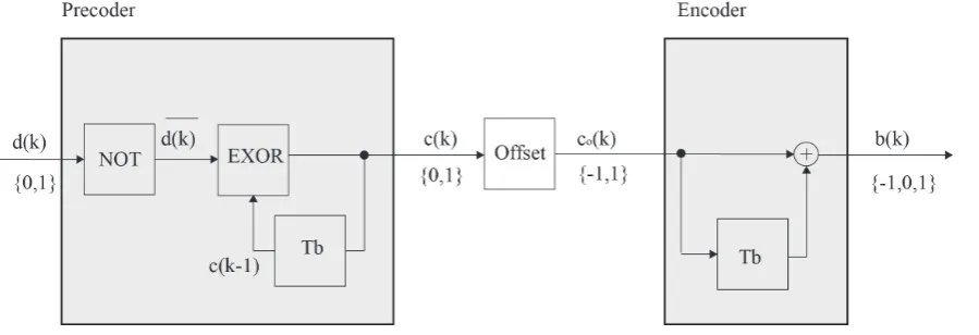
The complete duobinary transmitter scheme is shown in figure 1. The inventor output is sent to the differential precoder input that defends cyclic decoding error in the receiver. The signal is sent out to the differential encoder, where is mapped on values -1 0 1. The level -1 represents bit with amplitude 1 and phase - 90°[7], [10], [11].
Table 1. Binary to duobinary transformation
k 1 0 1 2 3 4 5 6 7 8 9
d(k) 0 0 0 0 1 0 1 1 0 1
𝑑𝑑(𝑘𝑘) 1 1 1 1 0 1 0 0 1 0
c(k) 0 1 0 1 0 0 1 1 1 0 0
c0(k) -1 1 -1 1 -1 -1 1 1 1 -1 -1
b(k) 0 0 0 0 -1 0 1 1 0 1
The table 1 shows duobinary transformation process, where k is the i-th bit, d(k) represents binary signal generated by Bernoulli generator, d(k) is negotiation of d(k) bits, c(k) represents signal after differential precoder which is XOR operation of d(k) with previous c(k) bit, c0(k) is c(k) bits
[image:2.595.86.536.573.727.2]where logical zerous are changed to -1 and the b(k) represents duobinary signal which is sum of two adjacent bits of c0(k).
2.2. Duobinary Demodulator
[image:3.595.57.290.236.332.2]The receiver decodes a received duobinary signal back to the binary data. The complete duobinary receiver scheme is shown in figure 2. Decode rule is described in table 2, where E(k) detects the magnitude of the received signal and is given result of 0 for the 0 and -1 (-1 is 1 with phase -π) and level 1 for the 1 level magnitude of the duobinary signal. F(k) detects the signal phase and is giving result of 1 for the 0 and 1 magnitude levels of duobinary signal and 0 for the 1 with phase -π. These flag bits are attached with the exclusive OR gate and then we will get d(k), which needs to be negated to acquisition original binary data signal d(k)[7], [11], [12].
Figure 2. Transformation duobinary to binary data Table 2. Duobinary to binary transformation
k -1 0 1 2 3 4 5 6 7 8 9
b(k) 0 0 0 0 -1 0 1 1 0 1
E(k) 0 0 0 0 0 0 1 1 0 1
F(k) 1 1 1 1 0 1 1 1 1 0
d(k) 1 1 1 1 0 1 0 0 1 0
d(k) 0 0 0 0 1 0 1 1 0 1
3. Transmission Experiments
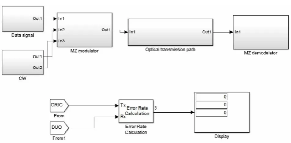
The presented simulation model comes out from the simulation model for optical communications introduced in [13]. A modeling is performed in Matlab Simulink 2014. The paper uses simulation model to demonstrate resistant of the duobinary modulation technique to optical transmission effects. The complete duobinary transmission system is shown in figure 3.
The Mach-Zehnder modulator (MZ) with continous wave (CW) is used to transmit duobinary signal. Block CW includes block of creating constructive and high frequency wave, which is used as carrier wave. MZ demodulator represents duobinary coherent receiver that detect signal amplitude and phase. Optical transmission path block represents optical transmission path with parameters: the fiber length – 80 km, the optical wavelength – 1550 nm, the attenuation coefficient – 0,21 dB/km, the input power – 1 mW. More specific descriptions of created block effects are introduced in [1], [2], [3].
The figure 4 shows different transmission signals in the optical transmission system, where a) is a bit sequence generated by Bernoulli generator b) represents a bit sequence waveform after inverter c) represents a signal after differential precoder, d) is a final encoded duobinary signal. e) is a waveform after Gaussian filter that emulates real generated signal.
The figure 5 represents output of the Mach-Zehnder modulator. From the figure above, the phase shift occurs due to the combination of 1-0-1 and negated ISI.
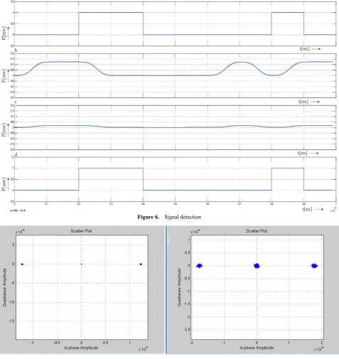
[image:3.595.68.544.493.728.2]Signal detection is based on theory described in this paper. The figure 6 shows principle of duobinary decoding, where signal a) is transmitted data signal b) represents output of the Mach-Zender modulator, c) is received duobinary signal, d) represents reconstructed binary data. We can see, data are received correctly, because signal a) is same as d)
Figure 4. Different transmission signals in the optical transmission system
[image:4.595.63.547.82.593.2]Figure 6. Signal detection
a) b)
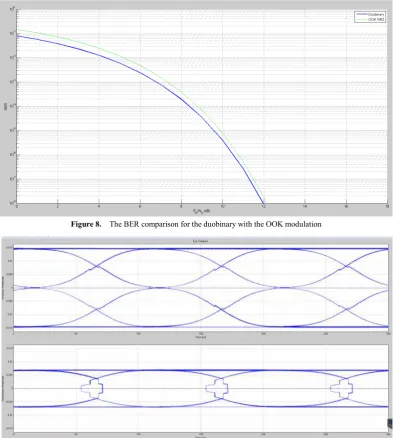
Figure 8. The BER comparison for the duobinary with the OOK modulation
Figure 9. The Eye diagram for the duobinary modulation
4. Simulation Results
The simulation is made at 80 km optical fiber with chromatic and polarization mode dispersion (10 ps/nm.km) and attenuation 16,8 dB. Laser is adjusted to 1550 nm with 1 mW power. The transmission data speed is 10 Gbit/s.
The figure 7 shows distribution of condition in magnitude frequency layer. Bits have three conditions. “1”,”0” “-1” where -1 is bit with amplitude 1 and phase -π. The transmitted signal is attenuated and the dispersion of bits are due to channel noise and dispersion. The figure 8 shows the Bit Error Rate (BER) comparison of duobinary modulation with OOK and figure 9 shows the eye diagram for duobinary modulation. The duobinary modulation shows the better BER performance than OOK modulation, as we can see from figure 8, where the duobinary needs less Eb/N0 for the same
BER. The difference between BER is not that significant, but duobinary has narrower spectrum represent better resistant to some optical effects.
5. Conclusions
We demonstrated the simulation of duobinary modulation at the 10 Gb/s. The experimental results show that the duobinary modulation is more resilient to dispersion than OOK NRZ modulation scheme. The BER curves show that duboinary have better resistant to optical fiber effects. The main advantage of the duobinary modulation is that it used for transmitting only one bit half bandwidth than OOK. Therefore, this modulation is more resilient to dispersion and applicable to the distance optical systems, which will be discussed in next article.
Acknowledgements
Institute of Telecommunications, within the scope of the projects KEGA No. 039STU-4/2013 “Utilization of Web-based Training and Learning Systems at the Development of New Educational Programs in the Area of Optical Transmission Media”.
REFERENCES
R. Róka, F. Čertík, "Modeling of Environmental Influences at [1]
the signal transmission in the optical transmission medium,"International Journal of Communication Networks and Information Security, vol. 4, No. 3. S146- 162. ISSN 2073-607X.
R. Róka, F. Čertík,"The Nonlinear FWM Effect and its [2]
Influence on Optical Signals Utilized Different Modulation Techniques in the WDM Transmission Systems,"OK 2012 – 24th Conference, Praha (Czech), ISBN 978-80-86742-36-6, 25.-26. 10. 2012
F. Čertík, R. Róka,"Nonlinear SPM and XPM Effects and [3]
their Influence on Optical Signals Utilized Different Modulation Techniques in WDM Transmission Systems,"
OK 2014 – 26th Conference, Praha (Czech), 23.-24. 10. 2014 E. Iannone, F. Matera, A. Mecozzi, M. Settembre, "Nonlinear [4]
Optical Communication Networks,"Johnwiley and sons, pp. 20-50, TK5103.59.N66, 1998
K.-P. Ho, "Phase-Modulated Optical Communication [5]
Systems,"2005 Springer Science+Business Media, Inc, pp. 111 - 180, ISBN 0-387-24392-5, ISBN 978-0387-24392-4
P. Šalík, "Digital Modulation Formats in optical transmission [6]
medium".ELOSYS 2014 - 20th conference, Trenčín (Slovak), pp. 43--47. ISSN 1335-2547.
R. R. Mahmud, M.A.G. Khan, S.M.A. Razzak.-"Design of a [7]
Duobinary Encoder and DecoderCircuits for Communication Systems". 6th International Conference on Electrical and Computer Engineering ICECE 2010, 18-20 December 2010. Shankhar H. "Duobinray modulation for optical systems [8]
Lightwave".Jun2006 IEEE Journal of Lightwave, Vol. 23 Issue 6, pp4-11
W. Kaiser, T. Wuth, M. Wichers and W. [9]
Rosenkranz, ”Reduced Complexity Optical Duobinary 10Gb/s Transmitter Setup Resulting in an Increased Transmission Distance” IEEE photonics technology letters august 2001
W. Kaiser, M. Wichers, T. Wuth, W. Rosenkranz, C. Scheerer, [10]
C. Glingener, A. Färbert, J.-P. Elbers and G. Fischer: 'SPM-limit of duobinary transmission'. Proc. ECOC 2000, Munich, Sep. 3-7.
A. Rahman, M. Broman et al, “Optimum Low Pass Filter [11]
Bandwidth For Generating Duobinary Signal For 40 Gb/S Systems,” Thin Film Technology Corp.1980
C. Xie et al, “Improvement of Optical NRZ and RZ [12]
Duobinary Transmission Systems with Narrow Bandwidth Optical Filters,” IEEE Photon. Technol. Lett., vol. 16, no. 9, pp. 2162-2164, Sep. 2004.
R. Róka, Fixed Transmission Media. In: Technology and
[13]