Journal of Chemical and Pharmaceutical Research, 2013, 5(12):59-63
Research Article
CODEN(USA) : JCPRC5
ISSN : 0975-7384
Study on double position molding technology of labyrinth type drip
irrigation tape
Yuefeng Yuan
1*, Xiangyang Zhang
1, Xiaodong Zhao
1, Yuenian He
2, Yigang Yu
2, Chunbo
Qian
2and Zhoujie Huang
21
School of Naval Architecture and Ocean Engineering, Zhejiang Ocean University, Zhoushan, Zhejiang, China 2
Zhoushan Ange Machinery Co. Ltd, Zhoushan, Zhejiang, China
_____________________________________________________________________________________________
ABSTRACT
The drip irrigation technology can greatly save freshwater resources, effectively improve the output of agricultural products, shorten time to market, and reduce the costs of fertilizer, pesticide and labor, so it has a broad prospect of application. The double position molding technology of labyrinth type drip irrigation tape, which four tapes out of one molding equipment (four per one), is presented in this paper. And the double station molding device is designed. The experimental results show that the molding device has stable size and high quality. Compared with the traditional single position molding device, it has higher molding efficiency, lower cost of production, and needs lesser labor.
Keywords: Drip irrigation, Double position, Molding wheel, Screw, Labyrinth
_____________________________________________________________________________________________
INTRODUCTION
The micro-irrigation technology is a new irrigation technology emerged in 1950s and raised in 1970s. The drip irrigation is a precise irrigation method by which water is uniformly and slowly dripped into the soil near the crops’ roots via low pressure pipeline system and drip irrigation tape. In this way, the roots maintain appropriately humid, and the water, fertilizer, air, heat and microbe’s activities always keep in good condition. Compared with the traditional irrigation, the drip irrigation technology can save plenty of freshwater resources [1].
The drip irrigation belt is the key facilities of drip irrigation technology, and the raw material of this belt is generally recycled polyethylene (PE). Obviously, the research and development (R & D) level of the production equipment directly affect the application of the drip irrigation technology. The developed countries in Middle East, Europe and America, such as the United States and Israel, applied the drip irrigation technology early. And their R & D in production equipment play a dominative role in the world. The series of products manufactured by Leor, Netafim, Plastro, Rain Bird and other famous companies are characterized by excellent technology and assured quality [2]. As an inventor of the drip irrigation technology and the world's largest manufacturers of drip irrigation equipment, Netafim (Israel) has been committed to R & D of advanced technologies and products. Up till now, it has launched ten generations of products. Each generation has pushed forward the drip irrigation technology into a new era [3, 4]. The equipment developed by Israel has high productivity and low manufacturing costs, and its products, namely tapes have superior performance, long service life and highly stable quality. All the Israeli manufacturers launch from 5 to 10 kinds of new equipments every year, with 80% of the irrigation equipment for export. In addition, many scholars have done some research on the supervision and hydraulic performance of the drip irrigation belts, as
well as the drip irrigation belt molding devices[5-9].
labyrinth type drip irrigation tape,which four tapes out of one molding equipment, is presented in this paper. Its
productivity is much higher than the traditional single wheel production line.
2. Double position molding technology
[image:2.595.93.515.169.345.2]The efficient double position molding technology for labyrinth type, single wing drip irrigation tape is calendaring two labyrinth type drip irrigation belts in the double molding wheel, and then they are split into four single wing belts. The molding process is shown in Fig 1.
Fig. 1 Double position molding technology
As seen from Fig. 1, the process of the duplex molding is: Convey the recycled PE materials through the feeder into the extruder for melt extruding, then divide the PE melt into two parts with the material distributor. The PE melts are evenly distributed into the subsequent two die heads for belt molding, molding into some tube foams with certain size, temperature and other technical indicators. The heat tubes are extruded out by the die heads and are calendared into belt through molding wheels, while the labyrinth channel, inlet and outlet hole are exsuctioned at the same time. Then they are rapidly cooled and formed into two labyrinth type drip irrigation tapes, and are cut into four belts to realize the four per one molding. Finally the four belts are wound by the rolling-up device respectively.
3. Design of double station molding device
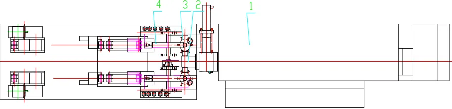
The double station molding device of labyrinth type, single wing drip irrigation belt is shown in Fig. 2.
Fig. 2 Double station molding device of labyrinth type drip irrigation belt 1. Extruder 2. Material distributor 3. Die head 4. Molding wheel
3.1 Design for molding wheel
As shown in Fig. 3, the molding wheel is a complicated runner mold with pre-processed the labyrinth channel, inlet and outlet hole of the drip irrigation belt. The molding wheel comprises a vacuum molding system and a water cooling system, the vacuum tank and water cooling tank are separated. It means that the labyrinth channel is formed by using vacuum plastic molding through molding wheel. The vacuum tank is linked externally to the vacuum pump, so some negative pressure is generated at a specific sector outside the molding wheel. Under the vacuum exsuction effects, the tubular foams in the middle are adsorbed on the surface of the molding wheel. As a result, the labyrinth channel and the drip hole are heat exsuctioned and molded, and then they are cooled with the circulated cooled water outside the molding wheel. In addition, the molding wheel is chrome plated on the surface treatment, for the
Feeding Melting extrusion Material distribution Tube foam molding
Material distributor
Labyrinth molding
Winding Die head
[image:2.595.80.537.480.591.2]Fig. 3 Molding wheel
3.2 Design for die head
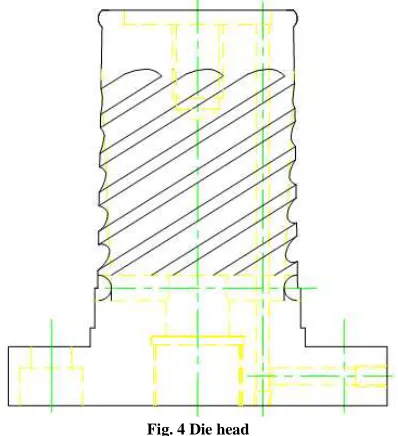
As shown in Fig. 4, the die head adopts the cruciform rectangular structure, while the die channel adopts the design of spiral lines. The movement of the material flow at the spiral mandrel is two-way, circular and axial, movement, forming superimposed layers. This plays a key role in uniformly mixing the materials, which improves the mixing performance of material flow, as well as reduces the fusion line of the material flow. Thus it ensures the uniform extrusion of the materials and makes the tubular foam in uniform thickness.
Fig. 4 Die head
3.3. Design for screw
[image:3.595.207.406.425.643.2]Fig. 5 BM separable screw
3.4. Design for traction component
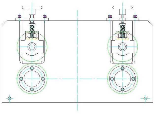
[image:4.595.153.468.200.433.2]The traction component, which is shown in Fig. 6, adopts the design scheme of combing the spring pressing with the rubber wheel traction. Based on the thickness of drip irrigation belt in the process of traction, the springs automatically adjust by floating up and down and are made real-time adjustments according to the fullness of the labyrinth channel of drip irrigation belts.
Fig. 6 Traction component 4 .Experimental verification
4.1. Experimental conditions
Experimental equipment: Double position labyrinth type, single wing drip irrigation belt molding device produced by Zhoushan Ange Machinery Co. Ltd, the model number is AG-DGD-XX-T;
Screw diameter: Φ65mm, the ratio of length to diameter: 30;
Screw material: 38CrMoAlA; Motor power: 37KW; Heating power: 15KW;
Raw material: Recycled polyethylene Screw speed: 90rpm.
RESULTS AND DISCUSSION
4.2. Experimental results
Maximum yield of extruder is 100kg/h, and the speed of production line is 120-140m/min. The thickness of the drip irrigation belt: 0.19mm-0.21mm. It is obviously, the efficiency is increased greatly compared with that of the traditional single wheel molding device. This greatly reduced the floor area, labor cost and electricity consumption. Moreover, the whole device run smoothly in the experimental process, and the noise was less than 78dB. The components of the molding wheel were well sealed, no seepage or leakage. The channel of the drip irrigation belt was uniform and full, its surface was uniform colored and soft, without defects of bulging, depression, roughness or unevenness.
wheel molding device. In addition, the floor area, labor cost and electricity consumption have been considerably
reduced. The size of the drip irrigation belt is stable, its appearance shows no obvious defects, but in good quality;
③ The extruder screw applies the separate structure, and the length of the homogenized segment of the screw is
prolonged. Besides, the diameter of screw groove changes at the reverse compression ratio, the uniform plasticizing melts are produced at high-speed. The die channel adopts the design program of spiral lines, which makes the tube foams in uniform thickness. The labyrinth channel is vacuum plastic molded through the molding wheel.
Acknowledgments
This research work was supported by Program of Education Department of Zhejiang Province (Y201225123), Program for International S&T Cooperation Projects of China (2010DFR50860), National Natural Science Foundation of China (41106077), Program of Science and Technology Department of Zhejiang Province (2012C01014-2, 2012C02001-2), and Program of Science and Technology Department of Zhoushan (2011C12014, 2012C23031, 2013C41003). The supports are gratefully acknowledged.
REFERENCES
[1]Liu Jie, Wei Qingsong, Lu Gang, et al. Water Saving Irrigation. 2009, (7): 40-45.
[2]Nie Jing. Flow field numeric simulation and structural optimization of tooth shape labyrinth flow channel [D].
Urumqi: Xinjiang Agricultural University. 2011.5.
[3]Israel Netafim [OL]. http://www.aquasmart.cn/bencandy.php?fid-19-id-3672-page-1.htm, 2011.11.22.
[4]Instruction of Netafim [OL]. http://netafim3.312green.com/profile-u112577.html.
[5]Mala. GM, Li D Q. International Journal of Heat and Fluid Flow. 1999, 20: 142-148.
[6]Agostini. B, Watel. B. Experimental Thermal Fluid Science. 2004, 28 (2): 97-103.
[7]Zhang Youxin. Plastics Science and Technology. 2010 (9): 55-57.
[8]Zhang Shengjun, Zhai Guoliang, Zhao Huimin, et al. Water Saving Irrigation. 2009 (12): 32-36.