Technology (IJRASET)
Design and Parametric Analysis of Multiband
Directional Antenna for Wireless Applications
K. Shanthalakshmi1, C. Hamsalakshmi2
1
Assistant Professor, 2PG Scholar, Department of ECE, Adhiyamaan College of Engineering, Hosur
Abstract: This paper presents an aperture coupled multiband microstrip antenna for various wireless applications. The antenna consists of microstrip fed slot with a complimentary stub on a single dielectric medium. A reflecting ground plane is employed to achieve unidirectional radiation pattern. This antenna resonates at the frequencies of 4.4GHz, 5.2GHz, 6GHz and7GHz. The proposed antenna is designed by using the substrate Arlon AD410(tm) having relative permittivity of 4.1. The gain of the proposed antenna is above 6dBi and feed of the antenna is optimized to get above 98% of radiation efficiency. Simulations and the parametric analyses of proposed antenna are presented using HFSS software.
Keywords-: aperture coupled, microstrip antenna, multiband, return loss, resonant frequency.
I. INTRODUCTION
The rapid advancement in the field of wireless communication the demand of Microstrip antenna is increased due to its flexibility, robustness, small size and weight, narrow beam of radiation and ease of installation and fabrication .Wireless communication systems have also increased the demand for multiband applications with wideband performance . It means that there is a requirement of antenna to have more than one frequency. Therefore a single antenna with multiband characteristics is more desirable than having one antenna for each frequency band. There are different numbers of approaches to obtain multiband characteristics for planar antennas such as stacked patch configuration, patches with slots and cuts of different shapes. To reduce the size of the antenna the substrate with higher value of dielectric constant should be used . Hence the proposed antenna consists of Arlon AD10(tm) with 4.1 as its dielectric constant and loss tangent of 0.003. Due to its compactness it can be used for WLAN, Radio Altimeter, Mobile and Satellite communications and RADAR applications. High Frequency Structure Simulator (HFSS) is a commercial FEM (Finite Element Method) solver for electromagnetic structures. It is one of the several commercial tools used for antenna design and analysis. This paper presents the design and analysis of multiband directional antenna operating for 4.4GHz, 5.2GHz, 6GHz and 7GHz using HFSS software.
II. ANTENNA DESIGN
A. Directional antenna
A directional antenna is an antenna or an antenna system which can radiate or receive radio signals more effectively in some direction than in others. It allows for increased performance and reduced interferences for unwanted sources.
B. Aperture coupled feeding technique
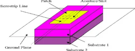
[image:2.612.202.422.625.709.2]In this type of feeding technique, the radiating patch and the microstrip feed line are separated by the ground plane as shown in figure1. Coupling between the patch and feed line is made through a slot or an aperture in the ground plane. The coupling aperture is usually centred under the patch, leading to lower cross polarization due to symmetry of the configuration. The amount of coupling from the feed line to the patch is determined by the shape, size and location of the aperture. Since the ground plane separates patch and feed line, spurious radiations are minimized.
Technology (IJRASET)
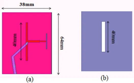
C. Antenna configurationFigure 2 shows the geometry of the proposed antenna. Initially a ground plane with the dimension of 80mm x 80mm with a slot of 40mm x 3.2mm was designed. The slot in the ground plane acts as reflecting plane which is employed to get unidirectional radiation pattern.
Fig. 2 Geometry of the proposed antenna. (a) Top view, (b) Bottom view
The width and length of an efficient radiator can be approximated by using the following formulas.
=
( )− − − − − (1)
= −2∆ − − − − − (2)
Where,
C is the velocity of the light, 3 x 10⁸ m/s.
∈ is the dielectric constant of the substrate, 4.1. is the resonant frequency.
∆ = . ∗ ( . )( . )
. ( . ) − − − − − (3)
= − − − − − (4)
Where,
h is the height of the substrate, Leff is the effective length, ∆ is the extension length,
∈ is the effective relative permittivity.
TABLE I Antenna Dimensions
Parameters Values in mm
Substrate 64 x 38
Slot 40 x 3.2
Strip 40 x 1.5
Strip width 1.5
Feed line length 39
Taper 0.5
Technology (IJRASET)
Fig. 3 Simulated structure of aperture coupled directional antenna
This antenna consists of two layers of substrate. The top layer contains microstrip patch as radiating element. The 50 ohm microstrip feed line is excited with a SMA connector. In order to increase the performance of the antenna such as gain and efficiency, an air gap of height 1mm with ∈ =1 is inserted between top and bottom layer. The air gap is used to avoid coupling problems between aperture slot on ground plane and the microstrip patch on the top layer due to improper alignment between them.
III. RESULTS AND DISCUSSIONS
A. Return Loss
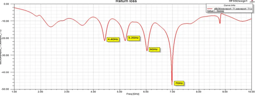
[image:4.612.99.537.464.632.2]The proposed antenna was analysed and optimized with the help of Ansoft HFSS software as shown in Fig.4. Multiband microstrip slot antenna has been achieved in this design. The first band has resonant frequency 4.4GHz with return loss of -21.8 dB. The resonant frequency of second band is 5.2GHz has return loss of -22 dB. The resonant frequency of third band is 6 GHz with return loss of -28 dB. The fourth band has resonant frequency of 7GHz having return loss of -38 dB. The bandwidths of the above frequencies were found to be between 0.8GHz and 1GHz.
Fig. 4 Return loss plot B. Vswr
Technology (IJRASET)
Fig. 5 VSWR plot C. Gain
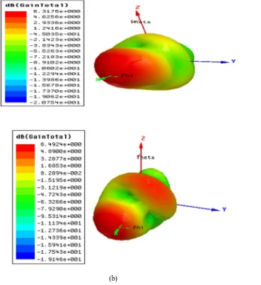
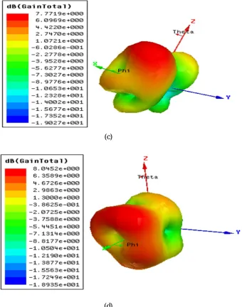
Gain of the antenna gives the measure of the efficiency of the antenna and its directional capabilities. Gain is defined as the ratio of radiation intensity in a particular direction to the radiation intensity obtained if isotropically by the antenna. The gain of the proposed antenna is found to be 6.3176 dB, 6.4924 dB, 7.7719 dB, 8.0452 dB for 4.4GHz, 5.2GHz, 6GHz and 7GHz respectively. The 3D gain plot is shown in Fig.6.
(a)
Technology (IJRASET)
(c)
[image:6.612.175.515.88.520.2](d)
Fig. 6 3D gain plot of proposed antenna. (a) 4.4GHz, (b) 5.2GHz, (c) 6GHz, (d) 7GHz
The different parameters of the proposed antenna and their values are presented in the Table 2. TABLE II
Antenna Parameters
Parameters Simulated results
Frequency 4.4 GHz 5.2 GHz 6 GHz 7 GHz
Return loss (dB) -21 -22 -28 -38
VSWR 1.2 1.19 1.08 1.00
Directivity (dB) 6.4110 6.5433 7.8070 8.0457
Gain (dB) 6.3176 6.4924 7.7719 8.0452
Radiation efficiency 97.8% 98.8% 99.1% 99.9%
Radiation intensity(w/sr)
[image:6.612.70.542.588.715.2]Technology (IJRASET)
IV. CONCLUSION
Thus the proposed directional antenna with multiple frequencies had been designed and simulated for various wireless applications. It is found that proposed structure is widely applicable for wireless communication systems like Radio Altimeter, WLAN, 5G mobile communication, Satellite and RADAR applications. The gain is above 6dBi and VSWR is less than 1.2. The feed of the antenna is optimized to achieve radiation efficiency above 98%. The bandwidth is between 0.8GHz and 1.0GHz. The proposed antenna has good return loss and gain at the frequencies 4.4GHz, 5.2GHz, 6GHz and 7GHz.
REFERENCES [1] K.L Wong, “compact and broadband microstrip antennas” New York: J.Wiley and sons, 2002.
[2] Z.Zaharis, E.Vafiadis and J.N. Sahalos, “On the design of a dual-band base station wire antenna,” IEEE Antennass Propag. Mag., vol.42, no.6, pp. 144-151, Dec 2000.
[3] Inc. NY, USA. Richard Johnson, Henry Jasik, “Antenna Engineering Handbook”, second edition 1984, pp. 7-1 to 7-14, McGraw Hill.
[4] Anil kumar Gautam, Lalit Kumar Kanaujia and Karmudi Rambabu, “Design of compact F-shaped slot triple band antenna for WLAN/WIMAX applications,” IEEE transaction on antennas and propagation, vol, 62, no.3, March 2016.
[5] He Huang Ying Liu, member, IEEE, Shaoshi Zhang, and shuxi Gong, “Multiband metamaterial-loaded monopole antenna for WLAN and WiMAx applications,” IEEE antennas and wireless propagation letters, vol.14, 2014
[6] F.Rashid, M. M. Mustafiz, M. K. Ghosh and S. Hossain, “Design and performance analysis of ultra wideband inverted-F antenna for Wi-Fi, WLAN and military applications,” in 2012 15th international conference on computer and information technology (ICCIT), Chittagong, Dec.2012, pp. 610-614.