A Novel Current Control Technique For A
Three-Phase Statcom
Chitti Spoorthy Reddy1, Durgam Kumara Swamy2, Boini Rajendar3
1,2,3
Dept. of EEE , SVS Institute of Technology , Warangal,Telangana,India
Abstract—This paper proposes an advanced control strategy to enhance performance of shunt active power filter (APF). The proposed control scheme requires only two current sensors at the supply side and does not need a harmonic detector. In order to make the supply currents sinusoidal, an effective harmonic compensation method is developed with the aid of a conventional proportional-integral (PI) and vector PI controllers. The absence of the harmonic detector not only simplifies the control scheme but also significantly improves the accuracy of the APF, since the control performance is no longer affected by the performance of the harmonic tracking process. Furthermore, the total cost to implement the proposed APF becomes lower, owing to the minimized current sensors and the use of a four-switch three-phase inverter. Despite the simplified hardware, the performance of the APF is improved significantly compared to the traditional control scheme, thanks to the effectiveness of the proposed compensation scheme. The proposed control scheme is theoretically analyzed, and a 1.5-kVA APF is built in the laboratory to validate the feasibility of the proposed control strategy.
Index Terms—Active power filters (APFs), harmonic current compensation, power quality, resonant controller.
I. INTRODUCTION
THE INCREASING use of nonlinear loads such as adjustable speed drives, electric arc welders, and switching power supplies causes large amounts of harmonic currents inject into distribution systems. These harmonic currents are responsible for voltage distortion, increasing power losses and heat on networks and transformers, and causing operational failure of electronic equipment. Due to these problems, harmonic restriction standards such as IEEE-519 or IEC 61000-3-2 have been published to demand those harmonic currents injected into utility networks to be below the specified values [1], [2]. In order to improve the power quality of distribution networks as well as to meet these restriction standards, two main solutions have been introduced: LC passive filters an active power filters (APFs) [3]–[5]. LC passive filters are traditionally utilized to compensate the harmonic currents since they are simple and low-cost solution. However, they are often large and heavy. Furthermore, the compensation capability of a passive filter is typically fixed and relies heavily on a network’s impedance, thus potentially causing undesired resonance problems [5].
II. PROPOSED CONTROL STRATEGY TO IMPROVE APF PERFORMANCE
A. Structure Of A Shunt APF
Technology (IJRASET)
Fig. 1.Typical control scheme of a shunt APF.
B. Proposed Control Strategy
In order to simplify the control scheme and to enhance the accuracy of the APF, an advanced control strategy is proposed, as shown in Fig. 2. In Fig. 2, the proposed control scheme is implemented by using only the supply current (iSa and iSb) without detecting the
load current (iL,abc) and filter current (iF,abc). Thereby, the load current sensors and filter current sensors in the typical shunt APF
[image:3.612.212.415.310.450.2]shown in Fig. 1 can be
Fig. 2. Structure of the proposed control scheme for three-phase shunt APF.
eliminated. And also, the harmonic current detection is omitted. Due to the absence of harmonic detection, the proposed control scheme can be implemented with only two loops: the outer voltage control and the inner current control. The outer loop aims to keep dc-link voltage of the APF constant through a PI controller, which helps the APF deal with load variations. The output of this control loop is the reference active current in the fundamental reference frame (i*Sd). Meanwhile, the reference reactive current
(i*Sq) is simply set to be zero, which ensures the reactive power provided by the power supply to be zero. And, the reactive power
caused by loads is supplied by the shunt APF. The inner loop is then used to regulate the supply current in the fundamental reference frame (iS,dq) by using the proposed PI-VPI current controller. The output of this loop becomes the control signal (v*F,ab)
applied to the four-switch APF which is implemented by the FSTPI. Since the current control is executed without the harmonic detector, the control performance of the APF only relies on the current controller. In the next section, the analysis and design of the proposed current controller will be presented.
III. CURRENT CONTROL SCHEME USING PI PLUS VPI CONTROLLERS IN FUNDAMENTAL REFERENCE
FRAME
A. Proposed Current Controller
As illustrated in Fig. 1, harmonic components are detected from the load current by means of the harmonic detector whose output is the reference filter current for the APF. Since the reference filter current is a non-sinusoidal signal, design of current controller for an APF is a challenging task. A series of resonant controllers tuned at harmonic frequencies is typically required for achieving good current performance.
the APF system, it is impossible to force the supply currents to be sinusoidal by using only a PI controller because the supply currents are not directly but indirectly controlled by regulating the filter currents which are the non-sinusoidal signals. In fact, due to the limitation of the control bandwidth, the PI controller is unable to adequately regulate the high frequency signals, e.g., harmonic currents. As a result, the desired control target of the APF cannot be achieved by using only PI current controller. In order to effectively regulate the supply currents to be sinusoidal, the current controller must have high gains at harmonic frequencies, which can be achieved by means of multiple resonant controllers tuned at harmonic frequencies. The transfer function of multiple proportional resonant controllers in the s-domain is given as
where Kph and Krh are the proportional and resonant gains of the resonant controller, respectively, h is the order of harmonic
currents, and ωs is the fundamental frequency of the supply voltage. However, as shown in (1), each resonant controller has a
responsibility to regulate only one harmonic component. Thus, the controller complexity and computational burden are significantly increased if large numbers of harmonic currents are required to be compensated.
In fact, each pair of h = 6n ± 1 harmonic currents behave as h = 6n harmonic currents in the fundamental reference frame. Thus, it is possible to perform a resonant controller tuned at h = 6n multiples of ωs in this reference frame to regulate a pair of h = 6n ± 1
harmonic currents. The transfer function of the PI controller plus resonant controllers in the s-domain is given as
where Kp1 and Ki1 are the proportional and integrator gains of the PI controller, respectively, h = 6n is the order of harmonics in the
fundamental reference frame with n = 1, 2, 3 . . ..
In (2), the aim of the PI controller is to regulate the fundamental current whereas resonant controllers are used to control the harmonic currents. However, the delay time caused by the effect of the APF and digital implementation must be taken into account if the high-order harmonics are compensated. A compensation term is added to (2) to compensate the delay time, the transfer function of the PI-R controller becomes
where N is the number of samples and TS is the sampling period. As described in [17], the best result is obtained when N = 2.
The VPI controller is able to cancel the coupling term with the form1/(sLF + RF ) by selecting the resonant gain as Krh = KphRF /LF ,
where LF and RF are the inductance and the equivalent resistance of the LF inductor, respectively. Owing to this advantage, the VPI
controller is able to remove anomalous peaks appearing in the closed-loop response without demand of delay compensation. Adopting the superiority of the VPI controllers over resonant controllers, VPI controllers given in (4) are used to replace resonant controllers in (2), the transfer function of the proposed PI-VPI current controller in the s-domain is given as follows:
As mentioned earlier, the PI-R controller given in (3) is also able to produce high gains at selected resonant frequencies and overcome the limitation of the PI controller. However, as presented in Fig. 3, undesired peaks appear in the closed-loop frequency response of the PI-R controller when it compensates high-order harmonic components. In contrast, the proposed PI-VPI controller is capable of preventing this problem owing to its pole-zero cancellation capability with the LF inductor.
Technology (IJRASET)
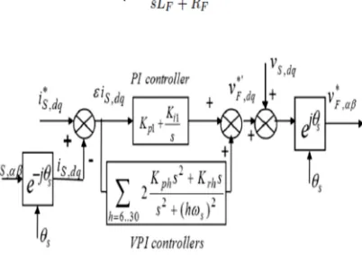
Fig. 3. Block diagram of the proposed current control scheme.
controller. Thus, the use of VPI controllers significantly improves the stability margin and accuracy of the proposed current controller. The complete proposed current control scheme using the PI-VPI controller is shown in Fig. 3. Since the proposed current controller is designed in the fundamental reference frame, the measured supply current iS,αβ first must be transformed from the
stationary to the fundamental reference frame iS,dq. The proposed current controller is then executed to regulate this current follow
its reference i*S,dq. The outputs of the current controllers v*’F,dq and the feed forward supply voltage term vS,dq are added together and
then transformed in the stationary reference frame through an inverse rotational transformation to obtain the command voltage v*F,αβ, which is the control signal for the APF.
B. Current Controller Design
In order to design the gains for the PI-VPI controller and to investigate the effect of these gains on the control performance, the closed-loop transfer function of the PI-VPI current controller defined in (7) is analyzed. By selecting the resonant gain as Krh =
KphRF /LF and Ki1 = Kp1RF /LF, the closed loop transfer function of the PI-VPI controller becomes (8), shown at the bottom of the
page. In (8), Kph and Kp1 are the only gains that need to be tuned. In fact, Kp1 is the integrator gain of the PI controller that does not
affect the harmonic compensation performance of the VPI controller. Thus, for the sake of simplification, Kp1 is kept constant, and
Kph is changed to determine the control performance of the VPI controller.
However, we should not select a too small Kph since it may degrade the dynamic responses of the APF. The controller gains
obtained by using aforementioned design process are kept constant during whole operating time. However, the inductor parameters are changed during operation, so that the relationship,
Krh = KphRF /LF , is no longer satisfied. Fig. 8 shows the Bode diagram of (7) in order to investigate the robustness of the VPI
controller against the inductor parameter variation. As can be seen in Fig. 8, the VPI controller still maintains a unity gain and zero phase-shift at a selected resonant frequency regardless of the different inductor parameter, which means that the inductor parameter variation has no effect on the stability and steady-state performance of the APF.
C. Discrete-Time Implementation Of The VPI Controllers
of the narrow band and infinite gain characteristics of the resonant and VPI controllers, a slight displacement of the resonant poles causes a significant loss of performance. Therefore, the selection of a discretization technique is critical and significantly impacts on the accuracy and control performance of the VPI controllers to achieve accurate resonant pole placement, the transfer function of the VPI controller in the z-domain must be determined as follows:
where z is the shift operator.
The transfer function given in (9) provides an accurate resonant pole placement, but the trigonometric portion of the formula, i.e., the cosine function, must be online calculated and consumes a large amount of execution time as part of the control scheme, particularly when the control algorithm is implemented in low-performance microprocessors or DSPs. So as to avoid this large calculation time, the cosine function is approximated by means of a Taylor series as given by
A higher order approximation results in a more precise result, but an approximation of fourth order also can provide sufficient accuracy and high performance with significantly reduced computation time for the VPI controllers. Therefore, a fourth order approximation is used to replace the cosine function in (9). The transfer function of the VPI controller in the z-domain can now be rewritten as
IV. DESCRIPTION OF THE WHOLE CONTROL STRATEGY
Fig.4 illustrates the block diagram of whole proposed control strategy. As aforementioned, the proposed control scheme contains two main loops: the dc-link voltage control and the supply current control. In addition, since the proposed current\ controller is employed in the fundamental reference frame, a phase-locked loop (PLL) is required to track the phase of the supply voltage which is needed for coordinate transformation and synchronization.
A. DC-Link Voltage Control Loop
As stated earlier, this control loop aims to keep dc-link voltage of the shunt APF constant through a simple PI regulator, whose output is the reference active current in the fundamental reference are reference and measured dc-link voltages of the APF, respectively. In fact, since the four-switch APF has only two switching legs, the four-switch APF needs a higher dc-link voltage reference (V*dc) compared to the traditional six-switch APF as mentioned in Table I. In addition, since the dc-link voltage of the
APF contains small ripples at harmonic frequencies due to harmonic currents, a low-pass filter (LPF) is designed to eliminate all ripples in the feedback measurement of the dc-link voltage, which helps in smoothing the reference current i*Sd. In the proposed
[image:6.612.196.417.610.699.2]control scheme, the role of the dc-link voltage controller is not only to ensure a proper operation of the APF but also to help the APF deal with load variations. In this paper, even though the load current measurement is not used, the load changes can be detected indirectly through dclink voltage variations. Hence, by detecting and regulating the
Technology (IJRASET)
dc-link voltage, the shunt APF can recognize and respond against load variations without the load current measurement.
B. Supply Current Control Loop
This loop regulates the supply current by means of the proposed current control scheme shown in Fig. 5. The reference active current i*Sd is the output of the dc-link voltage control loop given in (13), while the reference reactive current i*Sq is simply set to be
zero. Consequently, the reactive power caused by loads can be fully compensated by the APF, and also unity power factor condition is achieved at the supply side.
C. Control Signal Computation For The Four-Switch APF
The traditional three-phase VSI is commonly used to implement an APF. In this paper, in order to accomplish a low cost APF topology, the four-switch APF is introduced by replacing the traditional three-phase VSI with the FSTPI with- out degrading the performance of the proposed control strategy. The FSTPI, which is composed of four power switching devices and two split capacitors, has been applied for low-cost ac motor drives. In Fig. 9, the control signal in the stationary reference frame (v*F,αβ)
obtained after executing the current controller is changed into control signals of the four-switch APF as the following equations:
Fig. 5. Block diagram of the improved PLL.
D. Supply Voltage PLL
negligible because the PLL usually operates at steady-state condition before the APF is active.
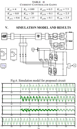
[image:8.612.182.433.104.523.2]V. SIMULATION MODEL AND RESULTS
[image:8.612.186.432.578.697.2]Fig.6. Simulation model for proposed circuit
Fig.7. Dynamic performance of the proposed control scheme-Source current (Isa), Filter current (IFa), Load current (Ila) and Source
voltage (Vsa).
Fig.8. Simulation model for proposed circuit Discrete ,
Ts = 5e -005 s .
po we rgui
v + -A B C + -A B C + -A B C A B C a b c A B C a b c
A B C a b c
A B C a b c A B C a b c A B C A B C
Scopes NOT NOT
g C E g C E g C E g C E Vdc [pulses] From Controller
0 0.05 0.1 0.15 0.2 0.25 0.3 0.35 0.4
-20 0 20
0 0.05 0.1 0.15 0.2 0.25 0.3 0.35 0.4
-1 0 1
0 0.05 0.1 0.15 0.2 0.25 0.3 0.35 0.4
-50 0 50
0 0.05 0.1 0.15 0.2 0.25 0.3 0.35 0.4
-200 0 200
Time
Discre te , T s = 5e -005 s.
powe rgui v + -A B C + -A B C + -A B C A B C a b c A B C a b c A B C a b c A B C a b c
A B C a b c A B C a b c
A B C a b c A B C a b c A B C A B C
S copes NO T NOT
Technology (IJRASET)
Fig.9. Dynamic performance of the proposed control scheme-Source current (Isa), Filter current (IFa), Load current (Ila) and Source
voltage (Vsa).
VI. CONCLUSION
In this paper, an advanced control strategy for the three-phase shunt APF was proposed. The effectiveness of the proposed control strategy was verified through various experimental tests, where the proposed control strategy presented good steady-state performance with nonlinear RL and RLC loads as well as good dynamic response against load variations: the supply current is almost perfect sinusoidal and in-phase with the supply voltage even under the distorted voltage condition. The experimental results verified that the absence of a harmonic detector results in faster transient responses as well as assures notches free in steady-state performances of the supply current. Moreover, we also confirmed that the FSTPI can be used to implement the APF without any degradation in the APF performance. In all of the experiments, THD factor of the supply current was reduced to less than 2%, which completely comply with the IEEE-519 and IEC-61000-3-2 standards.
REFERENCES
[1] Recommended Practice for Harmonic Control in Electric Power Systems, IEEE Std. 519-1992, 1992. [2] Limits for Harmonic Current Emission, IEC 61000-3-2, 2001.
[3] H. Akagi, “New trends in active filters for power conditioning,” IEEE Trans. Ind. Appl., vol. 32, no. 2, pp. 1312–1332, Nov./Dec. 1996. [4] F. Z. Peng, “Application issues of active power filters,” IEEE Ind. Appl. Mag., vol. 4, no. 5, pp. 21–30, Sep./Oct. 1998.
[5] H. Akagi, E. H. Watanabe, and M. Aredes, Instantaneous Power Theory and Applications to Power Conditioning, M. E. El-Hawari, Ed. New York: Wiley, 2007.
0 0.05 0.1 0.15 0.2 0.25 0.3 0.35 0.4
-20 0 20
0 0.05 0.1 0.15 0.2 0.25 0.3 0.35 0.4
-1 0 1
0 0.05 0.1 0.15 0.2 0.25 0.3 0.35 0.4
-50 0 50
0 0.05 0.1 0.15 0.2 0.25 0.3 0.35 0.4
-200 0 200