5
IV
April 2017
Technology (IJRASET)
Synthesis and Flexural Strength of Carbon Fiber
Reinforced Epoxy Matrix Composite
K. Chandra Shekar1, K. Teja2, N. Prashanth3, M. Bharadwaj4, M. V. R. Phanindran5 1
Professor, 2,3,4,5 UG Student, Department of Mechanical Engineering Vignan Institute of Technology and Science, Hyderabad
Abstract: Composite materials are multiphase materials obtained through the judicious combination of different materials in order to attain properties that the individual components by themselves cannot attain. The development of a structural composite materials construction promises to provide a reduced weight and cost solution for the manufacture of components. The composite materials is a light weight structural composite that is obtained by embedding continuous carbon fibers in one or more orientations in a polymer matrix. The fibers provide the strength and stiffness, while the polymer serves as the binder. The carbon fiber polymer matrix composites have attractive properties like low density, high strength, high stiffness, good creep resistance, good fatigue resistance, toughness and damage tolerance. The process of Filament Winding uses a continuous length of fiber strand / roving, or tape results in a shell of materials with a high strength-to-weight ratio due to the high percentage of fiber in the composite matrix (70-80%) patterns may be longitudinal, circumferential, helical or polar mostly requires thermal curing of work pieces. The laminas are taken in required dimensions and are subjected to high temperature curing at constant applied pressure. The flexural test is carried out as per ASTM D790 and it is found that the flexural strength in longitudinal orientation is significantly greater as compared to transverse orientation of fibers.
Keywords: composite, carbon fibers, epoxy matrix, filament winding, flexural strength.
I. INTRODUCTION
Polymer matrix composites (PMC) are being used in many application such as automotive, sporting goods, marine, electrical,
industrial, construction, household appliances, etc., PMC’s have high strength and stiffness, light weight, and high corrosion
resistance. This kind of composites is used in the greatest diversity of composite applications due to its advantages such as low density, good thermal and electrical insulator, ease of fabrication, and low cost [1]. The properties of polymer matrix composites are mainly determined by three constitutive elements such as the types of reinforcements (particles and fibers), the type of polymer, and the interface between them [2]. Compared to non-reinforced polymers most fiber-reinforced polymers are stiffer and less susceptible to fatigue failure and have lower hysteretic heating effects [3]. Polymers are divided into two categories such as thermoplastics and thermosets. Carbon fiber is produced by the controlled oxidation, carbonization and graphitization of carbon-rich organic precursors, which are already in fiber form. [3-4]. The most common precursor is polyacrylonitrile (PAN), because it gives the best carbon fiber properties, but fibers can also be made from pitch or cellulose.
The aim of this experimental study has targeted to optimize the various fabrication parameters and investigate the Flexural strength of carbon fiber reinforced epoxy matrix composites. Flexural strength is one of the most widely used properties in characterizing the mechanical behaviour of composites [5]. Standard test methods are adopted for the flexural property evaluation of composite materials as specified by ASTM at ambient temperatures [6-8]. In the present study, flexural behaviour of the unidirectional carbon fiber reinforced epoxy matrix composite is evaluated in detail in order to determine the influence of orientation of fibers. The results obtained are characterized based mode of failure.
II. EXPERIMENTAL
A. Materials
In this present study LY556 epoxy resin and Arald K6 hardener were used as matrix system. In all structural PMC’s epoxy resin is invariably used as a matrix because of its modulus, chemical inertness and dimensional stability Carbon fiber T300 is used as reinforcing material. The synthesis was concluded by Filament winding technique.
B. Material Processing
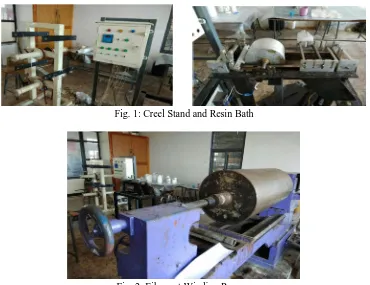
is mounted on to creel stand from which the fiber roving is passed out. The epoxy resin is the primary constituent in the laminate, which is the matrix phase of the composite the hardener acts as a initiator or catalyst for the curing to take place for the formation of laminate. The diluent decreases the viscosity of the resin so that the resin can be impregnated on to a fiber with ease The tension required for the fibers is provided at the creel stand so that the winding process can be carried out without any problem of lose fibers while winding. The resin mixture with the basic constituents of epoxy resin and hardener is prepared for the fabrication process. The epoxy resin, hardener and diluents are measured separately in a small beaker according to the requirement and re thoroughly stirred. The ratio at which the constituents are mixed at 100:27 parts by weight. To prepare the resin mixture all the things required are cleaned thoroughly with acetone to remove the dirt from the apparatus. The epoxy resin mixture is then poured into the bath of 2 liter capacity in which the carbon fiber is impregnated with the resin mixture the carbon fiber roving is mounted on the creel stand as shown in Fig. 1 passed through the provisions provided with a tension applied through resin bath on to the filament winding machine where the drum used for the winding process. The resin bath consists of a drum, a comb, a doctor blade and scraper blade. The doctor blade maintains a uniform thickness of resin over the drum and the fiber is passed over the drum that is partially immersed in the resin mixture. The drum rotates as the fiber is passed over the drum that partially takes resin on to its surface and impresses the carbon fiber with resin. The scraper blade, which is placed after the drum, removes the extra resin from the fiber so that there is a uniform resin distribution over on to the fiber these fibers are wound on the filament winding lathe on a cylindrical drum and are cut to form a sheet. This sheet is cut into several pieces depending upon the required orientations and the number of plies fig. 2 The tool is then placed in a hydraulic press under a pressure of 10 bar for the extraction of undesirable resin along with
the exposure to a second environment with a multi-step increase of temperature with 90oc for one hour, 120o c for 2 hours, 140oc
for 2 hours and 160oc for next 2 hours. The time of polymerization for all samples was 360 min at various temperatures after
samples were formed; test specimens were cutout as per ASTM D790 standard, which were tested.
[image:3.612.122.492.360.645.2]
Fig. 1: Creel Stand and Resin Bath
Fig. 2: Filament Winding Process
C. Flexural Testing
Technology (IJRASET)
Fig. 3: UTM and 3Point Bend Test
The main advantage of a three point flexural test is the ease of the specimen preparation and testing. The test method for conducting the test usually involves a specified test fixture on a universal testing machine. Details of the test preparation, conditioning, and conduct affect the test results. Flexural tests in 3 point bend loading were conducted on unidirectional fiber epoxy composite specimens of rectangular cross sectional area with constant span length of 113.2 mm (16 times the thickness, average thickness of 5.2 mm) in two different orientations i.e., Longitudinal and transverse alignment of fibers to the loading direction. An allowance of 30mm is provided at either ends for support of the specimen. For longitudinal alignment of fibers, 4 specimens were tested and 4 for other alignment. As discussed earlier, the flexural strength can be found according to the following relation:
= 1.5F*L/b*d In the above formula the following parameters are used
f = Flexural strength, (M Pa)
F = load at a given point on the load deflection curve, (N) L = Support span, (mm)
b = Width of test beam, (mm) d = Depth of tested beam ,
III. RESULTS AND DISCUSSIONS
For the sake of accuracy in determination of flexural strength, four specimens were tested experimentally in both longitudinal and transverse orientation of fibers, conforming to ASTM standard D790. For each specimen, the initial dimensions were carefully measured, and then maximum load (F), i.e. the force causing the flexural stress in the specimen, was determined by using Universal Testing Machine. Based upon this value, the geometry of the tested specimen and using the above equation, the flexural strength is found.
A. Flexural Strength in Longitudinal Orientation
Evaluation of flexural strength is carried out when the fibers are aligned longitudinally. Fig. 4 is clearly shows that at approximately 2000N the major fiber bundle fracture has been taken place. Then the composite behaviour showed a stable crack extension and finally the composite failure at a displacement of 6 mm.in this orientation the average flexural strength 733.7920466 M pa. The specifications of the specimen and flexural strength values are given in table.1
[image:4.612.201.404.584.697.2]Test results for carbon fiber reinforced composites in longitudinal orientation is as shown below
Table.1: Flexural values of various carbon fiber reinforced composite specimens in longitudinal direction
B. Flexural Strength in Transverse Orientation
Flexural strength is also carried out when the fibers are in transverse orientation. Fig. 5 is clearly shows that at approximately 460N fracture has been taken place. In contrast to longitudinally oriented samples, Here the failure has taken place suddenly i.e. there is no stable crack extension during the failure of composite. The average flexural strength of transverse specimen is found to 243.9451772 M pa
[image:5.612.205.395.281.389.2]Test results for carbon fiber reinforced composites in Transverse orientation are shown in table.2
[image:5.612.61.572.548.690.2]Fig. 5: Load Vs. Displacement data for Transverse specimen
Table 4.2: Flexural values of various carbon fiber reinforced composite specimens in transverse direction
C. Effect of Directionality
Fig. 6 Comparison of both longitudinal and transverse specimens
Specimen Width(mm) Thickness(mm) Length(mm) Maximum
load(N)
Flexural strength (M Pa)
FS-L1 10.43 5.31 113.2 1800 780.0185254
FS-L2 11.4 5.44 113.2 2000 773.993808
FS-L3 10.63 5.30 113.2 1680 715.6676547
FS-L4 9.78 5.90 113.2 1600 665.488198
Specimen Width(mm) Thickness(mm) Length(mm) Maximum
load(N)
Flexural Strength (M Pa)
FS-T1 10.58 5.68 113.2 400 159.7486621
FS-T2 10.34 5.64 113.2 480 197.5389934
FS-T3 11.63 5.59 113.2 800 295.3314557
FS-T4 11.21 5.30 113.2 800 323.1615976
transverse longitudinal 0
500 1000
specimen 1specimen 2
specimen 3
specimen 4
transverse
Technology (IJRASET)
From the above plots showing Load Vs Displacement for both directions, some of the points are derived. The composite material in longitudinal orientation of fibers possesses significant flexural strength when compared to transverse orientation of fibers. This is attributed to unidirectional weaving of carbon fibers. In transverse orientation the flexural strength is found to be significantly lower due negligible participation of fibers. From fig. 4 and 5 it is also found that the failure of material in longitudinal orientation.The material in transverse direction yields poor results due to the direct matrix cracking. The failure of the material in longitudinal orientation has taken over a wider displacement rang as compared transverse specimen the failure takes place in narrow displacement range as shown in fig. 6.
D. Factography
All the above results were correlated by using scanning electron micrographic study. Fig. 7 clearly shows that crack propagation is perpendicular to the orientation of fibers.it is also observed that some degree of fiber pullout and good bonding between epoxy matrix and carbon fiber. This leads to higher values of flexural strength in longitudinal orientation. whereas in transverse orientation there is no resistance to the propagation of crack i.e. crack propagation is along the length of the fibers fig. 8. This resulted the lower values of flexural strength in transverse orientation
Fig. 7 SEM images of Longitudinal specimens
Fig. 8 SEM images of Transverse specimens
IV. CONCLUSIONS
A. The flexural strength of longitudinal specimens is three times higher as compared to transverse orientation of fibers. This is
due to crack propagation resistance offered by the fibers in longitudinal orientation, where as in transverse orientation matrix bears the load. This resulted in very poor values.
B. From the factographic studies it is found that the significantly higher values in longitudinal orientation due to the crack bridging
mechanism i.e., fiber pullout during failure.
C. It is also found that there is good bonding between epoxy matrix and carbon fibers.
REFERENCES
[1] Vinay H B,” processing and characterization of glass fiber and carbon fiber reinforced vinyl ester based composites” H K Govindaraju, Prashanth Banakar,2015
[2] T.A. Osswald, G. Menges, Materials Science of Polymers for Engineers, 2nd Edition, Hanser Publishers, Munich, 2003 [3] K.CHANDRA SHEKAR,” Processing, structure and flexural strength of CNT and carbon fiberreinforced, epoxy-matrix hybrid composite” M SAI PRIYA, P
K SUBRAMANIAN, ANIL KUMAR,B ANJANEYA PRASAD, N ESWARA PRASAD,2014 [4] M.S. Sham Prasad,’ Experimental Methods of Determining Fracture Toughness of Fiber Reinforced Polymer Composites under Various Loading Conditions
C.S. Venkatesha, T. Jayaraju , 2011 [5] Chandra Shekar K, “ Fabrication and flexural strength of glass fiber reinforced epoxy matrix composite”, IJSRD, 2016
[6] ASTM Standard D 3171-11 Standard test methods for constituent content of composite materials; Annual Book of ASTM Standards (West Conshohocken,PA: American Society for Testing and Materials) [7] ASTM Standard D 790-10 Test Methods for Flexural Properties of Unreinforced and Reinforced Plastics and Electrical Insulating Materials Annual Book of
ASTM Standards American Society for Testing and Materials, West Conshohocken, [8] Chandra Shekar K, Naveen Kumar M, Subramanian P K, Anil Kumar, Anjaneya Prasad B and Eswara Prasad N 2013 Trans.Indian Inst Metals. doi: 10.1007/s