6
I
January 2018
Effect of Earthquake Load on Column Forces in
Concrete Frame Structures with Different Type of
RC Shear Walls under Different Type of Soil
Condition
Mahdi Hosseini1, Prof.N.V.Ramana Rao2
1Ph.D. scholar student in Structural Engineering, Dept. of Civil Engineering, Jawaharlal Nehru Technological University
Hyderabad (JNTUH), Hyderabad, Telangana , India
2Professor, Dept. of Civil Engineering, Jawaharlal Nehru Technological University Hyderabad (JNTUH), Hyderabad, & Director
of National Institute of Technology Warangal ,Telangana, India
Abstract: Shear Wall is A Structural Element Used to Resist Lateral, Horizontal, Shear Forces Parallel to the Plane of the Wall by Cantilever Action For Slender Walls Where The Bending Deformation Is Dominant .Truss Action For Squat/Short Walls Where The Shear Deformation is Dominant.Shear walls are analyzed to resist two types of forces: shear forces and uplift forces. Shear forces are created throughout the height of the wall between the top and bottom shear wall connections. Uplift forces exist on shear walls because the horizontal forces are applied to the top of the wall. These uplift forces try to lift up one end of the wall and push the other end down. In some cases, the uplift force is large enough to tip the wall over. Shear walls are analyzed to the provide necessary lateral strength to resist horizontal forces. Shear walls are strong enough, to transfer these horizontal forces to the next element in the load path below them. The seismic motion that reaches a structure on the surface of the earth is influenced by local soil conditions. The subsurface soil layers underlying the building foundation may amplify the response of the building to earthquake motions originating in the bedrock. Three types soil are considered here:Hard soil ,Medium soil,soft soil. In the present work thirty story building with C Shape,Box shape,E Shape,I shape and Plus shape RC Shear wall at the center in Concrete Frame Structure with fixed support conditions under different type of soil for earthquake zone V as per IS 1893 (part 1) : 2002 in India are analyzed using software ETABS by Dynamic analysis. All the analyses has been carried out as per the Indian Standard code books. This paper aims to Study the effect of Seismic load on Column Forces in Different Type of RC Shear Walls in Concrete Frame Structures under Different Type of Soil Condition. Estimation of Column Forces such as; Column Axial Force , Column moment, Column shear Force , Column Torsion, Time period and frequency and Modal Load Participation Ratios is carried out. In dynamic analysis; Response Spectrum method is used.
Keywords:- Dynamic Analysis ,Column Forces , Soft ,Medium &Hard Soil, Time period , frequency and Modal Load Participation Ratios, C,Box,E,I and Plus shapes RC Sher wall, software ETABS
I. INTRODUCTION
A. Shear Wall Structure
The usefulness of shear walls in framing of buildings has long been recognized. Walls situated in advantageous positions in a building can form an efficient lateral-force-resisting system, simultaneously fulfilling other functional requirements. When a permanent and similar subdivision of floor areas in all stories is required as in the case of hotels or apartment buildings, numerous shear walls can be utilized not only for lateral force resistance but also to carry gravity loads. In such case, the floor by floor repetitive planning allows the walls to be vertically continuous which may serve simultaneously as excellent acoustic and fire insulators between the apartments. Shear walls may be planar but are often of L-, T-, I-, or E,C,Box shaped section to better suit the planning and to increase their flexural stiffness.
most desirable locations for shear walls in order to optimize seismic resistance. The major structural considerations for individual shear walls will be aspects of symmetry in stiffness, torsional stability and available overturning capacity of the foundations (Paulay and Priestley, 1992).
B. Earthquake Load
The seismic weight of building is the sum of seismic weight of all the floors. The seismic weight of each floor is its full dead load plus appropriate amount of imposed load, the latter being that part of the imposed loads that may reasonably be expected to be attached to the structure at the time of earthquake shaking. It includes the weight of permanent and movable partitions, permanent equipment, a part of the live load, etc. While computing the seismic weight of columns and walls in any storey shall be equally distributed to the floors above and below the storey. Earthquake forces experienced by a building result from ground motions (accelerations) which are also fluctuating or dynamic in nature, in fact they reverse direction some what chaotically. The magnitude of an earthquake force depends on the magnitude of an earthquake, distance from the earthquake source(epicenter), local ground conditions that may amplify ground shaking (or dampen it), the weight(or mass) of the structure, and the type of structural system and its ability to with stand abusive cyclic loading. In theory and practice, the lateral force that a building experiences from an earthquake increases in direct proportion with the acceleration of ground motion at the building site and the mass of the building (i.e., a doubling in ground motion acceleration or building mass will double the load).This theory rests on the simplicity and validity of Newton’s law of physics: F = m x a, where ‘F’ represents force, ‘m’ represents mass or weight, and ‘a’ represents acceleration. For example, as a car accelerates forward, a force is imparted to the driver through the seat to push him forward with the car(this force is equivalent to the weight of the driver multiplied by the acceleration or rate of change in speed of the car). As the brake is applied, the car is decelerated and a force is imparted to the driver by the seat-belt to push him back toward the seat.Similarly, as the ground accelerates back and forth during an earthquake it imparts back-and-forth(cyclic) forces to a building through its foundation which is forced to move with the ground. One can imagine a very light structure such as fabric tent that will be undamaged in almost any earthquake but it will not survive high wind. The reason is the low mass (weight) of the tent. Therefore, residential buildings generally perform reasonably well in earthquakes but are more vulnerable in high-wind load prone areas. Regardless, the proper amount of bracing is required in both cases.
C. Shear Wall Components
Reinforced concrete and reinforced masonry shear walls are seldom-simple walls. Whenever a wall has doors, windows, or other openings, the wall must be considered as an assemblage of relatively flexible components like column segments and wall piers and relatively stiff elements like wall segments
1) Column segments: A column segment is a vertical member whose height exceeds three times its thickness and whose width is less than two and one-half times its thickness. Its load is usually predominantly axial. Although it may contribute little to the lateral force resistance of the shear wall is rigidity must be considered. When a column is built integral with a wall, the portion of the column that project from the face the wall is called a pilaster. Column segments shall be designed according to ACI 318 for concrete.
2) Wall piers: A wall pier is a segment of a wall whose horizontal length is between two and one-half and six times its thickness whose clear height is at least two times its horizontal length.
3) Wall segments: Wall segments are components that are longer than wall piers. They are the primary resisting components in the shear wall.
D. Importance Of Seismic Design Codes
Such forces and deformations. Seismic codes help to improve the behavior of structures so that may withstand the earthquake effect without significant loss of life and property. Countries around the world have procedures outlined in seismic code to help design engineers in the planning, designing, detailing and constructing of structures.
E. An Earthquake Resistant Has Four Virtues In it, Namely
1) Good Structural Configuration: its size, shape and structural system carrying loads are such that they ensure a direct and smooth flow of inertia forces to the ground.
3) Adequate Stiffness: Its lateral load resisting system is such that the earthquake – indeed deformations in it do not damage its contents under low-to- moderate shaking.
4) Good Ductility: Its capacity to undergo large deformations under severe earthquake shaking even after yielding is improved by favorable design and detailing strategies.
E. Indian Seismic Codes
Seismic codes are unique to a particular region or country. They take into account the local seismology, accepted level of seismic risk, buildings typologies, and materials and methods used in construction.
The Bureau of Indian Standards (BIS) the following Seismic Codes:
IS 4326, 1993, Indian Standard Code of practice for Earthquake Resistant Design and Construction of Buildings. (2nd revision). IS 13827, 1993, Indian Standard Guidelines for improving Earthquake Resistant of Earthen buildings.
IS 13828, 1993 Indian Standard Guidelines for improving Earthquake Resistant of Low Strength Masonry Buildings.
IS 13920, 1993, Indian Standard Code for practice for Ductile Detailing of Reinforced Concrete Structures Subjected to Seismic Forces.
The regulations in these standards do not ensure that structures suffer no damage during earthquake of all magnitude. But, to the extent possible, they ensure that structures are able to respond to earthquake shaking of moderate intensities without structural damage and of heavy intensities wit out total collapse.
F. Site Selection
The seismic motion that reaches a structure on the surface of the earth is influenced by local soil conditions. The subsurface soil layers underlying the building foundation may amplify the response of the building to earthquake motions originating in the bedrock.
For soft soils the earthquake vibrations can be significantly amplified and hence the shaking of structures sited on soft soils can be much greater than for structures sited on hard soils. Hence the appropriate soil investigation should be carried out to establish the allowable bearing capacity and nature of soil. The choice of a site for a building from the failure prevention point of view is mainly concerned with the stability of the ground. The very loose sands or sensitive clays are liable to be destroyed by the earthquake, so much as to lose their original structure and thereby undergo compaction. This would result in large unequal settlements and damage the building. If the loose cohesion less soils are saturated with water they are likely to lose their shear resistance altogether during ground shaking. This leads to liquefaction. Although such soils can be compacted, for small buildings the operation may be too costly and the sites having these soils are better avoided.
For large building complexes, such as housing developments, new colonies, etc. this factor should be thoroughly investigated and the site has to be selected appropriately. Therefore a site with sufficient bearing capacity and free from the above defects should be chosen and its drainage condition improved so that no water accumulates and saturates the ground especially close to the footing level.
G. Bearing capacity of foundation soil Three soil types are considered here:
with IS: 1888-1982 load test (Revision 1992). It is a common practice to increase the allowable bearing pressure by one-third, i.e. 33%, while performing seismic analysis of the materials like massive crystalline bedrock sedimentary rock, dense to very dense soil and heavily over
nuclear reactor containment structures, interaction effects can be important, even for relatively firm soils because the important parameter apparently is not the stiffness of the soil, but the relative stiffness of the building and its foundation. In terms of the dynamic properties of the building foundation system, past studies have shown that the interaction will, in general, reduce the fundamental frequency of the system from that of the structure on a rigid base, dissipate part of the vibrational energy of the building by wave radiation into the foundation medium and modify the base motion of the structure in comparison to the free- field motion. Although all these effects may be present in some degree for every structure, the important point is to establish under what conditions the effects are of practical significance.
II. METHODOLOGY
Earthquake motion causes vibration of the structure leading to inertia forces. Thus a structure must be able to safely transmit the horizontal and the vertical inertia forces generated in the super structure through the foundation to the ground. Hence, for most of the ordinary structures, earthquake-resistant design requires ensuring that the structure has adequate lateral load carrying capacity. Seismic codes will guide a designer to safely design the structure for its intended purpose.
Quite a few methods are available for the earthquake analysis of buildings; two of them are presented here: A. Equivalent Static Lateral Force Method (pseudo static method).
B. Dynamic analysis
C. Response spectrum method D. Time history method.
E. Equivalent lateral Force (Seismic Coefficient) Method
This method of finding lateral forces is also known as the static method or the equivalent static method or the seismic coefficient method. The static method is the simplest one and it requires less computational effort and is based on formulae given in the code of practice.
In all the methods of analyzing a multi storey buildings recommended in the code, the structure is treated as discrete system having concentrated masses at floor levels which include the weight of columns and walls in any storey should be equally distributed to the floors above and below the storey. In addition, the appropriate amount of imposed load at this floor is also lumped with it. It is also assumed that the structure flexible and will deflect with respect to the position of foundation the lumped mass system reduces to the solution of a system of second order differential equations. These equations are formed by distribution, of mass and stiffness in a structure, together with its damping characteristics of the ground motion.
F. Dynamic Analysis
Dynamic analysis shall be performed to obtain the design seismic force, and its distribution in different levels along the height of the building, and in the various lateral load resisting element, for the following buildings:
Regular buildings: Those greater than 40m in height in zones IV and V, those greater than 90m in height in zone II and III.
Irregular buildings: All framed buildings higher than 12m in zones IV and V, and those greater than 40m in height in zones II and II The analysis of model for dynamic analysis of buildings with unusual configuration should be such that it adequately models the types of irregularities present in the building configuration. Buildings with plan irregularities, as defined in Table 4 of IS code: 1893-2002 cannot be modeled for dynamic analysis.
Dynamic analysis may be performed either by the TIME HISTORY METHOD or by the RESPONSE SPECTRUM METHOD
G. Time History Method
The usage of this method shall be on an appropriate ground motion and shall be performed using accepted principles of dynamics. In this method, the mathematical model of the building is subjected to accelerations from earthquake records that represent the expected earthquake at the base of the structure.
H. Response Spectrum Method
to occur during a major earthquake, implying that an inelastic analysis is more proper for design. However, in spite of the availability of nonlinear inelastic programs, they are not used in typical design practice because:
Their proper use requires knowledge of their inner workings and theories. design criteria, and Result produced are difficult to interpret and apply to traditional design criteria , and The necessary computations are expensive.
Therefore, analysis in practice typically use linear elastic procedures based on the response spectrum method. The response spectrum analysis is the preferred method because it is easier to use.
III. LITERATURE REVIEW
Generally, the building configuration which is conceived by architects and then accepted by developer or owner may provide a narrow range of options for lateral-load resistant systems that can be utilized by structural engineers. By observing the following fundamental principles relevant to seismic responses, more suitable structural systems may be adopted (Paulay and Priestley, 1992): To perform well in an earthquake, a building should possess simple and regular configurations. Buildings with articulated plans such as T and L shapes should be avoided.
Symmetry in plans should be provided, wherever possible. Lack of symmetry in plan may lead to significant torsional response, the reliable prediction of which is often difficult.
An integrated foundation system should tie together all vertical structural elements in both principal directions. Foundation resting on different soil condition should preferably be avoided.
Lateral force resisting systems with significantly different stiffness such as shear walls and frames within one building should be arranged in such a way that at every level of the building, symmetry in lateral stiffness is not grossly violated. Thus, undesirable torsional effects will be minimized.
Regularity in elevation should prevail in both the geometry and the variation of story stiffness.
hat S.M. et al., (2013) carried out study on Eathquake behaviour of buildings with and without shear walls. Parameters like Lateral isplacement, story drift etc were found and compared with the bare frame model.
Sagar K.et al., (2012) carried out linear dynamic analysis on two sixteen storey high buildings.It was concluded that shear walls are one of the most effective building elements in resisting lateral forces during earthquake. Providing shear walls in proper position minimizes effect and damages due to earthquake and winds.
Kumbhare P.S. et al., (2012) carried out a study on shear wall frame interaction systems and member forces. It was found that shear wall frame interaction systems are very effective in resisting lateral forces induced by earthquake. Placing shear wall away from center of gravity resulted in increase in the most of the members forces. It follows that shear walls should be coinciding with the centroid of the building.
Based on the literature review, the salient objective of the present study have been identified as follows:
A. behaviour of high rise structure with dual system with Different Type of RC Shear Walls (C, E,I,Boxand Plus shapes) with seismic loading.
B. To examine the effect of different types of soil (Hard, medium and Soft) on the overall interactive behaviour of the shear wall foundation soil system.
C. The variation of maximum Column Axial Force , Column moment, Column shear Force and Column Torsion of the models has been studied.
D. The variation of Time period and frequency has been studied. E. The variation of Modal Load Participation Ratios has been studied.
IV. MODELING OF BUILDING
A. Details of The Building
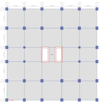
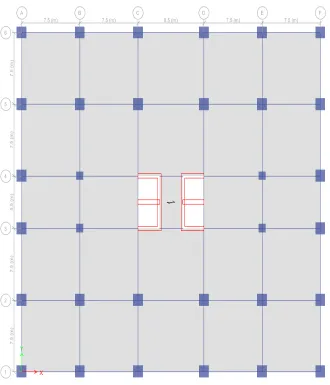
A symmetrical building of plan 38.5m X 35.5m located with location in zone V, India is considered. Four bays of length 7.5m& one bays of length 8.5m along X - direction and Four bays of length 7.5m& one bays of length 5.5m along Y - direction are provided. Shear Wall is provided at the center core of building model.
2) Structure 2 : In this model building with 30 storey is modeled as (Dual frame system with shear wall (Box Shape) at the center of building ,The shear wall acts as vertical cantilever.
3) Structure 3 : In this model building with 30 storey is modeled as (Dual frame system with shear wall (C- Shape ) at the center of building, The shear wall acts as vertical cantilever.
4) Structure 4 : In this model building with 30 storey is modeled as (Dual frame system with shear wall (E- Shape ) at the center of building ,The shear wall acts as vertical cantilever.
5) Structure 5 : In this model building with 30 storey is modeled as (Dual frame system with shear wall (I- Shape) at the center of building, The shear wall acts as vertical cantilever.
B. Load Combinations
As per IS 1893 (Part 1): 2002 Clause no. 6.3.1.2, the following load cases have to be considered for analysis: 1.5 (DL + IL)
1.2 (DL + IL ± EL) 1.5 (DL ± EL) 0.9 DL ± 1.5 EL
[image:7.612.78.531.307.734.2]Earthquake load must be considered for +X, -X, +Y and –Y directions.
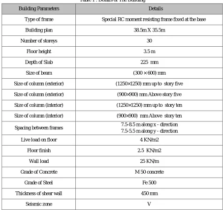
Table 1 : Details of The Building
Building Parameters Details
Type of frame Special RC moment resisting frame fixed at the base
Building plan 38.5m X 35.5m
Number of storeys 30
Floor height 3.5 m
Depth of Slab 225 mm
Size of beam (300 × 600) mm
Size of column (exterior) (1250×1250) mm up to story five
Size of column (exterior) (900×900) mm Above story five
Size of column (interior) (1250×1250) mm up to story ten
Size of column (interior) (900×900) mm Above story ten
Spacing between frames 7.5-8.5 m along x - direction 7.5-5.5 m along y - direction
Live load on floor 4 KN/m2
Floor finish 2.5 KN/m2
Wall load 25 KN/m
Grade of Concrete M 50 concrete
Grade of Steel Fe 500
Thickness of shear wall 450 mm
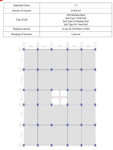
Important Factor 1.5
Density of concrete 25 KN/m3
Type of soil
Soft,Medium,Hard Soil Type I=Soft Soil Soil Type II=Medium Soil
Soil Type III= Hard Soil
Response spectra As per IS 1893(Part-1):2002
[image:8.612.67.535.66.683.2]Damping of structure 5 percent
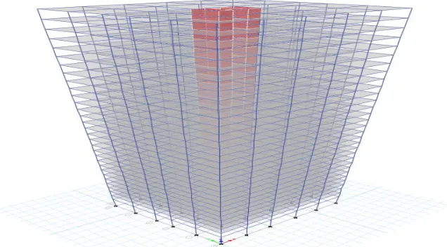
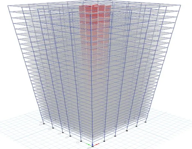
Figure 2. 3D view showing shear wall locationfor Structure 1
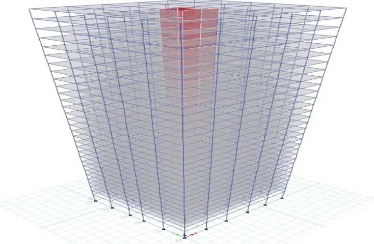
Figure 4. 3D view showing shear wall location for Structure2
[image:10.612.138.472.291.706.2]Figure 6. 3D view showing shear wall location for Structure 3
[image:11.612.138.468.317.702.2]Figure 8. 3D view showing shear wall location for Structure 4
[image:12.612.113.503.365.716.2]Figure 10. 3D view showing shear wall location for Structure 5
V. RESULTS AND DISCUSSIONS
[image:13.612.38.577.408.737.2]A. Column Forces
Table 2: column axial force, P for structures with the load combination 1.2 (DL+LL+EQXP) &1.2 (DL+LL+EQYP) in soft soil TABLE: Column
Forces
Structur e -1
Structure -2
Structure -3 Structure -4 Structure -5 Stor y Colum n Uniqu e Name Load Case/Combo Statio n
P P P P P
m kN kN kN kN kN
1ST C34 67 12DLRLLEQ XP
0
-24171.0618 -24285.049
3
-24629.8602 -24381.544
4
-24398.177
3 1ST C34 67 12DLRLLEQ
XP
1.45 -24103.093 -24217.080
6
-24561.8915 -24313.575
7
-24330.208
6 1ST C34 67 12DLRLLEQ
XP
2.9
-24035.1243 -24149.111
8
-24493.9227 -24245.606
9
-24262.239
8 1ST C34 67 12DLRLLEQ
YP
0
-23630.6382 -23276.171
1
-23447.6424 -23345.175
2
-23441.164
9 1ST C34 67 12DLRLLEQ
YP
1.45 -23562.6694
-23208.202
3
-23379.6736 -23277.206
5
-23373.196
1 1ST C34 67 12DLRLLEQ
YP
2.9
-23494.7007 -23140.233
6
-23311.7049 -23209.237
7
-23305.227
Table 3: column axial force, P for structures with the load combination 1.2 (DL+LL+EQXP) &1.2 (DL+LL+EQYP) in medium soil TABLE: Column Forces Structure -1 Structure -2 Structure -3 Structure -4 Structure -5
Story Column Unique Name Load Case/Combo
Station P P P P P
m kN kN kN kN kN
1ST C34 67 12DLRLLEQXP 0
-24937.4993 -25121.0698 -25571.6279 -25446.3503 -25240.6514 1ST C34 67 12DLRLLEQXP 1.45
-24869.5305 -25053.1011 -25503.6591 -25378.3816 -25172.6826
1ST C34 67 12DLRLLEQXP 2.9
-24801.5618 -24985.1323 -25435.6904 -25310.4128 -25104.7139
1ST C34 67 12DLRLLEQYP 0
-24202.5232 -23748.9954 -23963.8116 -23949.6572 -23939.1144 1ST C34 67 12DLRLLEQYP 1.45
-24134.5545 -23681.0267 -23895.8428 -23881.6884 -23871.1456
1ST C34 67 12DLRLLEQYP 2.9
-24066.5857 -23613.0579 -23827.8741 -23813.7197 -23803.1769
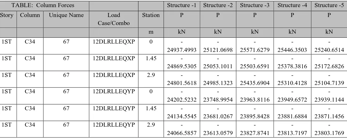
Table 4: column axial force, P for structures with the load combination 1.2 (DL+LL+EQXP) &1.2 (DL+LL+EQYP) in hard soil TABLE: Column Forces Structure
-1 Structure -2 Structure -3 Structure -4 Structure -5 Stor y Colum n
Unique Name Load Case/Combo
Statio n
P P P P P
m kN kN kN kN kN
1ST C34 67 12DLRLLEQX P
0
-25597.487 1 -25840.976 4 -26382.594 4 -26235.548 2 -25966.115 1 1ST C34 67 12DLRLLEQX
P
1.45 -25529.518 4 -25773.007 6 -26314.625 7 -26167.579 4 -25898.146 4 1ST C34 67 12DLRLLEQX
P
2.9 -25461.549 6 -25705.038 9 -26246.656 9 -26099.610 7 -25830.177 6 1ST C34 67 12DLRLLEQY
P
0
-24694.979 8 -24156.149 7 -24408.290 6
-24397.697 -24367.904
3 1ST C34 67 12DLRLLEQY
P
1.45 -24627.011 -24088.181 -24340.321 9 -24329.728 3 -24299.935 5 1ST C34 67 12DLRLLEQY
P
[image:14.612.37.579.348.663.2]Table 5:column Moment, M for structures with the load combination 1.2 (DL+LL+EQXP) &1.2 (DL+LL+EQYP) in soft soil
TABLE: Column Forces Structure -1 Structure -1 Structure
-2
Structure -2 Structure -3 Structure -3 Structure -4 Structure -4 Structure -5 Structure -5
Story Column Unique Name
Load Case/Combo Station M2 M3 M2 M3 M2 M3 M2 M3 M2 M3
m kN-m kN-m kN-m kN-m kN-m kN-m kN-m kN-m kN-m kN-m
1ST C34 67 12DLRLLEQXP 0 -244.0118 979.4715 -171.6774 1061.1112 -251.8641 1421.2435 -239.9922 1271.7973 -249.7758 971.7283
1ST C34 67 12DLRLLEQXP 1.45 -146.2684 805.6993 -84.4168 912.7196 -151.3927 1219.8181 -142.186 1095.4925 -150.8748 826.9906
1ST C34 67 12DLRLLEQXP 2.9 -48.5251 631.9271 2.8438 764.328 -50.9213 1018.3927 -44.3799 919.1878 -51.9738 682.2529
1ST C34 67 12DLRLLEQYP 0 1727.5733 -24.7075 1026.407 -134.6353 1218.6199 -173.1854 1153.6344 -157.4043 1174.9664 -74.8523
1ST C34 67 12DLRLLEQYP 1.45 1393.6416 -70.5194 893.9723 -94.628 1027.4053 -112.2758 974.8851 -107.0072 954.7475 -81.4083
1ST C34 67 12DLRLLEQYP 2.9 1059.71 -116.3313 761.5375 -54.6207 836.1907 -51.3663 796.1358 -56.6101 734.5287 -87.9644
[image:15.612.13.601.575.716.2]Table 6: column Moment, M for structures with the load combination 1.2 (DL+LL+EQXP) &1.2 (DL+LL+EQYP)in medium soil
TABLE: Column Forces Structure -1 Structure -1 Structure
-2
Structure -2 Structure -3
Structure -3 Structure -4 Structure -4
Structure -5 Structure -5
Story Column Unique Name
Load Case/Combo Station M2 M3 M2 M3 M2 M3 M2 M3 M2 M3
m kN-m kN-m kN-m kN-m kN-m kN-m kN-m kN-m kN-m kN-m
1ST C34 67 12DLRLLEQXP 0 -312.5242 1329.5266 -216.79 1461.8423 -325.8538 1958.0803 -325.927 1862.7469 -322.5699 1328.7543
1ST C34 67 12DLRLLEQXP 1.45 -197.6708 1112.7719 -115.9939 1264.1942 -207.082 1683.6228 -206.7527 1610.877 -205.9796 1142.9081
1ST C34 67 12DLRLLEQXP 2.9 -82.8175 896.0172 -15.1978 1066.5461 -88.3102 1409.1652 -87.5785 1359.0072 -89.3893 957.0619
1ST C34 67 12DLRLLEQYP 0 2368.8316 -36.1568 1412.6049 -164.3729 1674.0045 -210.3429 1686.2828 -200.7817 1615.0795 -94.5952
1ST C34 67 12DLRLLEQYP 1.45 1896.6069 -78.8855 1214.6153 -105.7985 1396.0833 -128.025 1406.1652 -125.3418 1297.6668 -92.5144
1ST C34 67 12DLRLLEQYP 2.9 1424.3822 -121.6142 1016.6256 -47.2242 1118.1621 -45.707 1126.0477 -49.9019 980.2541 -90.4336
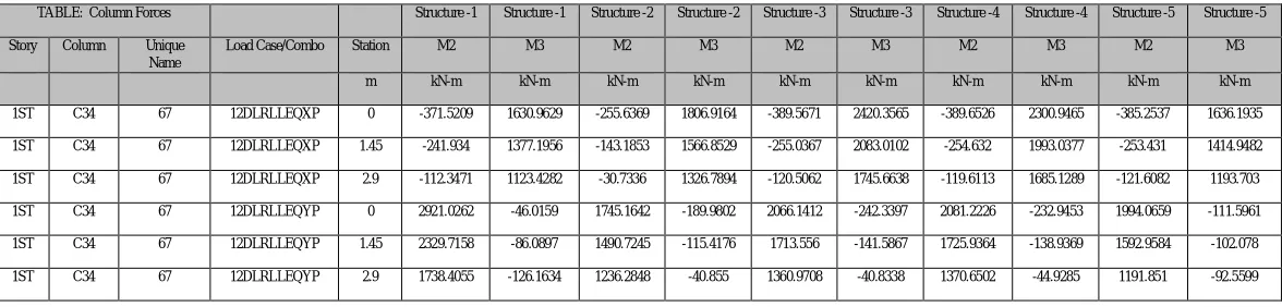
Table 7: Column Moment, M for structures with the load combination 1.2 (DL+LL+EQXP) &1.2 (DL+LL+EQYP) in hard soil
TABLE: Column Forces Structure -1 Structure -1 Structure -2 Structure -2 Structure -3 Structure -3 Structure -4 Structure -4 Structure -5 Structure -5
Story Column Unique Name
Load Case/Combo Station M2 M3 M2 M3 M2 M3 M2 M3 M2 M3
m kN-m kN-m kN-m kN-m kN-m kN-m kN-m kN-m kN-m kN-m
1ST C34 67 12DLRLLEQXP 0 -371.5209 1630.9629 -255.6369 1806.9164 -389.5671 2420.3565 -389.6526 2300.9465 -385.2537 1636.1935
1ST C34 67 12DLRLLEQXP 1.45 -241.934 1377.1956 -143.1853 1566.8529 -255.0367 2083.0102 -254.632 1993.0377 -253.431 1414.9482
1ST C34 67 12DLRLLEQXP 2.9 -112.3471 1123.4282 -30.7336 1326.7894 -120.5062 1745.6638 -119.6113 1685.1289 -121.6082 1193.703
1ST C34 67 12DLRLLEQYP 0 2921.0262 -46.0159 1745.1642 -189.9802 2066.1412 -242.3397 2081.2226 -232.9453 1994.0659 -111.5961
1ST C34 67 12DLRLLEQYP 1.45 2329.7158 -86.0897 1490.7245 -115.4176 1713.556 -141.5867 1725.9364 -138.9369 1592.9584 -102.078
Table 8:column Shear, V for structures with the load combination 1.2 (DL+LL+EQXP) &1.2 (DL+LL+EQYP)in soft soil TABLE: Column Forces Structure -1 Structure -1 Structure -2 Structure -2 Structure
-3
Structure -3
Structure -4 Structure -4 Structure -5
Structure -5 Story Column Unique
Name
Load Case/Combo Station V2 V3 V2 V3 V2 V3 V2 V3 V2 V3
m kN kN kN kN kN kN kN kN kN kN
1ST C34 67 12DLRLLEQXP 0 119.8429 -67.4092 102.339 -60.1798 138.9141 -69.2906 121.5895 -67.4525 99.8191 -68.2076
1ST C34 67 12DLRLLEQXP 1.45 119.8429 -67.4092 102.339 -60.1798 138.9141 -69.2906 121.5895 -67.4525 99.8191 -68.2076
1ST C34 67 12DLRLLEQXP 2.9 119.8429 -67.4092 102.339 -60.1798 138.9141 -69.2906 121.5895 -67.4525 99.8191 -68.2076
1ST C34 67 12DLRLLEQYP 0 31.5944 230.2977 -27.5912 91.3343 -42.0066 131.8722 -34.7566 123.2754 4.5214 151.8751
1ST C34 67 12DLRLLEQYP 1.45 31.5944 230.2977 -27.5912 91.3343 -42.0066 131.8722 -34.7566 123.2754 4.5214 151.8751
1ST C34 67 12DLRLLEQYP 2.9 31.5944 230.2977 -27.5912 91.3343 -42.0066 131.8722 -34.7566 123.2754 4.5214 151.8751
Table 9: column Shear, V for structures with the load combination 1.2 (DL+LL+EQXP) &1.2 (DL+LL+EQYP)in medium soil
TABLE: Column Forces Structure
-1 Structure -1 Structure -2 Structure -2 Structure -3 Structure -3 Structure -4 Structure -4 Structure -5 Structure -5 Story Column Unique
Name
Load Case/Combo Station V2 V3 V2 V3 V2 V3 V2 V3 V2 V3
m kN kN kN kN kN kN kN kN kN kN
1ST C34 67 12DLRLLEQXP 0 149.486 -79.2092 136.3091 -69.5145 189.2811 -81.9116 173.7034 -82.1892 128.1698 -80.4071
1ST C34 67 12DLRLLEQXP 1.45 149.486 -79.2092 136.3091 -69.5145 189.2811 -81.9116 173.7034 -82.1892 128.1698 -80.4071
1ST C34 67 12DLRLLEQXP 2.9 149.486 -79.2092 136.3091 -69.5145 189.2811 -81.9116 173.7034 -82.1892 128.1698 -80.4071
1ST C34 67 12DLRLLEQYP 0 29.4681 325.6722 -40.3961 136.5446 -56.771 191.6698 -52.0275 193.1845 -1.435 218.9053
1ST C34 67 12DLRLLEQYP 1.45 29.4681 325.6722 -40.3961 136.5446 -56.771 191.6698 -52.0275 193.1845 -1.435 218.9053
[image:16.612.18.598.417.557.2]1ST C34 67 12DLRLLEQYP 2.9 29.4681 325.6722 -40.3961 136.5446 -56.771 191.6698 -52.0275 193.1845 -1.435 218.9053
Table 10:column Shear, V for structurse with the load combination 1.2 (DL+LL+EQXP) &1.2 (DL+LL+EQYP) in hard soil TABLE: Column Forces Structure -1 Structure -1 Structure -2 Structure -2 Structure
-3
Structure -3
Structure -4
Structure -4 Structure -5
Structure -5 Story Column Unique
Name
Load Case/Combo Station V2 V3 V2 V3 V2 V3 V2 V3 V2 V3
m kN kN kN kN kN kN kN kN kN kN
1ST C34 67 12DLRLLEQXP 0 175.012 -89.3703 165.561 -77.5528 232.6527 -92.7796 212.3509 -93.1177 152.5829 -90.9122
1ST C34 67 12DLRLLEQXP 1.45 175.012 -89.3703 165.561 -77.5528 232.6527 -92.7796 212.3509 -93.1177 152.5829 -90.9122
1ST C34 67 12DLRLLEQXP 2.9 175.012 -89.3703 165.561 -77.5528 232.6527 -92.7796 212.3509 -93.1177 152.5829 -90.9122
1ST C34 67 12DLRLLEQYP 0 27.6371 407.8002 -51.4225 175.4757 -69.4848 243.1622 -64.8334 245.025 -6.5642 276.6258
1ST C34 67 12DLRLLEQYP 1.45 27.6371 407.8002 -51.4225 175.4757 -69.4848 243.1622 -64.8334 245.025 -6.5642 276.6258
[image:16.612.46.580.589.725.2]1ST C34 67 12DLRLLEQYP 2.9 27.6371 407.8002 -51.4225 175.4757 -69.4848 243.1622 -64.8334 245.025 -6.5642 276.6258
Table 11:column Torsion, T for structures with the load combination 1.2 (DL+LL+EQXP) &1.2 (DL+LL+EQYP) in soft soil
TABLE: Column Forces Structure -1 Structure -2 Structure -3 Structure -4 Structure -5
Story Column Unique Name Load Case/Combo Station T T T T T
m kN-m kN-m kN-m kN-m kN-m
1ST C34 67 12DLRLLEQXP 0 -41.6175 -29.3334 -44.901 -42.3525 -43.8436
1ST C34 67 12DLRLLEQXP 1.45 -41.6175 -29.3334 -44.901 -42.3525 -43.8436
1ST C34 67 12DLRLLEQXP 2.9 -41.6175 -29.3334 -44.901 -42.3525 -43.8436
1ST C34 67 12DLRLLEQYP 0 45.3145 31.9525 48.8724 46.1375 48.5638
1ST C34 67 12DLRLLEQYP 1.45 45.3145 31.9525 48.8724 46.1375 48.5638
Table 12: column Torsion, T for structures with the load combination 1.2 (DL+LL+EQXP) &1.2 (DL+LL+EQYP)in medium soil
TABLE: Column Forces Structure -1 Structure -2 Structure -3 Structure -4 Structure -5
Story Column Unique Name Load
Case/Combo
Station T T T T T
m kN-m kN-m kN-m kN-m kN-m
1ST C34 67 12DLRLLEQXP 0 -56.5981 -39.8539 -61.0208 -61.1008 -59.584
1ST C34 67 12DLRLLEQXP 1.45 -56.5981 -39.8539 -61.0208 -61.1008 -59.584
1ST C34 67 12DLRLLEQXP 2.9 -56.5981 -39.8539 -61.0208 -61.1008 -59.584
1ST C34 67 12DLRLLEQYP 0 61.6294 43.4949 66.5111 66.66 66.09
1ST C34 67 12DLRLLEQYP 1.45 61.6294 43.4949 66.5111 66.66 66.09
1ST C34 67 12DLRLLEQYP 2.9 61.6294 43.4949 66.5111 66.66 66.09
Table 13:column Torsion, T for structures with the load combination 1.2 (DL+LL+EQXP) &1.2 (DL+LL+EQYP)in hard soil TABLE: Column Forces Structure
-1
Structure -2 Structure -3 Structure -4 Structure -5 Stor y Colum n Unique Name Load Case/Combo
Station T T T T T
m kN-m kN-m kN-m kN-m kN-m
1ST C34 67 12DLRLLEQX P
0 -69.4981 -48.9132 -74.9017 -75.004 -73.1383
1ST C34 67 12DLRLLEQX P
1.45 -69.4981 -48.9132 -74.9017 -75.004 -73.1383
1ST C34 67 12DLRLLEQX P
2.9 -69.4981 -48.9132 -74.9017 -75.004 -73.1383
1ST C34 67 12DLRLLEQY P
0 75.6784 53.4342 81.6999 81.8788 81.182
1ST C34 67 12DLRLLEQY P
1.45 75.6784 53.4342 81.6999 81.8788 81.182
1ST C34 67 12DLRLLEQY P
2.9 75.6784 53.4342 81.6999 81.8788 81.182
TABLE 14: Modal Load Participation Ratios
TABLE: Modal Load Participatio n Ratios structur e 1 Structur e 1 Structur e 2 Structur e 2 Structur e 3 Structur e 3 Structur e 4 Structur e 4 Structur e 5 Structur e 5
Case Item Type Ite
m
Static Dynami
c
Static Dynami
c
Static Dynami
c
Static Dynami
c
Static Dynami
c
% % % % % % % % % %
Modal Acceleratio
n
UX 99.82 86.71 99.99 94.7 99.98 94.59 99.99 94.54 99.97 91.54
Modal Acceleratio
n
UY 99.79 87.46 99.98 91.46 99.97 91.85 99.97 91.83 99.97 92.51
Modal Acceleratio
n
A plot for Modal Load Participation Ratios of Structures in Soft Soil, Medium Soil and Hard Soil has been shown here
`
[image:18.612.43.576.358.733.2]Graph 1: Modal Load Participation Ratios of Structures in Soft Soil , Medium Soil and Hard Soil
Table 15: Modal Periods and Frequencies Structure -1 Structur
e -2 Structure -2 Structure -3 Structure -3 Structur e -4 Structure -4 Structur e -5 Structure -5 Case Mod
e
Perio d
Frequenc y
Period Frequenc y
Period Frequenc y
Period Frequenc y
Period Frequenc y sec cyc/sec sec cyc/sec sec cyc/sec sec cyc/sec sec cyc/sec
Moda l
1 6.298 0.159 5.785 0.173 6.415 0.156 6.375 0.157 6.382 0.157
Moda l
2 6.248 0.16 5.606 0.178 6.32 0.158 6.21 0.161 5.694 0.176
Moda l
3 5.545 0.18 4.684 0.213 5.767 0.173 5.792 0.173 5.642 0.177
Moda l
4 2.062 0.485 1.701 0.588 2.114 0.473 2.102 0.476 2.088 0.479
Moda l
5 1.952 0.512 1.547 0.646 1.958 0.511 1.901 0.526 1.565 0.639
Moda l
6 1.603 0.624 1.475 0.678 1.568 0.638 1.575 0.635 1.524 0.656
Moda l
7 1.191 0.84 0.9 1.112 1.219 0.82 1.212 0.825 1.19 0.84
Moda l
8 1.027 0.974 0.838 1.193 1.028 0.972 0.983 1.017 0.791 1.264
Moda l
9 0.803 1.245 0.645 1.551 0.82 1.22 0.815 1.226 0.711 1.406
Moda l
10 0.782 1.279 0.613 1.632 0.711 1.406 0.714 1.401 0.703 1.423
Moda l
11 0.645 1.55 0.5 2.002 0.641 1.56 0.604 1.656 0.565 1.769 0 5 10 15 20 25 30 35 40 45 50 55 60 65 70 75 80 85 90 95 100 105 % % % % % % % % % %
Static Dynamic Static Dynamic Static Dynamic Static Dynamic Static Dynamic
structure -1 Structure -1 Structure -2 Structure -2 Structure -3 Structure -3 Structure -4 Structure -4 Structure -5 Structure -5 % o f A cc el e ra ti o n Structures
Modal Load Participation Ratios
Moda l
12 0.581 1.72 0.45 2.222 0.592 1.689 0.589 1.697 0.423 2.363
IV. DISCUSSION ON RESULTS
When a structure is subjected to earthquake, it responds by vibrating. An example force can be resolved into three mutually perpendicular directions- two horizontal directions (X and Y directions) and the vertical direction (Z). This motion causes the structure to vibrate or shake in all three directions; the predominant direction of shaking is horizontal. All the structures are primarily designed for gravity loads-force equal to mass time’s gravity in the vertical direction. Because of the inherent factor used in the design specifications, most structures tend to be adequately protected against vertical shaking. Vertical acceleration should also be considered in structures with large spans those in which stability for design, or for overall stability analysis of structures. The basic intent of design theory for earthquake resistant structures is that buildings should be able to resist minor earthquakes without damage, resist moderate earthquakes without structural damage but with some non-structural damage. To avoid collapse during a major earthquake, Members must be ductile enough to absorb and dissipate energy by post elastic deformation. Redundancy in the structural system permits redistribution of internal forces in the event of the failure of key elements. When the primary element or system yields or fails, the lateral force can be redistributed to a secondary system to prevent progressive failure.
The structures are supported on soil, most of the designers do not consider the soil structure interaction and its subsequent effect on structures during an earthquake. When a structure is subjected to an earthquake excitation, it interacts with the foundation and the soil, and thus changes the motion of the ground. This means that the movement of the whole ground-structure system is influenced by the type of soil as well as by the type of structure. Understanding of soil structure interaction will enable the designer to design structures that will behave better during an earthquake. The Axial force and Moment in the column increases when the type of soil changes from hard to medium and medium to soft. Since the column moment increase as the soil type changes, soil structure interaction must be suitably considered while designing frames for seismic force.
The result obtained from the analysis models will be discussed and compared as follows:
A. It Is Observed That
1) The Time Period is 6.298 Sec for structure1 and it is same for different type of soil. 2) The Frequency is 0.159 cyc/sec for structure1 and it is same for different type of soil. 3) The Time Period is 5.785 Sec for structure2 and it is same for different type of soil. 4) The Frequency is 0.173 cyc/sec for structure2 and it is same for different type of soil. 5) The Time Period is 6.415 Sec for structure3 and it is same for different type of soil. 6) The Frequency is 0.156 cyc/sec for structure3 and it is same for different type of soil. 7) The Time Period is 6.375Sec for structure4 and it is same for different type of soil. 8) The Frequency is 0.157 cyc/sec for structure4 and it is same for different type of soil. 9) The Time Period is 6.382 Sec for structure5 and it is same for different type of soil. 10) The Frequency is 0.157 cyc/sec for structure5 and it is same for different type of soil.
B. It Is Observed That Column Forces For Structure 1
The maximum column axial force is various with type of soil and placing of the shear wall. The Value of column axial force in soft soil>medium soil>hard soil.
The Value of maximum column Torsion , T in Y-direction for soft Soil <Medium soil < Hard soil.
C. It Is Observed That Column Forces For Structure 2
The maximum column axial force is various with type of soil and placing of the shear wall. The Value of Column axial force in soft soil>medium soil>hard soil.
The maximum column moment in Y-direction is influenced by the type of soil and placing of shear wall. The Value of maximum column moment M2 in X-direction for soft Soil >Medium soil > Hard soil. The Value of maximum column moment M3 in X-direction for soft Soil >Medium soil > Hard soil. The Value of maximum column moment M2 in Y-direction for soft Soil <Medium soil < Hard soil. The Value of maximum column moment M3in Y-direction for soft Soil >Medium soil > Hard soil. The Value of maximum column Shear V2 in X-direction for soft Soil <Medium soil < Hard soil. The Value of maximum column Shear V3 in X-direction for soft Soil >Medium soil > Hard soil. The Value of maximum column Shear V2 in Y-direction for soft Soil>Medium soil > Hard soil. The Value of maximum column Shear V3 in Y-direction for soft Soil <Medium soil < Hard soil. The Value of maximum column Torsion , T in X-direction for soft Soil >Medium soil > Hard soil. The Value of maximum column Torsion , T in Y-direction for soft Soil <Medium soil < Hard soil.
D. It Is Observed That Column Forces For Structure 3
The maximum column axial force is various with type of soil and placing of the shear wall. The Value of Column axial force in soft soil>medium soil>hard soil.
The maximum column moment in Y-direction is influenced by the type of soil and placing of shear wall. The Value of maximum column moment M2 in X-direction for soft Soil >Medium soil > Hard soil. The Value of maximum column moment M3 in X-direction for soft Soil <Medium soil < Hard soil. The Value of maximum column moment M2 in Y-direction for soft Soil <Medium soil < Hard soil. The Value of maximum column moment M3in Y-direction for soft Soil >Medium soil > Hard soil. The Value of maximum column Shear V2 in X-direction for soft Soil <Medium soil < Hard soil. The Value of maximum column Shear V3 in X-direction for soft Soil >Medium soil > Hard soil. The Value of maximum column Torsion , T in X-direction for soft Soil >Medium soil > Hard soil. The Value of maximum column Torsion , T in Y-direction for soft Soil <Medium soil < Hard soil.
E. It Is Observed That Column Forces For Structure 4
The column axial force is various with type of soil and placing of the shear wall. The Value of column axial force in soft soil>medium soil>hard soil.
The column moment in Y-direction is influenced by the type of soil and placing of shear wall. The Value of column moment M2 in X-direction for soft Soil >Medium soil > Hard soil. The Value of column moment M3 in X-direction for soft Soil <Medium soil < Hard soil. The Value of column moment M2 in Y-direction for soft Soil <Medium soil < Hard soil. The Value of column moment M3in Y-direction for soft Soil >Medium soil > Hard soil. The Value of column Shear V2 in X-direction for soft Soil <Medium soil < Hard soil. The Value of column Shear V3 in X-direction for soft Soil >Medium soil > Hard soil. The Value of column Shear V2 in Y-direction for soft Soil >Medium soil > Hard soil. The Value of column Shear V3 inY-direction for soft Soil <Medium soil <Hard soil. The Value of column Torsion T, in X-direction for soft Soil >Medium soil > Hard soil. The Value of column Torsion T, in Y-direction for soft Soil <Medium soil < Hard soil.
F. It Is Observed That Column Forces For Structure 5
The maximum column axial force is various with type of soil and placing of the shear wall. The Value of column axial force in soft soil>medium soil>hard soil.
The Value of maximum column moment M3 in X direction for soft Soil <Medium soil < Hard soil. The Value of maximum column moment M2 in Y direction for soft Soil <Medium soil < Hard soil. The Value of maximum column moment M3in Y direction for soft Soil >Medium soil > Hard soil. The Value of maximum column Shear V2 in X-direction for soft Soil <Medium soil < Hard soil. The Value of maximum column Shear V3 in X-direction for soft Soil >Medium soil > Hard soil. The Value of maximum column Shear V2 in Y-direction for soft Soil>Medium soil > Hard soil. The Value of maximum column Shear V3 in Y-direction for soft Soil <Medium soil < Hard soil. The Value of maximum column Torsion , T in X direction for soft Soil >Medium soil > Hard soil. The Value of maximum column Torsion , T in Ydirection for soft Soil <Medium soil < Hard soil.
VI. CONCLUSIONS
In this paper, reinforced concrete shear wall buildings were analyzed with the procedures laid out in IS codes. Seismic performance of building model is evaluated.
From the above results and discussions, following conclusions can be drawn:
A. The shear wall and it is position has a significant influenced on the time period. The time period is not influenced by the type of soil.
B. It is observed that the maximum column axial force is various with type of soil and placing of the shear wall.
C. It is observed that the maximum column shear force in x-direction is influenced by the type of soil and placing of the shear wall.
D. It is observed that the maximum column shear force in y-direction has no influence on the type of soil and placing shear wall. E. It is observed that the maximum column torsion is same for all columns in a structure, but is influenced by the type of soil and
placing shear wall.
F. It is observed that the maximum column moment in x-direction has no influence on the type of soil and placing shear wall. G. It is observed that the maximum column moment in y-direction is influenced by the type of soil and placing of shear wall. H. The Axial force and Moment in the column increases when the type of soil changes from hard to medium and medium to soft.
Since the column moment increase as the soil type changes, soil structure interaction must be suitably considered while designing frames for seismic force.
I. The moment resisting frame with shear walls are very good in lateral force such as earthquake and wind force. The shear walls provide lateral load distribution by transferring the wind and earthquake loads to the foundation. And also impact on the lateral stiffness of the system and also carries gravity loads.
J. It is evident that shear walls which are provided from the foundation to the rooftop, are one of the excellent mean for providing earthquake resistant to multistory reinforced building with different type of soil.
K. The vertical reinforcement that is uniformly distributed in the shear wall shall not be less than the horizontal reinforcement .This provision is particularly for squat walls (i.e. Height-to-width ratio is about 1.0).However ,for walls whit height-to-width ratio less than 1.0, a major part of the shear force is resisted by the vertical reinforcement. Hence ,adequate vertical reinforcement should be provided for such walls.
L. Based on the analysis and discussion ,shear wall are very much suitable for resisting earthquake induced lateral forces in multistoried structural systems when compared to multistoried structural systems whit out shear walls. They can be made to behave in a ductile manner by adopting proper detailing techniques.
M. According to IS-1893:2002 the number of modes to be used in the analysis should be such that the total sum of modal masses of all modes considered is at least 90 percent of the total seismic mass. Here the maximum mass for structure 2 is 94.7 percent and minimum mass for structure 1 is 86.71 percent.
REFERENCES
[1] Duggal, S.K., “Earthquake Resistant Design of Structures” Oxford University Press, New Delhi 2010
[2] Chopra, A.K., “Dynamics of Structures: Theory and Application to Earthquake Engineering”, Pearson Education, 4th edition, 2012. [3] Bureau of Indian Standars, IS 456 : 2000, “Plain and Reinforced Concrete-Code of practice”, New Delhi, India.
[5] Bureau of Indian Standards: IS 875( part 1) : 1987, “Dead loads on buildings and Structures”, New Delhi, India. [6] Bureau of Indian Standards: IS 875( part 2 ) : 1987, “Live loads on buildings and Structures”,New Delhi, India.
[7] Bureau of Indian Standards: IS 1893 (part 1) : 2002, “Criteria for earthquake resistant design of structures: Part 1 General provisions and buildings”, New Delhi, India.
[8] Berkeley “ETABS Integrated Building Design Software”, Computers and Structure, Inc., California, USA, February 2003.
[9] Gary R.scarer and Sigmund A.Freeman " Design drifts requirement for long period structures " , 1 3 ' World conference on earth quake engineering Vancouver,B.C, anada ,Aug 2004 paper no-3292 .
[10] J.L.Humar and S.Yavari "Design of concrete shear wall buildings for earthquake induced torsion". 4'1" structural conference of the Canadian society for civil engineering June-2002.
[11] Mo and Jost ,“the seismic response of multistory reinforced concrete framed shear walls using a nonlinear model” , Volume 15, Structure Engineering , Issue 3, 1993, Pages 155–166
[12] Paulay,T., and Priestley, M.J.N., ‘Seismic design of reinforced concrete and masonry buildings’, 1992.
[13] Anand, N. , Mightraj, C. and Prince Arulraj, G. “Seismic behaviour of RCC shear wall under different soil conditions” Indian geotechnical conference, Dec – 2010, pp 119-120
[14] Anshuman, S., Dipendu Bhunia, Bhavin Ramjiyani,“Solution of shear wall location in multistory building”, International journal of civil and structural engineering, Vol. 4, Issue 5, pp. 22-32 ,2011.
[15] Chandiwala, A., “Earthquake Analysis of Building Configuration with Different Position of Shear Wall”, International Journal of Emerging Technology and Advanced Engineering ISSN 2250-2459, ISO 9001:2008 Certified Journal, Volume 2, Issue 12, December 2012
[16] Chandurkar, P.P., Dr. Pajgade, P.S., “Seismic analysis of RCC building with and without shear wall”, International Journal of Modern Engineering Research. Vol. 3, Issue 3, pp. 1805-1810, 2013.