Technology (IJRASET)
Evaluation of System Parameters on Electrical
Machine Bearings through Reduced order models
M.Venu Gopal#1, G.Devanand*2
1
Department of Mathematics, 2,Department of EEE LIMAT
Abstract - This paper examines ac motor shaft voltages and resulting bearing currents when operated under Pulse Width Modulation (PWM) voltage source inverters. A brief view of a system model for electrical analysis of bearing currents and the propensity for Electric Discharge Machining (EDM) is determined by a design equation that is a function of system components. Pertinent machine parameters and their formulas are presented and values calculated for machines from 5 to 1000 Hp. The effects of system elements on shaft voltages and bearing currents are evaluated experimentally and the results compared to theory. Finally, this paper will present quantitative results for one solution to the shaft voltage and bearing current problem. Keywords – PWM,EDM,Second oredr differential equations.
I. INTRODUCTION
Drive systems engineers typically concern themselves with the distribution of developed motor torque. An analysis of mechanical components (e.g., motor bearings) seldom is of interest. However, the presence of Insulated Gate Bipolar Transistors (IGBTs) and higher carrier frequencies require the design engineer to be aware of the effects of Pulse Width Modulation (PWM) waveforms on the system mechanical components. Recently, investigators observed the existence of significant shaft voltages induced by PWM
voltage source inverters. The values exceed those associated with magnetic dissymetries reported on by Alger and others over three quarters of century ago.
The effect these voltages can have on the bearing race surfaces. With the continuing increase in bearing life through improvements in mechanical design troubling because recent bearing failures have shown to be the result of Electrostatic Discharge Machining (EDM); voltage breakdown of the lubricant with coincident gap discharge.
More recent investigators include Costello and Lawson. They reported on shaft voltage and bearing current problems, but were primarily concerned with magnetically induced bearing currents. Possible mechanisms for bearing damage when operating on Variable Frequency Drives (VFD) are dv/dt or electrostatically induced currents, oil film dielectric breakdown causing EDM
currents, and current causing chemical changes within the lubricant. A recent investigation was conducted by Chen, et al., on this
EDM phenomenon . Recently, the authors presented their findings on EDM and its relationship to PWM inverter operation [6,7]. The authors suggested the sources for Rotor Shaft to Ground Voltage (Vrg) include electrostatic charge build up and capacitive coupling. These studies resulted in an electrical model of the inverter, motor, and bearing system, and the development of an Electrostatic Shielded Induction Motor (ESIM), a solution to the electrostatically induced bearing damage.The electrical model accurately predicted the Vrg and bearing currents measured when operating with PWM Voltage Source Inverters (VSI). The electrical system model consists of a balanced three phase source with a common mode or zero sequence source from neutral to ground and two sets of balanced three phase impedances coupled by an equivalent p network of machine capacitances. The zero sequence or common mode equivalent circuit. The bearing model combines a bearing resistance in series with the parallel combination of the Bearing Capacitance (Cb) and a nonlinear device; the device accounts for the random charging and discharging of the rotor shaft. This paper further examines the zero sequence model and explains the electrical factors driving the shaft voltage coupling mechanism. Motor capacitance formulas are presented and values calculated for a range of horsepower ratings. Effects of machine parameters and interface components (e.g.,common mode chokes, cables) are examined analytically and compared with experimental results. The paper shows second and third order reduced models accurately predict the frequency response and damping factor of the Vrg and system current. Experimental results suggest bearing current densities with PWM VSI drives can exceed bearing life thresholds.Finally, results employing an ESIM and identical system interface components show the efficacy of the ESIM in reducing rotor voltage build up.
II. THE COMMON MODE EQUIVALENT CIRCUIT
Technology (IJRASET)
of Fig. 2 provides accurate results without the complexity of the distributed system. The common mode models for the ac machine, cable, common mode chokes,transformers, and line reactors are included in the figure. Although greatly simplified, the equivalent circuit provides a useful tool for the analysis of system parameters and their effect on Vrg and bearing current.
It is clear the existence of dv/dt and EDM bearing currents with PWM VSI drives depends on the following three conditions: (1) a source of excitation (Vsg),which is transferred by the zero sequence or common mode components to the Stator Neutral to Ground Voltage (Vsng),(2) a capacitive coupling mechanism, accomplished by the Stator to Rotor Capacitance (Csr), and (3) sufficient Vrg
buildup, a random occurrence depending on the existence of Cb. All three of these conditions must simultaneously exist for EDM
currents to occur.
This section of the paper will explore the system factors contributing to the development of Vrg buildup. Part A develops the machine components with Cb calculations based on results by researchers in Tribology. Following the presentation of relevant mechanical properties, machine capacitance formulas are derived for the components in Fig.2. Part B examines experimental evaluations of the model parameters and compares the values to the design
A. Capacitance Calculations for the Shaft Voltage and Bearing Current Model Mechanical Components - Cb
The occurrence of Vrg and bearing currents depends on the existence of Cb. Furthermore, the bearing impedance becomes capacitive only when a lubricant film occurs in the contact regions between the balls or rollers and the raceways. The minimum film thickness is given by:
H0 = 2.65U0.7g0.54 /Q0.13……. (1)
where U is a function of the fluid velocity and viscosity, g a function of the pressure coefficient of viscosity and modulus of elasticity, and Q the force or load acting on the ball or roller . Other factors influencing the Cb include the temperature (T), viscosity (h), additives, lubricant film thickness relationship to the rms value of the contact surface (L),and dielectric strength of the lubricant (er).The dielectric strength of lubricants is determined by static tests . Data provided by lubricant vendors indicates dielectric strengths range from 1 to 30 kV/mm. These values reflect dielectric strengths of films on the order of millimeters. However, typical bearing loads together with (1) and measured data indicate lubricant film thickness ranges from 0.2 to 2.0 microns. These values are significantly lower than those employed by the static tests. Based on tests, that 15 Vpk/mm dielectric strength is reasonable.
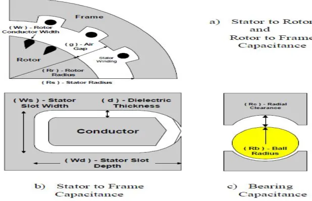
[image:3.612.154.463.503.702.2]This suggests shaft voltages from 3 to 30 volts can produce EDM currents. Furthermore, tests performed on the 15 Hp induction motor of showed a maximum withstand voltage of 30 volts peak at pulse duration's of 10 msecs. Thus, Cb becomes a complicated function of all the above variables (Cb(Q, er,U,T,h,l,L )) .Electrical Components - Lo, Ro, Csf, Csr, Crf Although a distributed parameter system, lumped parameters adequately model the system .This system consists of the stator winding zero sequence impedance (Lo and Ro), the Stator winding to Frame Capacitance (Csf), Csr, the Rotor to Frame Capacitance (Crf), and Cb. A formula for each capacitance follows, together with calculations for machines from 5 to 1000 horsepower. These formulas assume the geometrical shapes depicted in Fig. 1
Technology (IJRASET)
Calculation of Csf :The Csf model consisted of Ns parallel capacitors, where Ns is the number of stator slots. Each slot consisted of a conductor Ls meters long, Wd meters deep, and Ws meters wide centered within a rectangular conduit with all sides at the same potential. A dielectric material separates the conductor and conduit by d meters with a relative permittivity of er (slot paper). Equation (2) provides the Csf for Ns slots . The calculated values of Csf for induction machines from 5 to 1000 Hp.
Csf = Ksf Ns er eo (Wd + Ws)L s / d …… (2)
Calculation of Csr: The stator to rotor coupling capacitance,shown in Fig. 3, consists of Nr sets of parallel conducting plates. The area of each plate equals the product of the length of the rotor (Lr) and the width of the rotor conductor near the rotor surface (Wr). This capacitance is given by (3); where the distance between the parallel plates (g) is the air gap of the machine.The calculated Csr
for induction machines from 5 to 1000 Hp.
Csr = Ksr Nr eoWr Lr / g……. (3)
Calculation of Crf: The capacitive coupling between the rotor and frame, shown in Fig. 3, is determined as the capacitance of two concentric cylinders or a coaxial capacitor. In this case, the effective gap between the cylinders must compensate for the effect of the stator slot widths. If the inside radius of the outer cylinder (stator) is Rs and the outer radius of the inner cylinder (rotor) Rr, then the capacitance is given by the calculated Crf for induction machines from 5 to 1000 Hp.
Crf = Krf peoLr / ln (Rs /Rr) ……(4)
Calculation of Cb: The bearing capacitance depends on the geometrical configuration of the bearing, load, speed, temperature, and characteristics of the lubricant. Each bearing type - ball, roller, journal, etc. - yields a capacitance model, with the capacitance value a function of physical and operating parameters. For example, a journal bearing's capacitance increases with increasing eccentricity and length/diameter ratio. The capacitance of all bearings depends on the load angle and relative permittivity of the lubricant. The model selected for ball bearings, shown in Fig. 1, assumes a set of Nb pairs of concentric spheres, where Nb is the number of balls. Each capacitor pair includes an inner sphere (modeling the balls) within an outer sphere (modeling the raceways). Equation (5) provides the mathematical formula for this capacitance . The radius of the inner sphere (Rb) corresponds to the radius of the ball; the radius of the equivalent outer sphere equals the radius of the inner sphere plus the radial clearance (Rb + Rc), the distance to the outer raceway. The bearing capacitance varies with the shaft diameter.
Cb = Nb 4 peo er / ( 1 /Rb - 1 / (Rb + Rc)…… (5)
With increasing machine size Cb decreases; the machine capacitances, however, increase with increasing horsepower . These calculations are based on design data for four pole, 460 Vac induction machines and associated bearing dimensions.
B. Experimentally Determined System Capacitances:
The machine zero sequence inductance and parasitic capacitances were measured on the induction machine of [6].Measurement results and methodology for each element of the system model follow. Table 1 lists measured and calculated capacitance values for the machine. The measured capacitance values were made with the rotor externally driven at controlled speeds when appropriate.
Lo and Ro: The common mode or zero sequence impedance of the machine equals one third of the stator resistance in series with one third of the stator leakage inductance. They were obtained by connecting the three stator lines and measuring the impedance line-to-neutral with a Hewlett-Packard 4284A LCR meter. A value of 300 mH and 59.8 W was measured at 100 KHz.
Csf: For the 15 Hp machine of [6], the Csf obtained by LCR measurement with the rotor removed was 11.1 nF. By removing the rotor, the effects of Csr, Crf, and Cb are eliminated.The 11.1 nF compares well with the calculated value 7.7 nF, which is based on a different stack length than the motor.
Technology (IJRASET)
increasing Csr with increasing horsepower, which is consistent with the increasing machine length and number of slots of higher power machines.
Cb: The bearing capacitance is a function of dielectric characteristics,resistivity, and temperature of the lubricant, geometrical construction, dynamics of the asperity contact of the balls with the race, and speed of the rotor. The Cb, therefore,is dynamic and dependent on the operating conditions of the machine. Tests were performed with a segmented bearing and a pressure contact between the race, film, a known insulator,and the ball. For the 15 Hp machine of , a Cb of 200 pF was measured. This compares favorably with the calculated value of 225 pF of Fig. 4, predicted by the bearing model.
Crf: An indirect measurement of Crf is possible once Csf,Csr, and Cb are known. By placing a LCR meter to measure the impedance from rotor to frame, the dominance of Csf can be reduced. The value obtained for the 15 Hp induction machine of [6] was 1.1 nF; Fig. 4 indicates 1.0 nF for a 15 Hp machine, which compares favorably with the measurement.
III. EFFECT OF DRIVE VARIABLES ON MOTOR SHAFT VOLTAGE AND BEARING CURRENT
This section examines drive variables - common mode chokes, line reactors, long cables - and their effect on Vrg and bearing current. These passive elements often provide the impedance necessary for proper functioning of AC drive systems. For example, common mode chokes reduce conducted noise and series line reactors control voltage reflection at a motor's terminals. Therefore, the effects these elements have on Vrg and bearing currents are important to quantify. To accomplish this, first a design equation – the Bearing Voltage Ratio (BVR) - establishes a machine design criterion for evaluating the potential for Vrg and bearing current.Next, the common mode circuit above is reduced in complexity and a simple analysis tool is presented.
A. System Model and Analysis
With the common mode model for the drive established,an analysis of the effects of system parameters on Vrg and bearing currents is possible. Fig. 2 allows for the investigation of common mode chokes or transformers, line reactors,and long cables through the modification of the series and parallel impedance elements; it provides a model capable of examining PWM modulation techniques and power device rise times; and it allows for an investigation of source to ground voltage levels.
1) Steady State Shaft Voltage Level: With PWM frequencies much less than the natural frequency of the system zero sequence network impedance, the capacitors divide Vsng and yield the following algebraic relationship for the BVR.
BVR = Vrg /Vsng = Csr / (Csr + Cb + Crf )….. (6)
This relationship, although simple, provides substantial information about bearing charge and discharge phenomena and potential improvements. For example, a value of Vrg,the bearing Threshold Voltage (Vth), exists for each value of film thickness below which dielectric breakdown EDM does not occur. This threshold depends on pulse duration and IEEE APEC Conference San Jose, CA March 1996 15 Hp Machine Calculated 15 Hp Machine characteristics of the lubricant. However, provides an estimate of Vrg.
Technology (IJRASET)
simple model retaining the important effects of these elements on the Vsng of the machine.
The second order system of Fig. 2 has the following general solution for a step input:
….7
….8
Fig.2 Second order system
Zo is the characteristic impedance, and Y is the phase angle of Vsng. The equivalent capacitance, (Ceq), equals [Csf // ( Csr + Crf // Cb)] - the Csf in parallel with the series combination of the Csr and the parallel combination of the Crf and Cb. This formulation of the system equations also allows for an easy analysis of the rise time of the forcing function Vsg,the effect of the PWM frequency, and influence of the system parameters on damping, natural frequency, and overshoot. If the rise time of the stepped Vsng is longer than one half of the oscillation period, the zero sequence current is reduced substantially; thus reducing the dv/dt current through the bearing and frame. Furthermore, increasing the common mode inductance - with common mode chokes and line reactors - without considering the effect on the damping factor can raise the Q of the circuit. The higher Q and lower natural frequency may result in a near resonance condition with the stepped waveform of the forcing function's PWM carrier.
IV. SYSTEM PERFORMANCE OF AN ESIM
The three conditions necessary for the existence of bearing current outlined in section II provide the basis for investigations into solutions to the problem. One solution proposed, prototyped, and tested by the authors is the ESIM. The ESIM essentially decouples the stator and rotor by inserting a Faraday shield between the stator and rotor. The prototype reported on in [6,7] proved effective in eliminating EDM current and in reducing dv/dt current to acceptable levels.
V. CONCLUSION
This paper reviewed the cause for recently reported bearing failures and examined the important system parameters and their relationship to EDM and dv/dt bearing current.Models and formulas were presented for the major system elements influencing rotor shaft voltage and bearing current Parameters were calculated for machines from 5 to 1000 Hp based on machine design data and correlated with tests on a 15 Hp machine. The effects of system components on bearings were evaluated through reduced order models and experimental results.
REFERENCES
[1] Alger P., Samson H., "Shaft Currents in Electric Machines" A.I.R.E. Conf.,Feb. 1924
Technology (IJRASET)
[4] Lawson, J. ,"Motor Bearing Fluting", CH3331-6/93/0000-0032 1993-IEEE
[5] Chen, Shaotang, Lipo, Thomas A., Fitzgerald, Dennis, "Modeling of Motor Bearing Currents in PWM Inverter Drives," IEEE IAS Annual Conference Records,October 8-12, 1995, Vol. 1, pp. 388-393., 1968
VI. BIBLIOGRAPHY
Mr.G.Devanand has received his B.Tech degree in Electrical and Electronics Engineering from JNTUH,Hyderabad and his M.Tech (Power Electronics) degree from JNTUK,Kakinada. Presently he is working as an Assistant professor in the department of Electrical and Electronics Engineering at lingays institue of management and technolgy, madalavari gudem. His area of interest includes FACTS, Fuzzy Logic Controllers, Electrical Machines and Power Electronics.
Mutyala.Venu Gopal. He was born on 16-01- 1983. received his M.Sc., in mathematics from Acharya Nagarjuna University, Guntur, AP, India in the year of 2005. He did M.Phil in the Specialization of Algebra in mathematics from Andhra University, Vishakhapatnam, AP and India. He worked as Asst. Professor of mathematics & HOD S & H in the Dept of Basic Science and Engineering in Sri Sarathi Institute of Engineering and Technology; Nuzvid, AP and India since 2006 to 2012 .Present he is working as an asst professor of mathematics at lingays institue of management and technolgy, madalavari gudem. His research interests in Graph Theory, Data Structures, Lattice Theory, Formal Language, Auto mata Theory.