A Review of Literature on Elbow Draft Tube
Geometry of Kaplan Turbine
Lekha Mourya1, Rahul Mishra2, Swapnil Jain3
1Post graduate student of Thermal Engineering,2Assistant Professor, 3Associate Professor, Shri Shankracharya Engineering
College (CG)
Abstract:Experiments are going on for improving the efficiency of Hydraulic power plants. Efficiency of power plant is directly related with efficiency of Turbine and efficiency of Turbine is closely related with the efficiency of Draft Tube. In this review focus shall be given on Elbow Draft tube geometry. Analysis should be done for various draft tube geometry. Simulation should be done by CFD. All the impacts upon Kaplan Turbine should be analysed after changing geometry of Kaplan Turbine. Scope of this review is to study on redesigning the existing draft tube by changing the shapes of draft tube, such as elliptical, square, circular and rectangular.
Keywords: Hydro power, Elbow Draft Tube, Kaplan Turbine, Hydraulic Performance, efficiency, CFD.
I. INTRODUCTION
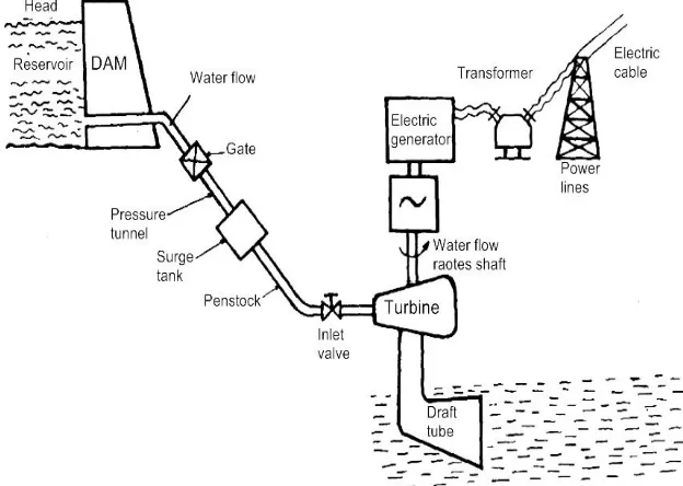
The principle of hydro power is extraction of potential energy from nature by utilising the head available and discharge and converts into mechanical energy and then to electrical energy. In case of hydraulic turbines, the water moves from higher elevation to lower elevation and during its movement, the available potential energy is converted either fully into kinetic energy or partially into kinetic and partially into pressure energy at the inlet of turbine depending upon the type of turbine.
Hydraulic turbines are not only used to convert hydraulic energy into electrical energy but also in pumped storage plant which is most efficient for the storage of electrical energy in the large scale. In these plants, pump as turbine (PAT) is used.
[image:2.612.147.459.483.705.2]A. Main Components of Reaction Turbine
1) Spiral Casing: The spiral casing is closed passage where cross section area decreases gradually around the circumference. This leads to uniform distribution of water along the circumference of the runner. The main function of spiral casing is to maintain uniform velocity along complete and to impart some whirl to flowing water.
2) Stay Vanes: The main function of stay vanes shown in fig. 1.3 is to direct the quantity of water supplied to the guide vanes and so as to align the flow of water from the spiral casing to the guide vanes which reduces the impact loss on the guide vane. It also transmits the load of turbine to foundation
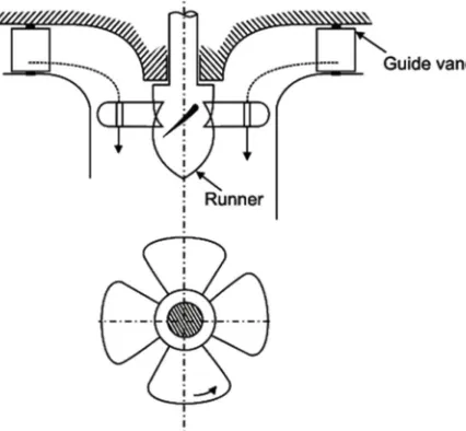
3) Guide Vanes: The main function of guide vanes is to regulate or control the quantity of water supplied to the runner and to direct water to the runner at an angle with respect of the turbine design so as to reduce the shock loss on runner.
[image:3.612.199.412.226.423.2]4) Runner: The runner which can be termed as heart of turbine consists of series of curved vanes uniformly set around the circumference within annular space between two plates. The flow in the runner may be radial, axial or combination of both.
Fig. 2 Typical view of Kaplan turbine runner
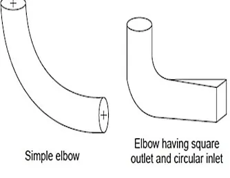
5) Draft Tube: The draft tube recovers part of K.E. coming out of runner into useful pressure energy and thus improves the performance of turbine. The provision of draft tube at runner outlet decrease the pressure and lead to problem of cavitation which can be minimized by proper setting of runner above tail race.
Fig. 3 Shapes of draft tubes
II. LITERATURE REVIEW
Summary of some research papers are mentioned herewith the emergence of the reaction turbine draft tube comes in to consideration in the first half of the nineteenth century. The first draft tube was used by the Herschel and Jonval between 1837-1841. In the slow speed reaction turbines the draft tube affects very much on their power characteristics. But due to the transmission problems there was a need of small hydro power stations, to fulfil that requirements small turbines were designed. First experimental facilities were established in 1879.In 1903 a special hydraulic turbine laboratory was built in Zurich. Initially the draft tube had a cylindrical shape and were used only to connect the runner to trail race. These turbines were constant cross-sectional area helped only in the use of the static vacuum. i.e. were useful only for positive height of runner above the trail race.
In case of very low head and high speed turbines the kinetic energy at runner exit is very high and the height of the runner above the trail race is very small so cylindrical draft tube do not affecting much the power characteristics of the hydraulic turbines. K. Pfarr was first to suggest the use of straight conical tube with inlet and outlet areas of different cross-sections. At the expense of this vacuum at the runner exit increases with the reduction of kinetic energy and converted in to the useful pressure energy. The Initial hydrodynamic investigations on straight draft tube were carried out between 1903 and 1907. F. Frankal and A.Y. Milovich in their calculations proceeded from the assumptions that the wall of the draft tube should be drawn as stream line of potential flow of an ideal fluid. But they had not found any useful practical stream line of potential flow of an ideal fluid. But they had not found any useful practical result because they had not considered the complex fluid flow phenomenon at draft tube inlet as like swirling flow etc.
assumptions were all unsuccessful in obtaining higher power coefficients. Due to large divergence between actual and assumed characteristics were the causes of failure.
In 1924 Professor A.Y.Milovich, postulated, on theoretical basis, a new shape of curved draft tubewith a continuous increase of cross-sectional area along the length with a smooth turning in the form of elbow. It was found that the power coefficient of this draft tube is also not high so it do not find practical application. Further investigations were conducted by C.A.Chaplygin and P.A. Walter on the curved draft tube and there elements. F.F. Gubin, E.F. Gurbich and S.V. Chernyshevskii in 1939, and thereafter Prof. V.S. Kvyatkovskii and still later D. I. Kumin observed that draft tube of the diffuser type operated better when a certain amount ofcirculation exist at the entrance of the tube. This phenomenon reduces the boundary layer at the wall of draft tube and the flow is uniform over the tube section, it increases the overall efficiency of turbine. Professor Kaplan, in connection with the development of high speed variables angle runner blade turbines with small head, designs a curved draft tube of small height with an elbow much smaller than in current use. This draft tube has very high power coefficient. The major part of velocity head is recovered in the cone before the elbow.
Skotak Ales et al. [2007] investigated the flow for the originally installed draft tube during the process of up gradation of low head Kaplan turbine. The performance of separate draft tube has been classified by analysis of CFD simulations in order to clarify the best inflow conditions. The detailed unsteady CFD simulations were carried out in order to recognize draft tube separation phenomenon more precisely.
Prasad Vishnu et al. [2010] carried the numerical flow simulation for 3D viscous turbulent flow in elbow draft tube by varying its parameters like length and height at different mass flow rate using Ansys CFX code.The draft tube efficiencies and losses are computed from pressure and velocity distributions and presented graphically to study the effect of geometrical parameters on draft tube performance. The prediction of geometrical parameters from numerical simulation for the best performance is matching to the geometry of draft tube used in most of the hydro power stations.
Vu T. C. et. al. [2010] has presented a validated numerical simulation approach to evaluate global draft tube performance. This approach, based on steady-state flow simulations using the k-ε turbulence model and a moderately refined mesh, offers a highly
effective methodology that can reliably be used by designers to compare relative global draft tube performance of nearby design operating points.This study demonstrates the importance of the choice of turbulent inlet boundary conditions even close to the best efficiency operating condition.
Shukla Manoj Kumar et al. [2011] has done 3-Dimensional (3-D) real flow analysis for experimentally tested turbine and the characteristics of prototype turbine were predicted in actual operating regimes. The operating condition considered as actual prototype turbine and analyzed flow structure inside the machine and showed the improvement in the design of casing tip portion by visualization of result in CFX-post and validated the result with experimental results.
Khare Ruchi et al. [2012] discussed the 3D viscous steady flow simulation for the complete flow passage of Francis turbine by using commercial Computational Fluid Dynamics (CFD) code for three runner solidities at different rotational speeds.The draft tube performance parameters in non-dimensional form are computed from simulation results and the effects of runner solidity and operating speed on draft tube performance are discussed. The simulation results are also compared with the experimental results for validation and are found to be reasonable accurate.
Tanase Nicoleta Octavia et al. [2012] presented numerical simulation of the flow in the draft tube of the Kaplan turbine, using the Open FOAM -1.5-dev. The test case of a draft tube of a Kaplan Turbine of the Turbine-99 was simulated. The results are compatibles with the state of art presented in literature. The general representation of the flow is well catch by the flow simulation. However to use the CFD for quantitative analyses in term of efficiency or local behaviour, more accurate inlet condition and turbulence models are needed.
Bajaj Rahul et. al. [2014] finds that the numerical simulation of elbow draft tube with dividing pier has its maximum efficiency at L= 10 * D1 length of the draft tube. The comparative study of the pressure variations and velocity contours at the inlet section of draft tube and just after the elbow section shows that location of dividing pier effects the velocity distribution significantly. Efficiency of draft tube is affected due to whirl component.
III. NEED, OBJECTIVE AND SCOPE OF WORK
A. Need of Work
1) The draft tube plays an important role on overall performance of reaction turbine.
elbow draft tube with rectangular outlet.
3) The shape and area of draft tube at outlet as well as along its length may improve the efficiency of turbine.
B. Objective and scope of the work
1) The objective of present work is to study the effect of geometry of draft tubes used in Kaplan turbine on both draft tube efficiency as well as turbine performance.
2) To compute the local and global parameter of Kaplan Turbine by changing the geometry of draft tube and validate the CFD results.
3) Redesigning the existing draft tube by changing the shapes of draft tube, such as elliptical, square, circular and rectangular.
4) The draft tube with and without splitters are also analyzed for its performance.
5) Analysis of CFD results and their comparison.
IV. CONCLUSION
Redesigning the existing draft tube can be done by changing the shapes of draft tube, such as elliptical, square, circular and rectangular. Performance & efficiency of Kaplan turbine can be improved. We can apply this analysis to other turbines also so that the performance & efficiency can be improved. The shape and area of draft tube at outlet as well as along its length may improve the efficiency of turbine. CFD can be used for analysing draft tube geometry.
REFERENCES
[1] M.F. Gubin, "Draft Tubes of Hydro-Electric Stations", (1973), Amarind Publishing Company Private Ltd, New Delhi.
[2] Ernesto Casartelli, Thomas Staubli, (2006), "Impact of Rotor Side Space Flow on Draft Tube Performance" Hydrovision Hci Publications.
[3] J.G.I. Hellstrom, B.D. Marjavaara, T.S. Lundstro, (2007), “Parallel CFD Simulations of an Original and Redesigned Hydraulic Turbine Draft Tube”, Advances
In Engineering Software Vol. 38, pp.338-344.
[4] Christopher, B. Cook, Marshall C. Richmond, John A. Serkowski, (2007),"Observations of Velocity Conditions Near a Hydroelectric Turbine Draft Tube Exit
Using ADCP Measurements", Flow Measurement and Instrumentation,
[5] Vol. 18 , pp.148–155.
[6] Motycak, A Skotak, J Obrovsky, (2010),"Analysis of the Kaplan Turbine DraftTube Effect" IAHR Symposium on Hydraulic Machinery and Systems IOP Publishing.
[7] Sylvain Tridon, Stephanebarre, Gabriel Dan Ciocan, Laurent Tomas, (2010), "Experimental Analysis of the Swirling Flow in a Francis Turbine Draft Tube:
Focus on Radial Velocity Component Determination", European Journal of Mechanics B/Fluids, Vol. 29, pp.321-335.
[8] Vishnu Prasad, Ruchi Khare, Abhas Chincholikar, (2010), "Hydraulic Performance of Elbow Draft Tube for Different Geometric Configurations Using CFD",
IIT Roorkee, India
[9] A Ruprecht, M Heitele, T. Helmrich, (2010) “Numerical Simulation of a Complete Francis T
[10] urbine including unsteady rotor/stator interactions”, Institute for Fluid Mechanics and Hydraulic Machinery University of Stuttgart, Germany.Ruchi Khare, Vishnu Prasad, Sushil Kumar Mittal, (2012), "Effect of Runner Solidity on Performance of Elbow Draft Tube", Energy Procedia, Vol. 14 pp. 2054- 2059.
[11] Yongzhongzeng, Xiaobing Liu, Huiyan Wang,(2012), "Prediction and Experimental Verification of Vortex Flow in Draft Tube of Turbine Based on CFD",
International Conference on Advances in Computational Modeling and Simulation, PROCEDIA Engineering Vol.31, pp.196- 205.