©IJRASET: All Rights are Reserved
214
Finite Element Analysis of Front Axle of Farm
Tractor Using CAE Tools
Ravikant1
1Department of Mechanical Engineering, Amity University Haryana
Abstract: Front Axleis attached to the front side of the Tractor and is used in the process of steering the machine towards right or left and is one of the major and very important components. Designing of the components is very important aspect, as this part experiences the worst load condition of the whole tractor. Our objective of the work is to carry out FEA analysis of front axle. The 3D model of front axle was generated in CATIA and then imported in ANSYS workbench. In this work static analysis of the front axle of a tractor has been taken as a case study. The Von Mises stress, strain and total deformation obtained for the same loading condition and compared with the existing results.
Keywords- Front axle, FEA, CATIA, Ansys.
I. INTRODUCTION
Agricultural Tractor is one of the main example,for off-road vehicles category. Off-road condition includes uneven agricultural field surfaces and bumpy village roads on which the tractor has to operate. These ground irregularities leads to unexpected loads coming on the Tractor components. The primary purpose of tractor is to have mobile machinery to generate pull also known as drawbar pull. This drawbar pull is utilized for various operations like ploughing, haulage, cultivation etc. Besides this basic operation Tractor is used for applications like loader. Front Axle of Tractor is one of the major and very important component and needs very good design as this part experiences the worst load condition of the whole tractor.
The main objective of this research is to analyze the front axle of farm tractor and to reduce the total deflection while maintaining the stress in body under the permissible yield stress.
Leon et al. [2000] used experimental and numerical methods, for the stress analysis of a frontal truck axle beam. The results obtained by finite element method were verified experimentally using photo stress.
Mahanty et al. [2001] performed an experimental and numerical analysis of a tractor’s front axle. Based on finite element analysis results redesign was carried out for the front axle for weight optimization and easy manufacturability. Five different models were proposed based on ease of manufacture and weight reduction. The results obtained by finite element method were analyzed by thirteen different certification test load conditions. Maly and Bazzaz (2003) used experimental and numerical methods, for design change from casting to welding for an axle casing. Ali Jafari et al [2006] have done Stress Analysis and optimization of Front Axle of JD 955 Combine Harvester under Static Loading. Dr. Sajan Pawar et al performed the Non Linear Analysis of Farm Tractor Front axle using ABAQUS CAE. The Non Linear behavior of axle was simulated in ABAQUS CAE.
ALI JAFARI1, et.al JD 955 combines manufactured by Iran Combine Manufacturing Company was modified. Resulting from the applied modifications, total weight and the loads applied on front axle of modified combine were increased. Stress analysis of front axle of JD 955 combine under static loading conditions resulted from the applied modifications was performed by using finite element method. The commercial finite element package ANSYS version 9.0 was used for the solution of the problem. Numerical results showed that the calculated value of factor of safety is very low and the front axle of JD 955 combine isn’t strong enough to be installed on the modified combine.
II. MATERIAL
The material taken for the front axle is structural steel . This material have following properties – E = 210 GPa`, υ = 0.3
ρ = 7850 Kg/m3, σu = 350 MPa
III.MODELLINGANDMESHINGOFFRONTAXLE
Figure 1-CAD model of Front axle
[image:3.612.190.437.279.439.2]The meshing of the front axle was done in ANSYS workbench using tetrahedral element. The no. of nodes and elements generated were 44626 and 22282 respectively.
Figure.2- Meshed model of Front axle
IV.BOUNDARYCONDITIONS
After making the geometric model, it is subjected to the boundary conditions and loading. Two cylindrical supports are given at the ends as shown in figure – 3
Figure 3- Applied Constraints
[image:3.612.185.427.503.677.2]©IJRASET: All Rights are Reserved
216
V. RESULTS
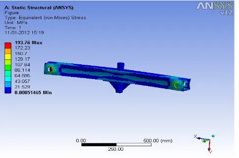
[image:4.612.193.436.129.290.2]The FEA result of the front axle have been analyzed and compared with the available experimental results for validation. The Fig. 4 shows the von-mises contour of the front axle for a load of 35000 N. The maximum stress is found to be (188.71 MPA) near the cylindrical support. The value of maximum stress is well below the yield stress (235 MPA) for the Structural steel.
[image:4.612.180.435.344.481.2]Figure 4- Equivalent (Von-Mises) Stress of front axle.
[image:4.612.191.432.504.649.2]Fig.5 shows the deflection in each element of front axle front axle. The maximum deflection in the axle under the influence of load 35000 N is 0.269 mm which is well below the available results for deflection in the specified component.
Figure 5- Total deformation of front axle
Figure 6- Equivalent (Von-Mises) elastic strain of Front axle
VI.CONCLUSION
Technology (IJRASET)
A. The max. Von- mises stress observed in the front axle was 193.76 MPa for the load of 35,000 N.
B. The max. Deformation obtained in front axle was 0.269 mm which is negligible and harmless.
C. The max. Equivalent Von – mises elastic strain obtained in front axle was 0.000968. The results obtained are well in agreement with the similar available experimental results. The model presented here is well safe and under permissible limit of stresses.
REFERENCES
[1] Leon, N., P.O. Martinez and P. Adaya, 2000. “Reducing the Weight of a Frontal Axle Beam Using Experimental Test Procedures to Fine Tune FEA”, 2nd Worldwide MSC Automotive Conference, Dearborn,Michigan
[2] Mahanty, K.D., V. Manohar, B.S. Khomane and S. Nayak, 2001, “Analysis and Weight Reduction of a Tractor’s Front Axle.” Tata Consultancy Services, India, Swarup Udgata, International Auto Limited, India
[3] Shigley, J.E. and C.R. Mischke, 1989. Mechanical Engineering Design, 5th Edition. McGraw-Hill Book Company [4] Maly, J. and E. Bazzaz, 2003. “Design Change from Casting to Welding for an Axle Casing”.
[5] Dr Sajan Pawar, Dr Prakash Kamath and Mr Rajesh Upadhyay,Non Linear Analysis of Farm Tractor Front axle using ABAQUS CAE, Mahindra & Mahindra ltd Tractor division
[6] Ali jafari, Majid Khanali, Hossein Mobli and Ali Rajabipour, “Stress Analysis of Front Axle of JD 955 Combine Harvester under Static Loading”, Department of Agricultural Machinery, University of Tehran, Karaj, Iran*FEB,2006.