2019 International Conference on Artificial Intelligence, Control and Automation Engineering (AICAE 2019) ISBN: 978-1-60595-643-5
Research on Two-speed AMT Shift Control Strategy for Pure Electric
Commercial Vehicles
Ning MA
1,*, Kai REN
1, Ye-xuan WANG
1, Ben-jiang HOU
1, Shao-xin CHEN
1,
Yi ZHOU
1, Jian-yi JI
2and Yi-chun JI
21China University of Petroleum, No. 66, Changjiang Road, Huangdao District, Qingdao, China
2Qingte Group Co., Ltd., No. 777, East Zhengyang Road, Chengyang District, Qingdao, China
*Corresponding author
Keywords: Pure electric commercial vehicle, AMT, Shift schedule, Dynamic performance, Economic performance.
Abstract. At present, in the rapid development of the automobile industry, the field of pure electric vehicles is full of vitality. Among them, motorization of commercial vehicles is undoubtedly one of the important means to solve environmental degradation and energy shortage. Based on a pure electric commercial vehicle, this paper matches and calculates the motor parameters and AMT transmission ratio according to the basic parameters and performance indexes of the vehicle. The research design and simulation of the shift control strategy are also completed. The simulation results show that the automatic shift control strategy is designed to meet the dynamic and economic requirements of the vehicle and it has certain practical reference value.
Introduction
In recent years, with the rapid development of China's economy and the improvement of people's living standards, vehicles have gradually entered the homes of ordinary people, and their holdings have increased year by year. However, environmental degradation and energy shortages have begun to constrain the development of the traditional automobile industry. Therefore, people are eager to find a way to replace traditional fuel vehicles, and the development of electric vehicles is undoubtedly one of the main solutions [1].
At present, most of the pure electric vehicles use a fixed speed ratio one-speed reducer. This transmission system has a simple structure and low cost, but puts high requirements on the performance of the drive motor. At the same time of high instantaneous torque, the drive motor is necessary to provide a higher operating speed in the constant power zone to meet the dynamic design requirements of the vehicle [2]. In addition, in order to ensure the vehicle speed range, more motor working points will fall in the low speed-high load area and high speed-low load area, which greatly reduces the motor efficiency. Therefore, the development of the transmission system structure of electric vehicles tends to be two-speed or multiple-speed, and relevant research has been done at home and abroad [3,4,5,6].
Based on the above problems, this paper designs a two-speed AMT according to the design parameters of a pure electric commercial vehicle and designs a comprehensive shift schedule that considers both dynamic and economic performance. Finally, the automatic shift control strategy is studied.
Vehicle Parameters
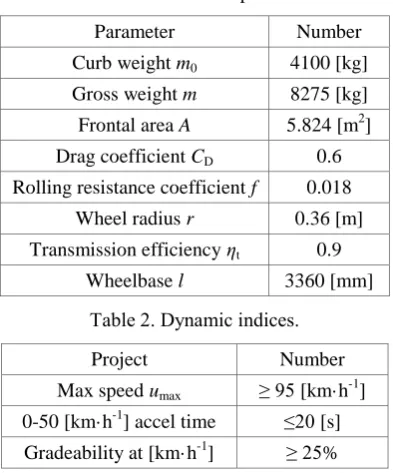
Table 1. Vehicle basic parameters.
Parameter Number
Curb weight m0 4100 [kg]
Gross weight m 8275 [kg]
Frontal area A 5.824 [m2]
Drag coefficient CD 0.6
Rolling resistance coefficient f 0.018
Wheel radius r 0.36 [m] Transmission efficiency ηt 0.9
Wheelbase l 3360 [mm]
Table 2. Dynamic indices.
Project Number
Max speed umax ≥ 95 [km·h-1]
0-50 [km·h-1] accel time ≤20 [s]
Gradeability at [km·h-1] ≥ 25%
Transmission System Parameter Matching
The transmission system of the pure electric commercial vehicle studied in the paper adopts the drive motor-drive axle combined structure, and the motor output shaft is directly connected with the reduction gear and the differential, there is no the shifting clutch. This arrangement has the characteristics of compact structure, simple installation and high transmission efficiency, but has high requirements on the performance of the motor and the control precision of the controller [7].
Drive Motor Parameters Matching. At present, there are four main types of drive motors used in pure electric vehicles: DC motors, AC asynchronous motor, permanent magnet synchronous motor and switched reluctance motor [8]. The pure electric commercial vehicle designed and studied in this paper uses permanent magnet synchronous motor as the driving motor, which has the advantages of good speed regulation performance, high efficiency, low loss and low cost.
Drive motor parameter matching mainly considers the rated power and peak power of the motor: the rated power must guarantee the power required when the vehicle operates at the maximum speed and the peak power must meet the acceleration performance and climbing performance of the electric vehicle.
The rated power of the motor should be determined by considering the three conditions of maximum speed, maximum grade and acceleration performance:
𝑃v =1 t(
𝑚0g𝑓
3600𝑢max+
𝐶D𝐴
76140𝑢max
3 )
𝑃i = 1
t( 𝑚0g𝑓
3600𝑢α +
𝐶DA
76140𝑢α3+
𝑚0g𝛼max
3600 𝑢α)
𝑃a =1 t(
𝑚g𝑓𝑢a
3600 +
𝐶D𝐴
76140𝑢a
3 + 𝛿𝑚
3600(
𝑑𝑢
𝑑𝑡)max𝑢a) (1)
where g is the acceleration of gravity, 𝑢max is the maximum speed of the vehicle, 𝑢α is the speed at which the vehicle travels at constant speed on the maximum grade, 𝛼max is the maximum grade,
(𝑑𝑢𝑑𝑡)
max is the maximum acceleration of the vehicle, 𝛿 is the correction coefficient of rotating
mass.
𝑃𝑒 ≥ max {𝑃𝑣, 𝑃𝜆𝛼, 𝑃𝜆𝑎} (2)
where λ is the overload factor of the drive motor.
The peak power 𝑃max of the drive motor can be obtained as:
𝑃𝑚𝑎𝑥 = 𝜆 ∙ 𝑃𝑒 . (3) Based on the above considerations, this paper uses the TZ365XSB02 permanent magnet synchronous motor of Jing-Jin Electric Technologies (Beijing). The basic parameters are shown in Table 3.
Table 3. TZ365XSB02 parameter.
Parameter Number Parameter Number
Peak power 125[kW] Rated power 85[kW]
Peak speed 6000[r·min-1] Rated speed 2520[r·min-1]
Peak torque 600[N·m] Rated torque 320[N·m]
AMT Parameters Matching. The driving conditions of pure electric vehicles are complex and varied. In order to improve the performance of the vehicle, the shifting mechanism needs to match the appropriate gear ratio. At present, the AMT transmission solutions applied to pure electric vehicles mainly include: one-speed AMT, two-speed AMT and three-speed AMT. This paper decided to adopt two-speed AMT that is small in size, light in weight, relatively simple in structure, and can fully exert the performance of the driving motor, so that the electric vehicle has good comprehensive performance and is widely used in electric vehicles [9].
1) Matching of maximum transmission ratio
The maximum transmission ratio 𝑖max is the product of the final reduction drive ratio 𝑖0 and the transmission first gear ratio 𝑖1, which is determined by the gradeability of the vehicle. It can be obtained from formula (4):
𝑖max≥ (𝑚g𝑓𝑐𝑜𝑠𝛼max+𝑚g𝑠𝑖𝑛𝛼max+
𝐶D𝐴𝑢α2 21.15 )𝑟
𝑇max𝜂t (4)
where 𝑇max is the peak torque of the drive motor.
In addition, from the perspective of adhesion, the vehicle should be prevented from slipping during driving:
𝐹tmax =𝑇max𝑖𝑟max𝜂t≤ 𝜙𝐹z = 𝜙𝑚g𝑏𝑙 (5)
where 𝐹z is the normal reaction force of the ground to the wheel, 𝜙 is the road adhesion coefficient, 𝑙 is the wheelbase, 𝑏 is the distance from the center of mass to the rear axle.
The condition that the maximum gear ratio needs to be satisfied can be obtained by formula (5):
𝑖max≤ 𝑇𝜙𝑚g𝑟𝑏
max𝜂t𝑙 (6)
2) Selection of minimum transmission ratio
The minimum transmission ratio 𝑖min of the transmission system is determined by the maximum
speed of the vehicle.
𝑖min ≤ 0.377𝑛max𝑟
𝑢max (7)
where 𝑛max is the peak speed of the drive motor.
Design of AMT Shift Control Strategy
Whether the automobile shifts on the best shifting point is decided by the shift schedule, which also determines the degree of performance of the vehicle. The overall shift schedule generally takes the dynamic shift schedule and economic shift schedule into consideration.
Optimal Dynamic Shift Schedule. The optimal dynamic shift schedule means that the AMT system performs the shifting operation at the shift point where the vehicle has the maximum power, which maximizes the output power of the motor and improving the dynamic performance of the vehicle [9].
According to the driving motor parameters, the curve of the relationship between the accelerator pedal opening angle α, the motor speed n and the motor torque T is fitted as shown in Figure 1.
Figure 1. Fitted curve of α-n-T. Figure 2. Simulation module of the dynamic shift.
Based on the transmission system structure designed in this paper, the dynamic shift simulation module is built in MATLAB/Simulink simulation software, as shown in Figure 2.
Through the above simulation module, the relationship between vehicle speed and acceleration under the different accelerator pedal opening angle and the different gears is obtained, as shown in Figure 3.
Figure 3. Fitted curve of dynamic shift schedule.
It can be seen from the simulation results that under the different accelerator pedal opening angle, the intersection points of the acceleration curves of the first and second gears are roughly concentrated in a certain area. In this area, a straight line perpendicular to the speed axis is taken as the downshift or upshift curve of the dynamic shift. In addition, in order to avoid the occurrence of cyclic shift the speed between the downshift and upshift curve should be 2~8 km·h-1 [9].
Optimal Economic Shift Schedule. The optimal economic shift schedule means that the AMT performs the shifting operation at the most efficient shift point, which maximizes the use of the motor and battery efficiency area and improves the economy of the vehicle.
Based on MATLAB/Simulink, the economic shift schedule simulation module is established, and obtain the relationship between vehicle speed and motor efficiency under the different accelerator pedal opening angle and the different gears, as shown in Figure 5.
[image:5.595.78.497.113.238.2]
Figure 4. MAP of the drive motor. Figure 5. Fitted curve of economic shift schedule.
The method for formulating the economic shift schedule is as follows: the motor efficiency curve of the first gear and the second gear has an intersection point when an accelerator pedal opening degree and the speed corresponding to the intersection point is taken as the shift point. And when no intersection points this paper selects the speed corresponding to the end point of the efficiency curve of low gear as the shift point. The selected shift point is fitted into a curve, and then we can get an economic shift curve.
[image:5.595.197.401.425.548.2]Overall Shift Schedule. Through the comparison of the dynamic and economic shift schedule, it can be found that the dynamic shift is mainly concentrated in the high load area, while the economic shift is mainly concentrated in the low load area. When the vehicle is running at a low load, the motor power required is small and the economic shift is mainly considered. And when running at high load the motor power required is larger, so its dynamic is mainly concentrated. Considering various aspects comprehensively the overall shift schedule curve is obtained, as shown in Figure 6.
Figure 6. Overall shift schedule.
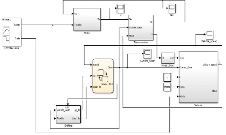
Automatic Shift Control Strategy. This paper also studies the automatic shift control strategy of the vehicle. Based on MATLAB/Simulink the vehicle simulation model is established, as shown in Figure 7. The design of the automatic shift control strategy is based on the EXAMPLE in the software.
[image:5.595.183.413.627.764.2]The automatic shift control module receives signals of the current gear, the real-time vehicle speed (ut), and the real-time accelerator pedal opening angle. When the current gear is in the first
gear, the real-time vehicle speed is compared with the speed of the upshift curve (uus) under the
real-time accelerator pedal opening angle, if ut ≤ uus it doesn't shift and if ut > uus it sends a shift
signal to switch to the second gear. When the current gear is in the second gear, the real-time vehicle speed is compared with the speed of the downshift curve (uds) under the real-time
[image:6.595.90.509.365.482.2]accelerator pedal opening angle, if ut ≥ uds it doesn't shift and if ut < uds it switches to the first gear.
Figure 8. Simulated input signal.
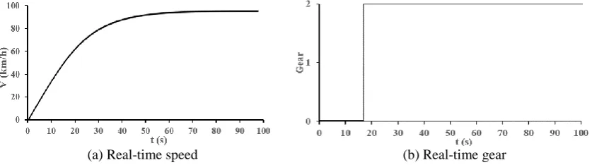
This paper adopts the start accelerated simulation test to verify whether the automatic shift control strategy is feasible. On the well road, the vehicle starts to accelerate from zero speed. The input acceleration pedal and brake pedal signals are shown in Figure 8. The simulation results of the real-time speed and gear of the vehicle are shown in Figure 9.
(a) Real-time speed (b) Real-time gear
Figure 9. Simulation results.
It can be seen from the simulation results: the vehicle speed gradually increased. When the vehicle just started to accelerate, the speed increased rapidly. Soon the speed reached 98.5 km·h-1, after which the speed remained about the same and was basically consistent with the designed maximum vehicle speed. Also, when the vehicle reached a certain speed, the gear was switched from the first gear to the second gear.
Conclusion
(1) This paper has taken a pure electric commercial vehicle as the prototype, and matched the parameters of the drive motor and the AMT, which theoretically met the performance requirements of the vehicle.
(2) This paper has studied the shift schedule, designed the overall shift schedule and formulated the automatic shift control strategy. After that the initial acceleration simulation test was carried out and the simulation results met the performance requirements of the vehicle, which had a certain practical reference value.
Acknowledgement
References
[1] Cui Weijia. Research on Permanent Magnet Motor and Drive Control in Electric Vehicle Application [D]. Nanjing University of Aeronautics and Astronautics, 2015.
[2] Chen Shujiang, Qin Datong, Hu Minghui, et al. Pure Electric Vehicle AMT Comprehensive Shift Strategy Considering Dynamics and Economic Performances [J]. China Mechanical Engineering, 2013, 24(19):2687-2692.
[3] Wang Jianwen. The Research and Simulation Analysis of the Shift Process of a Two Speed AMT for Electric Vehicle [D]. Chongqing University, 2016.
[4] Wang R, Zhang L, Yu C, et al. A New Powertrain of Two Speeds for Pure Electric Vehicle[C]// 2013:51-53.
[5] Ren Q, Crolla D A, Morris A. Effect of transmission design on Electric Vehicle (EV) performance[C]// 2009 IEEE Vehicle Power and Propulsion Conference. IEEE, 2009.
[6] Pinto S D, Camocardi P, Sorniotti A, et al. A Four-Wheel-Drive Fully Electric Vehicle Layout with Two-Speed Transmissions[C]// Vehicle Power and Propulsion Conference. IEEE, 2015:1-6.
[7] Shao Yuxia. The Pure Electric Vehicle Drive System and Its Layout [J]. Auto Maintenance & Repair, 2013(03):82-86.
[8] Shang Yunmiao. Electromechanics [M]. Beijing; Mechanical Industry Press, 2011.
[9] Zhou Deming. Design and Study of the Control Strategies of Electric Vehicle's Integrated Motor-gearbox System [D]. HeFei University of Technology, 2014.