2019 International Conference on Computer Science, Communications and Multimedia Engineering (CSCME 2019) ISBN: 978-1-60595-650-3
Intelligent Lock Design Based on BLE
Tao LI, Xiu-li YU, Yu-jian TANG and He CHEN
Beijing Smart-Chip Microelectronics Technology Co., Ltd., Beijing 100192
Keywords: BLE, Electric power security, Intelligent lock control system, Passive.
Abstract. This design is of intelligent electric power security lock and its key based on the new generation SoC TLSR8253, which supports Bluetooth LE 5.0 technical standard. The system is mainly composed of intelligent electronic key, intelligent passive lock, Bluetooth handset and management center. Intelligent passive locks can be opened with powering by electronic keys, and can retrospectively manage keys and users, bind personnel identity, control the power of opening and closing, improving site safety and enhancing the manageability of assets.
Introduction
At present, the safety protection of indoor equipment such as power stations, transformer substations, distribution stations, the ring cabinets, box transformers, branch boxes, underground cable covers and other outdoor equipment in the distribution network of China's power industry, most of them still use mechanical locks (padlocks, handle locks, cabinet locks). Its reliability and safety are not high. Safety incidents such as illegal invasion, theft and disoperation of power equipment and facilities occur from time to time, which brings serious hidden dangers to the safe
operation of power[1-3].
In addition, it is inconvenient to open the meter box by carrying a large number of keys when collecting, maintaining, changing and viewing meters. The current lock control cannot track and record the switch information of the ammeter box. When the ammeter box is opened abnormally by illegal persons, it can't alarm in time and is very vulnerable to electricity theft.
In order to meet the intelligent requirements of power safety operation and management in the new situation, a smart lock control system for electric power safety based on BLE 5.0 technology is designed. Through the advanced technology of Internet of things, Internet plus information integration, the dynamic security control of all kinds of power grid equipment and facilities can be realized, and the current matching / changing power grid can be well solved. The problems of safe operation and management are helpful to the development of power grid.
System Design
The intelligent lock control system for power security designed in this paper mainly includes four parts: cloud server, Bluetooth handset, intelligent key and intelligent passive lock. The system structure chart is shown in Figure 1. This paper will focus on the embedded software and hardware design of keys and locks, and Bluetooth handset is a common handset of national network system with Bluetooth communication in the market. Server development is not the focus of this journal and will not be discussed in detail.
The smart key communicates with the handset first, then it downloads the password replacement information of the smart lock acquired from the cloud server in the handset and updates its own password. After inserting the key, it supplies power to the intelligent lock, and communicates with the intelligent lock to complete the lock-related information such as unlocking, unlocking record reading, password replacement, etc., and communicates with the handset to upload the unlocking information of the record.
Cloud Server
and improve the safety of the site, and strengthen the manageability of assets and the responsibility of users. It is suitable for equipment safety management and personnel field management in the working process of inspection, maintenance and construction in various industries.
Bluetooth Handset
Bluetooth handset can communicate with server or key through Bluetooth. It can update key privilege information, etc.
Intelligent Key
Intelligent keys are divided into two kinds, one is common keys, which are used by unlocking personnel on the spot. It has the functions of identifying locker-unlocking personnel, recording information and unlocking, and the other is management keys, which have the function of changing the key of intelligent locks.
Management Center
Intelligent Key
Bluetooth handset
Bluetooth Terminal Equipment
Padlock Cabinet door lock
[image:2.595.178.417.253.372.2]Intelligent Lock
Figure 1. Structural Diagram of Intelligent Lock Control System.
Intelligent Passive Lock
It is use for two-way security verification of the key, and confirming the legal identity of the key, and unlocking, and recording the unlocking information.
Hardware Circuit Design
The following is the implementation of some specific circuits of intelligent key and intelligent passive lock core.
Intelligent Key
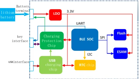
The hardware circuit of intelligent key is composed of BLE5.0 SoC control circuit, lithium battery and its charging circuit, security encryption module, etc. It mainly receives the authentication and control information of the handset through Bluetooth and drives the intelligent passive electronic lock through contact. At the same time, the state information and switch record of the intelligent passive electronic lock are transmitted to the handset through Bluetooth.
BLE SOC
Flash
RTC chip lithium
battery LDO
ESAM Charging
Protection Chip
USB charging
chip
SPI
I2C 3.3V
Battery terminal
key interface
USBinterface
UART
[image:2.595.179.420.619.755.2]BLE5.0 SoC Control Circuit
TLSR8253 is a new generation of BLE SoC which supports BLE5.0 and Mesh networking. It can provide high integration and ultra-low power applications. It integrates 32 bit MCUs, BLE RF transceivers, 48KB SRAM, 512KB internal Flash, 14-bit ADC with PGA, 6-way PWM and rich GPIO interfaces on a single chip, including supporting for almost all peripherals needed for BLE
applications development[5].
Lithium Battery and Its Charging Circuit
In the smart key, the main power source comes from lithium batteries, which can be charged through USB interface. USB charging circuit uses AP5054C as the main chip, while VA7062MER chip is used to build charging protection circuit.
Secure Encryption Module
The security encryption module uses ESAM (Embedded Secure Access Module) chip to complete data encryption and decryption, two-way identity authentication, access control, temporary key export functions. It communicates with BLE SoC via SPI.
B Intelligent Lock Core
The hardware circuit of the intelligent lock core realizes the single-line serial communication with the intelligent key and the electronic driving function of the mechanical locking structure. The hardware structure diagram is shown in Figure 3.
MCU LDO
ESAM
SPI key interface
UART
DC motor
3.3V
[image:3.595.185.420.368.503.2]3.3V
Figure 3. Hardware System Diagram of Intelligent Lock Core.
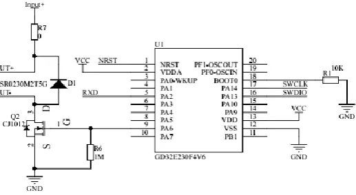
Main Control Circuit
The MCU GD32E230F4V6 based on Cortex M0 core is used as the main control chip of the lock core. Its LGA20 small size package can break through the restriction of volume approaching in the lock core. The drive of DC motor is realized by simple power amplification through N-channel MOSFET, as shown in Fig. 4.
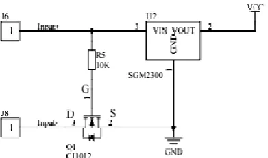
[image:3.595.172.431.622.764.2]Figure 5. Intelligent Lock Core Power Supply Circuit Diagram.
Power Supply Circuit
The power supply of the lock core is built with the LDO chip SGM2300 encapsulated in SOT23, which further reduces the size of the circuit board.
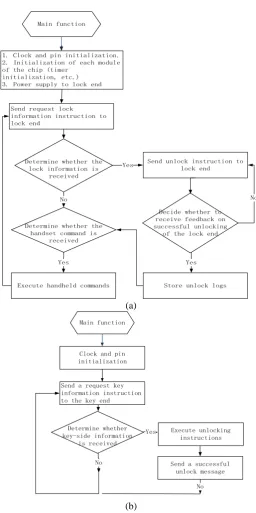
Embedded Software Design
The design of embedded software mainly includes the software design of TLSR8253 and GD32E230F4V6. The software flow chart is shown in Figure 6.
A BLE Module Software Design
The Tailing BLE software architecture consists of the APP application layer and the BLE Stack protocol stack, where the stack_config.h file is used to configure some configuration parameters in the BLE protocol stack. BLE protocol can be divided into two parts: Bluetooth Application and Bluetooth Core, and Bluetooth Core includes BLE Controller and BLE Host. Controller is responsible for defining the specifications of partial hardware such as RF, Baseband, and abstracting the logical links for communication on this basis; Host is responsible for more friendly encapsulation on the basis of logical links, which can shield the details of Bluetooth technology and make Bluetooth Application more convenient to use
Send request lock information instruction to lock end
Determine whether the lock information is
received
Send unlock instruction to lock end
Decide whether to receive feedback on successful unlocking
of the lock end
Store unlock logs Yes
Main function
Determine whether the handset command is
received No
1. Clock and pin initialization. 2. Initialization of each module of the chip (timer
initialization, etc.) 3. Power supply to lock end
Execute handheld commands Yes
No
Yes
(a)
Send a request key information instruction to the key end
Determine whether key-side information
is received
Execute unlocking instructions
Send a successful unlock message Yes
Main function
No Clock and pin initialization
No
(b)
Figure 6. (a) Main Program Flow Chart of Key-side BLE SoC; (b) Main Program Flow Chart of Lock-side MCU.
References
[1] Zhang Wenjia, Chen Qikang et al. Design and implementation of Android for BLE intelligent lock [J]. Industrial control computer, 2018 (03): 83-85.
[2] Huang Jianxiong, Wang Hua, et al. Research on the application of intelligent locks in power industry [J]. Modern Information Technology, 2018, (10): 88-90.
[3] Huang Haijing, Jiang Wei. Discussion on Substation Key Management Application [J]. Electrical Technology, 2015, (09): 69-75.
[4] Wang Yihuai, Liu Xiaosheng, et al. Passive Intelligent Power Lock Based on Internet+Communication World, 2017. (01): 241.
[image:5.595.166.423.60.575.2]