2018 3rd International Conference on Information Technology and Industrial Automation (ICITIA 2018) ISBN: 978-1-60595-607-7
A Control Method of Inverter to Implement the
Three-Phase Current Imbalance Compensation
Xia Zhang
ABSTRACT
Based on three-phase four-leg inverter structure, a control method of inverter is studied to implement the three-phase current imbalance compensation. The control method of three-phase four-leg inverter is studied for micro grid power quality problems caused by three-phase current imbalance, using positive and negative sequence synchronous rotation coordinate conversion and band-stop filter, the positive sequence , negative sequence and zero-sequence current are separated to be controlled, and phase inverter output current follows the command, three-phase current imbalance compensation is realized effectively. Based on theoretical analysis, a simulation model and experimental platform are build, and the feasibility and correctness of the system control methods is verified by simulation and experiments.1
INTRODUCTION
The entire micro grid is equivalent to a load for the main grid, which organizes a variety of distributed power sources, loads and energy storage effectively[1-3].When a variety of distributed power supply, load, energy storage devices are connected to the micro grid, it is inevitable to generate three-phase unbalanced current. The harm of three-phase unbalanced current generated in the micro grid is multifaceted, which brings about power quality problems and influences the control of distributed power supply, load, energy storage devices and other devices connected to the micro grid. When the micro grid is connected to the grid, interference will also occur to the grid, such as increasing line loss, copper loss and so on [4].Solving the problem of unbalanced three-phase current is of great significance for improving the power
1
quality of micro-grid. Primary energy usually requires power electronic devices for power conversion and integration into the power grid, so power electronic devices play a key role in power transmission[5].
Three-phase four-arm inverter adds a bridge arm to the topology of three-phase three-arm inverter, which has unbalanced current output capacity[6].Based on the three-phase four-bridge arm inverter, the control method is studied in this paper. Through reasonable control, the system can follow the current instruction, output the three-phase unbalanced current, realize the three-phase unbalanced current compensation function, and the control method is verified by simulation and experiment.
SYSTEM CONTROL PRINCIPLE
System Extension Structure
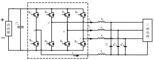
In this paper, the control algorithm of three-phase four-bridge arm inverter is studied based on the three-phase four-bridge arm inverter. The system studied is a three-phase inverter system, and the system extension structure is shown in figure 1.
As shown in figure 1, the system obtains the required AC output from DC input through DC/AC. LC filtering is adopted in the system, and the inverter adopts the three-phase four-bridge inverter structure, which has the three-phase unbalanced current output capacity.
Inverter Control Method
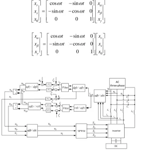
[image:2.612.218.377.598.660.2]In order to simplify the control algorithm, the static coordinate system is transformed to the rotating coordinate system. The three-phase unbalanced current can be decomposed into positive order, negative order and zero order components. Based on the positive order synchronous rotation of dq coordinate system, a negative order synchronous rotation of rs coordinate system in the opposite direction is added. The sinusoidal time-varying ac in the three-phase static coordinate system is simultaneously transformed into the spatial rotation vector in the positive order synchronous rotation dq coordinate system and the negative order synchronous rotation rs coordinate system through the positive order and negative order rotation transformation.
Figure 1. Diagram of system.
a
b c S1
S4
S2
S5
S3
S6
n S7
S8
三相四桥臂逆变器
直 流 源
The coordinate transformation formula and its inverse transformation formula of the positive order synchronous rotation dq0 coordinate system from the alpha gamma coordinate system to the positive order synchronous rotation dq0 coordinate system are shown in equation (1) and (2), where is the rotational angular frequency of the synthetic vector.
0
cos sin 0
sin cos 0
0 0 1
d
q
x t t x
x t t x
x x (1) 0
cos -sin 0
sin cos 0
0 0 1
d
q
x t t x
x t t x
x x (2)
The coordinate transformation formula of the coordinate system of synchronous rotation of alpha gamma coordinate system to negative order rs0 coordinate system is shown in equation (3) and (4),where is the angular frequency of rotation of the synthetic vector.
0
cos sin 0
sin cos 0
0 0 1
r
s
x t t x
x t t x
x x
(3)
0
cos sin 0
sin cos 0
0 0 1
r
s
x t t x
x t t x
x x
[image:3.612.157.480.362.668.2] (4)
Through the rotation transformation, the sinusoidal quantity of the fundamental wave in the static coordinate system is transformed into the direct flow, which is conducive to the design of the control algorithm.
In the dq coordinate system of positive order synchronous rotation, the positive order component is the dc component, and the negative order component is the sine of frequency 2ohm, which is the rotational angular frequency of the synthetic vector. In rs coordinate system, the positive order component is a sinusoidal quantity with frequency 2 ohm, and the negative order component is a direct flow. Through the band resistance filter, filter 2 ohm component, can get the direct flow, for control.
The system control block diagram is shown in figure 2.After PI adjustment and coordinate transformation, the Ua, Ub, Uc component in the static coordinate system can be obtained, where the duty cycle of the fourth bridge arm is 0.5. Through SPWM modulation, the modulation signal of each bridge arm can be obtained to realize the three-phase four-arm inverter control.
SIMULATION AND EXPERIMENTAL RECEARCH
Simulation Research
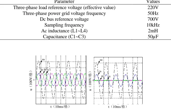
[image:4.612.129.466.435.652.2]The inverter system model is built on the Matlab simulation platform for simulation research. The parameter setting is shown in table 1 for simulation research.
TABLE I. PARAMETERS FOR THE SYSTEM.
Parameter Values
Three-phase load reference voltage (effective value) 220V Three-phase power grid voltage frequency 50Hz
Dc bus reference voltage 700V
Sampling frequency Ac inductance (L1~L4)
Capacitance (C1~C3)
10kHz 2mH 50µF
(a)Balanced Current-Output(b)Unbalanced current output
Figure 3. Simulation result of the system.
ia ib ic
u
(
100
V
/
格
)
0
t(10ms/格) ua
ia
ib ic
u
(
100
V
/
格
)
0
It can be seen that the system current instruction is balanced to A fixed time, and the three-phase ac current of A, B and C is balanced to output, following the given 100A;When the system current instruction is unbalanced, the three-phase ac current of A, B and C is unbalanced and output, following the given 100A, 0A and 0A, it can be seen that the system has the three-phase unbalanced current compensation function.
Experimental Research
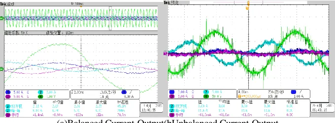
In order to verify the control strategy, a three-phase grid-connected inverter system experimental platform was built. The experimental system filter parameters and simulation system parameters were the same, and the voltage and current conditions were correspondingly reduced.
The three-phase balance current instruction and three-phase unbalance current instruction are given respectively to carry out experimental tests on the system. The experimental operation results are shown in figure 4.Among them, figure 4 (a) as the dc bus voltage of 80 v, three-phase ac voltage peak adjustment to 40 v, a given size of 3 a balance of three phase current amplitude, phase with grid voltage experiment result, figure 4 (b) for the dc bus voltage of 200 v, three-phase ac voltage peak adjustment to 90 v, unbalanced three-phase current amplitude size are given respectively, 5A, 0, 0 a phase with grid voltage experiment results.
Analyzing the experimental operation results, the system current instruction is balanced to a fixed time, and the three-phase ac current of A, B and C is balanced to output, following the given 3A;when the system current instruction is unbalanced, A, B and C three-phase ac current output is unbalanced. Follow the given 5A, 0A and 0A, and it can be seen that the system has the three-phase unbalanced current compensation function.
[image:5.612.127.467.478.603.2](a)Balanced Current-Output(bUnbalanced Current-Output
CONCLUSIONS
The power quality problem caused by unbalanced current in the micro-grid not only affects the operation of distributed power supply, load, energy storage devices under its control, but also causes disturbance to the grid when it is connected to the grid. Based on three-phase four-bridge inverter, a control method of inverter which can realize unbalanced current compensation is studied. Through theoretical analysis, the simulation model and experimental platform are built, and the simulation and experimental system test are carried out to verify the feasibility and correctness of the control method, which has important application value for improving the power quality of micro grid.
REFERENCES
1. Xiaozhi Gao. Research on Microgrid Control and Power Quality Improvement[D]. Tianjin University.2011.
2. Shuangjian Peng. Study on Microgrid Operation Control and Power Quality Control. Hunan University.2011.
3. Yunwei Li, Vilathgamuwa D M, Loh P C. A Grid-Interfacing Power Quality Compensator for Three-Phase Three-Wire Microgrid Application [J]. IEEE Transactions on Power Electronics, 2006,21(4): 1021-1031.
4. Yueming Gao. Hazards and Countermeasures of Unbalanced Currents in Low-Voltage Power Grid[J].Journal of Shengli Oil Field Staff University. 2009(03):5-15.
5. Yanghua Liu, Zhengqiu Wu, Youqing Tu, et al. A Survey on Distributed Generation and its Net Working Technology[J]. Power System Technology,2008,32(15):71-76(in Chinese).